2019 2nd International Conference on Informatics, Control and Automation (ICA 2019) ISBN: 978-1-60595-637-4
Using UVM Testbench to Generate the Analog Stimuli
Xu HUANG, Xin HE, Zheng-rong HE
and Xiao-zong HUANG
Sichuan Institute of Solid State Circuits, Chongqing, P.R. China
Keywords: Analog stimuli, Universal Verification Methodology, Constrained Random Verification.
Abstract. In an environment for verifying digital designs, constrained random verification is employed to create lots of scenarios that help to uncover deep-rooted bugs in the design. Analog blocks such as Analog-to-Digital Converters (ADC), voltage regulators need a similar kind of verification environment to ensure the quality of design. Effects of noise on supply, abrupt changes in voltage sources have to be observed to evaluate the performance of the design. Self-checking and highly automated testbenches generating analog stimuli are required for this purpose. In this paper we present an approach to drive analog stimuli to the Design-Under-Test (DUT) from a SystemVerilog testbench based on Universal Verification Methodology (UVM). Verilog-AMS models were developed for the analog components in the DUT.
Introduction
Design of high-performance complex SoCs in low power envelopes is causing both analog and digital designs to increase in complexity. This intensifies the need for more robust verification of these designs. Many methods are adopted in the industry for verifying digital designs. Constrained random verification helps in creating lots of scenarios that help to uncover bugs in the early stages of digital design development. Analog blocks such as ADCs and voltage regulators need a similar kind of verification environment to ensure the quality of design. Conventional circuit simulations fail to address this need as the driven stimulus is static in nature. Effects of noise on supply and abrupt changes in voltage sources have to be observed to evaluate the performance of the design. Self-checking and highly automated testbenches generating analog stimuli are required for this purpose.
Design Challenge
In a DUT with both analog and digital interface, it is relatively easy to verify the digital interface with randomization introduced from a SystemVerilog testbench. However, driving continuous signals on the analog interface from a SystemVerilog testbench has traditionally been a challenge. These analog ports are of electrical discipline, which can take in voltage or current levels. For example, to drive a voltage signal which sweeps from 0 to 1.8 V with some random slew rate, we cannot do this through a simple SystemVerilog testbench due to the following reasons:
• SystemVerilog does not support electrical discipline.
• Driving real values through a SystemVerilog interface is another limitation.
• Though there are methods to drive analog signals in which the values are static, there are no known methods where these values can be randomized and dynamically changed during the simulation.
Figure 1. PWL waveform of varying supply voltage.
Figure 2. Code snippet for PWL waveform in Figure 1.
Analog signals can be driven in the above mentioned manner to the DUT, but these values are static. The voltage levels can neither be changed dynamically nor controlled through the testcase, which restricts the scope for randomization. This has been a challenge to increase the scope of verification. Everytime we need to change these voltage levels, we will have to update the code snippet in Fig. 2, compile, and rerun.
Proposed Solution
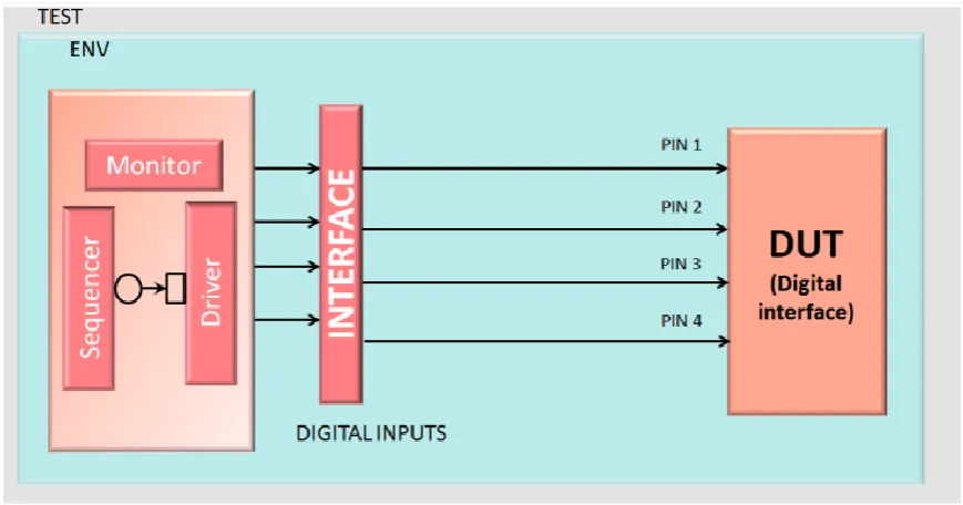
Verification on a digital interface can be performed by conventional UVM-based SystemVerilog testbench. Fig.3 shows such an environment, where the digital inputs of the DUT are constrained and
randomized from Universal Verification Component (UVC)[1]. To have a similar concept for analog
[image:2.595.80.515.506.734.2]verification, where the stimuli can be either changed dynamically or even pick random values, we propose a UVM-based SystemVerilog testbench with VerilogAMS models. Any DUT with ports of electrical disciple can be verified using this concept.
Figure 3. Verification ENV for digital interface.
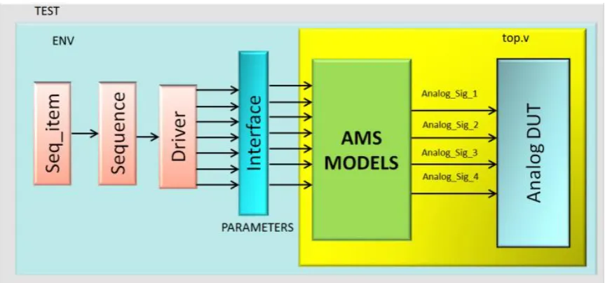
to the top level .v file are driven through a SystemVerilog interface. These inputs are nothing but parameters that control the generation of required analog stimuli. These parameters can be randomized or changed dynamically through testcases in a similar manner as done in constrained random verification for a digital interface[2].
Figure 4. Implementation of Verification ENV.
The flow is explained to generate a dynamically varying reference voltage of a voltage regulator, this is nothing but a PWL waveform which is dynamic in nature. Parameters that control the shape of analog signals can be randomized or dynamically changed from the test. The voltage levels that the reference voltage can take is constrained in the sequence item. Code snippet for a sequence item is shown in Fig.5. These parameters can also be controlled from the sequence in case we want to configure the values for a particular case. Fig.5 shows the case where rise and fall times are configured in the sequence. These voltage controlling parameters along with rise and fall times are then passed to the driver through these sequences. An example for this is shown in the code snippet in Fig.5. Parameters from the sequence item drive these random values to the interface through the driver. Interface signals corresponding to these parameters are of type integer instead of type real which is a limitation to drive real values to the voltage signals.
Figure 5. Code snippet for sequence item, sequence and driver.
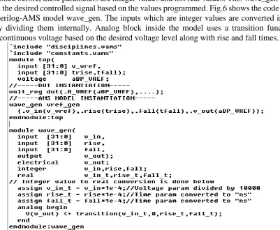
[image:3.595.133.460.507.733.2]signals to the DUT. The Verilog-AMS models take these parameter signals as the inputs and generate required pin wiggles on the DUT electrical ports based on the values programmed[3]. Fig.6 shows the top.v module where DUT and Verilog-AMS modules are instantiated. Wave_gen in the top.v is the Verilog-AMS model that takes, v_vref, trise, tfall parameters to generate the desired output voltage. As mentioned before, these parameters are integer values and not real values. This wave_gen module generates the desired controlled signal based on the values programmed. Fig.6 shows the code snippet for the Verilog-AMS model wave_gen. The inputs which are integer values are converted into real values by dividing them internally. Analog block inside the model uses a transition function to generate continuous voltage based on the desired voltage level along with rise and fall times.
Figure 6. Code snippet for top.v and Verilog-AMS model wave_gen.
In this way, we can generate continuous analog voltage/current signals of desired shape by having appropriate Verilog-AMS models. The scope of verification can be widened by incorporating constrained random parameters that can be dynamically controlled through a UVM testbench.
Results
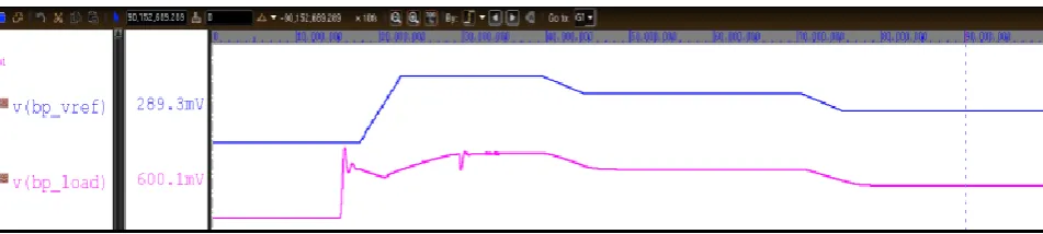
Figure 7. Waveform of PWL voltage stimulus along with output load voltage.
Conclusions
We have described an approach to dynamically control analog stimuli through a self-checking UVM testbench. A library of Verilog-AMS models can be developed with various parameters that helps to control the shape of analog stimuli required by the testbench. A generic wave generator model is developed, which can be used for generating PWL and stair-case voltage signals. This model takes in voltage levels, rise times, and fall times as its input parameters to generate appropriate signals. A triangular wave generator model is also developed for triangular waves, with control over maximum and minimum voltages, and switching frequency. The testbench randomizes these parameters to generate different triangular waves across simulations.
This approach helps in robust verification of analog blocks, when compared to the traditional verification of these analog blocks by circuit simulations. These models can also be reused for verification of SPICE netlists as well. The quality of the design will be higher due to the constrained random verification of these blocks with current and voltage checkers implemented by probing analog ports.
References
[1] UVM Cookbook. [Online]. Available: www.verificationacademy.com. Retrieved July, 2014.
[2] Verilog-AMS LRM, Accellera, Version 2.3.1, June 2009.