International Journal of Emerging Technology and Advanced Engineering
Website: www.ijetae.com (ISSN 2250-2459,ISO 9001:2008 Certified Journal, Volume 3, Issue 2, February 2013)
175
Channel Estimation and Optimization for Pilot Design in
MIMO OFDM Systems
K.Vidhya
1,
K. R. Shankarkumar
21
AP/ECE, 2Professor/ECE, Sri Ramakrishna Engineering College, Coimbatore-22
Abstract-- In this paper, pilot carriers are designed using particle swarm optimization method. It is compared with random and orthogonal placement of pilot that are used for LS channel estimation in MIMO OFDM systems. Channel estimation is done with the help of bit error rate and mean square error corresponding values of signal to noise ratio. In this paper , the position of pilots are also investigated. Mat lab software is used to design a pilot. According to the simulation results, PSO is an effective solution for designing pilot carriers.
Keywords–LS, MIMO- OFDM, orthogonal, pilot, PSO,
I. INTRODUCTION
OFDM is a multi carrier modulation technique which has the capability to mitigate the effect of inter symbol interference at the receiver side. MIMO techniques are used with OFDM (MIMO –OFDM ) to enhance the system performance. MIMO OFDM systems are capable of increasing the channel capacity even under severe channel conditions. This system provide two dimensional space frequency coding (SFC) in space and frequency using individual subcarriers of an OFDM symbol or three dimensional coding called space time frequency coding (STFC) to achieve larger diversity and coding gain.
OFDM can also be used in multi user cooperative communication system by assigning subcarrier to different users for overall transmit power reduction. Most of the MIMO techniques have been developed ݣwith the assumption of flat fading channel. For broad band frequency selective wireless channel , the combination of MIMO OFDM was proposed to mitigate the effect of inter symbol interference and inter carrier interference[1]. In MIMO techniques, channel state information is usually required at transmitter and receiver side. Thus OFDM is also used in MIMO OFDM system to estimate CSI.
II. MIMO OFDM SYSTEM MODEL
In OFDM , divide band into N narrow subcarrier transmit at symbol rate 1/T = W/N for each sub channels. Parallel transmission rate W/N each, total rate = N X W/N.
Multi carrier avoids inter symbol interference when N is large that means symbol duration is long. IFFT is used to implement N parallel orthogonal subcarrier then insert the cyclic prefix . It avoids interference between OFDM symbols and makes the convolution of IFFT values and channel impulse response circular also makes the received signal after FFT as a multiplication of channel response and data for each subcarrier[2]
III. CHANNEL ESTIMATION
Channel is a most general sense can describe everything from the source to the sink of the radio signal including the physical medium. Channel model is a mathematical representation of the transfer characteristics of the physical medium . Channel models are formulated by observing the characteristics of the received signal[3]. It explains the received signal behavior is used to model the channel. Channel estimation is the process of characterizing the effect of physical medium on the input sequence. The aim of the channel estimation is to minimize mean square error and utilize as little computational resources as possible allowing easier implementation. It allows the receiver to approximate the effect of the channel on the signal. Channel estimation is essential for removing inter symbol interference , noise rejection techniques etc
Channel estimation is one of the important portions in communication systems . An exact channel estimation algorithm should encompass both the time and frequency domain characteristics for the OFDM systems . The performance of OFDM system can be enhanced by allowing for coherent demodulation when a precise channel estimation algorithm is employed[4] . In OFDM transmission system, several channel estimation techniques have been proposed under the assumption of a slow fading channel, in which the channel transfer function remain stable within one OFDM data block.
IV. CHANNEL ESTIMATION TECHNIQUES
International Journal of Emerging Technology and Advanced Engineering
Website: www.ijetae.com (ISSN 2250-2459,ISO 9001:2008 Certified Journal, Volume 3, Issue 2, February 2013)
176
In training sequence method, sequence known to the receiver are embedded into the frames and sent over the channel. It is easily applied to any communication systems. It is most popular method used today and not too computational intense. It’s draw back is wasteful of the information bandwidth. In Blind Method, no training sequence is required. It uses certain underlying mathematical properties of the data being sent . This method is excellent for applications where bandwidth is scarce. It has drawback of being extremely computational intensive. It is hard to implement on real time systems[5].Channel state information is vital for data detection and also for channel equalization. It can be obtained in different ways that is training symbols that are a prioriknown at the receiver, whereas the other is blind, relies only on the established symbols, and it acquires CSI by exploiting statistical information and/or transmitted symbol properties like finite alphabet, constant modulus. Though, compared with training, blind channel estimation usually requires a long data record[6]. Therefore, it is limited to slowly time-varying channels and entails high complexity. Due to this reason it restrict attention to training-based channel estimation is done.
Typical procedures for identifying the channel based on training utilize multiple OFDM symbols that consist completely of pilot symbols. For single-input single-output (SISO) systems, this approach can be found [7] whereas for multiple-input multiple-output (MIMO) systems, it can be found in [8]. In these systems, the CSI is estimated prior to any transmission of data. When the CSI changes considerably, a retraining sequence is transmitted. In a fast time-varying environment systems must continuously retrain to re-estimate the CSI. Among retraining, these systems experience an increased BER due to their outdated channel estimates.
V. PILOT
Pilots are inserted for channel estimation and coherent detection at receiver side. Pilot symbol aided channel estimation must be used to track the variation of the channel. LS method was chosen for initial channel estimation in pilots at receiver. Pilot symbols facilitate channel estimation , they reduce the transmit energy for data symbols per OFDM symbol under a fixed total transmit power constraint[9]. The effect of pilot symbol aided channel estimation in MIMO OFDM systems with three different types of pilot patterns. Random pilot , Orthogonal pilot and Optimized pilot.
The optimal placement and power of pilot signals for maximizing capacity and minimize the bit error rate. We analyze the channel estimation error, according to three different pilot patterns to see how the channel estimation error affects the BER of MIMO OFDM systems. The interference from the antenna and sub carriers cause a large amount of interference we consider three pilot transmit schemes that eliminate this in order to allow better performance[10].
VI. LEAST SQUARE ESTIMATION
To eliminate channel state information least square is derived as follows[11]. The output sequence can be written as
Yq = Ahq + Wq (1)
Channel impulse response hq can be estimated by least
square algorithm ĥq = AtY
q = hq +AtWq (2)
From equation MSE of LS channel estimation can be obtained as follows
MSE = 1 E{ ‖ ĥq - hq‖ } (3)
─
LN
tVII. PARTICLE SWARM OPTIMIZATION
The PSO is robust stochastic optimization technique based on the movement and intelligence of swarms. It is very efficient optimization algorithm by searching an entire high dimensional problem space. The advantages of the PSO are the simple implementation and it’s quickly convergence ability[12]. In PSO, simple software agent called as particles that represent as potential solutions are placed in the search space of function and evaluate the objective function at their current location. Each particle searches for better position in the search space by changing velocity according to rules.
International Journal of Emerging Technology and Advanced Engineering
Website: www.ijetae.com (ISSN 2250-2459,ISO 9001:2008 Certified Journal, Volume 3, Issue 2, February 2013)
177
A large inertia weight w facilitates a global search, while a small inertia weights facilitates a local search. Suitable selection of the inertia weights provides a balance between global and local exploration abilities and thus requires less iteration on the average to find the optimum[14]. In this paper, inertia weight is linearly decreased from w max to w min according tow = w max _ wmax -wmin
_________________ X iteration (4) Iteration max
At first , the particles that represent pilot positions are initialized at random values between 0 and 255 for the system which has 256 subcarriers. All the possible combinations of particle positions are tested using fitness function that is Rmax / P . If the fitness of particle’s current
position is better than previous best position , the velocity and position of particle are updated. These processes are repeated till the stopping criteria are carried out that are 500 iterations for the systems which has 256 subcarriers. After the fixed number of iterations , best global particles are chosen as pilot tone positions.
VIII. SIMULATION RESULTS
The simulation parameters for the MIMO OFDM system with two transmit antenna and two receive antenna are given in Table I
TABLE I
MIMO OFDM SIMULATION PARAMETERS
Parameter Value
No of subcarrier 256
No of Pilot 32
No of data subcarrier 224
Pilot interval 8
Channel length 16
No of TX and RX 2 X 2
Modulation Type QAM
No of iteration 500
In simulations, we evaluate the performance of various pilot tones:
1. Random placed pilot tones 2. Equi spaced orthogonal pilot tones
[image:3.612.335.547.143.356.2]3. Optimized location of pilot tones using PSO
Figure 1. SNR vs BER for various pilot tones with 256 subcarrier
[image:3.612.326.563.475.693.2]Figure 1 shows that SNR versus BER of different pilot tones for 256 subcarriers . The bit error rate for optimized pilot is minimum compared to orthogonal and random pilot. It can be seen that in case of placing pilot tones randomly, the system has poor performance comparing to other methods because of channel estimation errors.
TABLE II
BER VALUES FOR VARIOUS PILOT TONES
Eb/N0 ORTHOGONAL
PILOT
RANDOM PILOT
OPTIMIZED PILOT
0 0.2877 0.3178 0.0545
2 02433 0.2864 0.0417
4 0.1995 0.2582 0.0285
6 0.1580 0.2282 0.0218
8 0.1204 0.2020 0.0143
10 0.0863 0.1743 0.0103
12 0.0603 0.1588 0.0071
14 0.0400 0.1448 0.0041
16 0.0268 0.1383 0.0033
18 0.0172 0.1295 0.0019
20 0.0116 0.1250 0.0014
22 0.0069 0.1243 0.0015
24 0.0045 0.1211 0.0012
26 0.0027 0.1212 9.0351e-4
28 0.0018 0.1181 8.329e-4
30 0.0010 0.1181 6.0704e-4
0 5 10 15 20 25 30
10-4 10-3 10-2 10-1 100
SNR in dB
B
it
E
rr
o
r
R
a
te
BER
International Journal of Emerging Technology and Advanced Engineering
Website: www.ijetae.com (ISSN 2250-2459,ISO 9001:2008 Certified Journal, Volume 3, Issue 2, February 2013)
[image:4.612.337.543.144.396.2]178
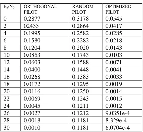
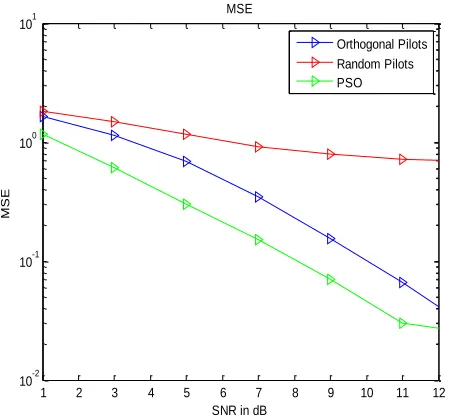
Table II shows that bit error rate values for various SNR. The PSO pilot provides better performance compared to instead of placing them randomly and orthogonally.Figure2. SNR vs MSE for various pilot tones for 256 sub carriers
In figure 2, SNR versus MSE of different pilot tones for 256 subcarriers are indicated . The mean square error for optimized pilot is minimum compared to orthogonal and random pilot. It can be seen that in case of placing pilot tones randomly, the system has poor performance comparing to other methods because of channel estimation errors.
TABLE III
MSE VALUES FOR VARIOUS PILOT TONES
Eb/N0 ORTHOGONAL
PILOT
RANDOM PILOT
OPTIMIZED PILOT
1 1.6398 1.8274 1.1533
3 1.1370 1.4849 0.6040
5 0.6863 1.1617 0.3036
7 0.3438 0.9134 0.1506
9 0.1529 0.7950 0.0708
11 0.0662 0.7188 0.0299
13 0.0259 0.6962 0.0248
15 0.0101 0.6789 0.0176
[image:4.612.60.285.186.394.2]Table III shows that mean square error values for various SNR. The optimized pilot provides better performance compared to instead of placing them randomly and orthogonally.
Figure 3. position of various pilot tones
[image:4.612.333.555.461.702.2]This figure 3 shows for random, orthogonal, and optimized placement of pilot tone.
TABLE IV
PILOT POSITION OF VARIOUS METHODS
PILOT ORTHOGONAL
PILOT
RANDOM PILOT
OPTIMIZED PILOT
1 1 0 0
2 0 0 1
3 0 0 0
4 0 0 0
5 0 0 0
6 0 0 0
7 0 1 0
8 0 0 0
9 1 0 0
10 0 0 0
11 0 0 1
12 0 0 0
13 0 1 0
14 0 1 0
15 0 0 0
16 0 0 0
17 1 0 0
18 0 0 0
1 2 3 4 5 6 7 8 9 10 11 12
10-2 10-1 100 101
SNR in dB
M
S
E
MSE
Orthogonal Pilots Random Pilots PSO
50 100 150 200 250
0 0.1 0.2 0.3 0.4 0.5 0.6 0.7 0.8 0.9 1
Pilot position
International Journal of Emerging Technology and Advanced Engineering
Website: www.ijetae.com (ISSN 2250-2459,ISO 9001:2008 Certified Journal, Volume 3, Issue 2, February 2013)
[image:5.612.334.562.145.409.2]179
This Table IV shows pilot position for random, orthogonal and optimized placement of 256 subcarriers.Figure 4. channel impulse response
[image:5.612.70.274.169.415.2]This figure 4 shows the channel impulse response of the channel
TABLE V
CHANNEL MATRIX VALUES
H11 H12 H21 H22
0.0764-0.0 0.0754-0.0 0.0586-0.0 0.0699-0.0 0.116+0.0 0.0770-0.0 0.0622+0.0 0.0516-0.0 0.0717+0.0 0.0904+0.0 0.0583-0.0 0.0123-0.0 0.0777+0.0 0.0890-0.0 0.0667-0.0 0.0554+0.0 0.1179-0.0 0.0572-0.0 0.0812-0.0 0464-0.0 0.0903-0.0 0.0709-0.0 0.0807-0.0 0.0550-0.0 0.0847+0.0 0.0984-0.0 0.0514+0.0 0.0370+0.0 0.0901-0.0 0.0735-0.0 0.0578-0.0 0.0531+0.0
Table V shows that values of channel matrix for 2x2 MIMO OFDM system
Figure 5. Noise
This figure 5 shows that noise added in the channel for different sample.
TABLE VI MAGNITUDE OF NOISE
S.NO NOISE MAGNITUDE
1 -1.9016e-4
2 0.00304+0.0
3 0.0040+0.0
4 0.0138+0.0
5 0.0005+0.0
6 0.0027+0.0
7 -0.0079-0.0
8 -0.0187-0.0
9 -0.0146-0.0
10 -0.0183-0.0
This Table VI shows that magnitude of noise
0 2 4 6 8 10 12 14 16 18
0 0.02 0.04 0.06 0.08 0.1 0.12 0.14
Channel Impulse response
0 50 100 150 200 250 300 350
-0.04 -0.03 -0.02 -0.01 0 0.01 0.02 0.03 0.04
NOISE
Samples -->
M
a
g
n
it
u
d
e
[image:5.612.338.549.461.611.2]
International Journal of Emerging Technology and Advanced Engineering
Website: www.ijetae.com (ISSN 2250-2459,ISO 9001:2008 Certified Journal, Volume 3, Issue 2, February 2013)
180
IX. CONCLUSION
In this paper, we have proposed particle swarm optimization to optimize the placement of pilot tones which are used in LS channel estimation algorithm in MIMO OFDM system. From the simulation results , we can see that optimized pilot tones derived by particle swarm optimization outperforms the orthogonal and random pilot tones significantly in terms of BER and MSE. We can place optimize pilot tone compared to random and orthogonal. According to the simulation results, PSO is an effective solution for designing pilot carriers.
REFERENCE
[1 ] M. K. Ozdemir and H. Arslan, “Channel estimation for wireless
OFDM systems,” IEEE Communications Sur- veys & Tutorials, vol. 9, no. 2, pp. 18–48, 2007.
[2 ] L. Tong, B. M. Sadler, and M. Dong, “Pilot-assisted wireless
transmissions: general model, design criteria, and signal processing,” IEEE Sig. Proc. Mag., vol. 21, no. 6, pp. 12–25, 2004.
[3 ] R. Negi and J. Cioffi, “Pilot tone selection for channel estimation in
a mobile OFDM system,” IEEE Trans.on Consumer Elect., vol. 44, no. 3, pp. 1122–1128, 1998.
[4 ] S. Adireddy, L. Tong, and H. Viswanathan, “Opti- mal
placement of training for frequency-selective block- fading channels,” IEEE Trans. on Info. Tech., vol. 48, no. 8, pp. 2338– 23853, Aug. 2002
[5 ] R. J. Baxley, J. E. Kleider, and G. T. Zhou, “Pilot design for OFDM
with null edge subcarriers,” IEEE Trans on Wireless Com., vol. 8, pp. 396 –405, Jan. 2009.
[6 ] S. Ohno, E. Manasseh, and M. Nakamoto, “Pilot symbol design for
channel estimation in OFDM with null sub- carriers,” Asia Pacific Signal and Information Processing Association (APSIPA), pp. 696– 699, Oct. 2009.
[7 ] M. Shin, H. Lee, and C. Lee, “Enhanced channel- estimation
technique for MIMO-OFDM systems,” IEEE trans. on Veh. Tech., vol. 53, no. 1, pp. 61 –265, Jan. 2004.
[8 ] E. G. Larsson and J. Li, “Preamble design for multiple- antenna
OFDM-based WLANs with null subcarriers,” IEEE Sig. Proc. Let., vol. 8, no. 11, pp. 325 –327, Nov. 2001.
[9 ] D. Hu, L. Yang, Y. Shi, and L. He, “Optimal pilot se- quence design
for channel estimation in MIMO OFDM systems,” IEEE Com. Let., vol. 10, no. 1, pp. 1–3, Jan. 2006.
[10 ]Q. Huang, M. Ghogho, and S. Freear, “Pilot design for MIMO
OFDM systems with virtual carriers,” IEEE Trans. on Sig. Proc., vol. 57, no. 5, pp. 2024-2029, May 2009
[11 ]Z. Li, Y. Cai, and Y. Xu, “Optimal training signals de- sign for
MIMO OFDM systems with guard subcarriers,” Proc. VTC 2006-Spring Vehicular Technology Confer- ence IEEE 63rd, vol. 3, pp. 1541–1544, 2006.
[12 ]M. Sandell, J. Coon, “Near-optimal training sequences for
MIMO-OFDM systems with nulled subcarriers,” IEEE GLOBECOM ’05, vol. 4, pp. 2243 –2249, Dec.2005
[13 ]IEEE Standard for Local and Metropolitan Area Net- works Part 16:
Air Interface for Fixed Broadband Wire- less Access Systems, IEEE Std., 2004.
[14 ]M. Morelli and U. Mengali, “A comparison of pilot- aided channel