COGGING TORQUE REDUCTION OF 6S-4P
SPOKE-TYPE IPMSM USING A NEW
COMBINATION OF ROTOR DESIGN
FATIHAH SHAFIQAH BINTI BAHRIM
COGGING TORQUE REDUCTION OF 6S-4P SPOKE-TYPE IPMSM USING A NEW COMBINATION OF ROTOR DESIGN
FATIHAH SHAFIQAH BINTI BAHRIM
A thesis submitted in
fulfillment of the requirement for the award of the Degree of Master of Electrical Engineering
Faculty of Electrical and Electronic Engineering Universiti Tun Hussein Onn Malaysia
This dissertation is dedicated to my beloved mother ROHAYAH BINTI ADNAN and my father BAHRIM BIN SALIM. My brothers, and sisters, who have always
v
ACKNOWLEDGEMENT
ABSTRACT
vii
ABSTRAK
TABLE OF CONTENTS
TABLE OF CONTENTS viii
LIST OF SYMBOLS AND ABBREVIATIONS xi
LIST OF TABLES xiv
LIST OF FIGURES xv
LIST OF PUBLICATIONS xix
LIST OF AWARDS xxi
CHAPTER 1 INTRODUCTION 1
1.1 Research Background 1
1.2 Problem Statement 2
1.3 Objectives 3
1.4 Scope 3
1.5 Thesis Outline 4
CHAPTER 2 LITERATURE REVIEW 6
2.1 Introduction 6
2.2 Overview of Permanent Magnet Synchronous Motor
(PMSM) 6
2.3 Review of Cogging Torque 8
2.4 Cogging Reduction Method 12
2.5.1 Skewing the Slots/Poles/Magnet 13
2.5.2 Slot Opening Variation 16
2.5.3 Stator tooth Pairing 18
2.5.4 Rotor teeth/pole-pairing and Axial Pole
ix 2.5.5 Stator/rotor pole displacement design 21 2.5.6 Slot and pole number combination 23
2.5.7 Dummy Slot/Notching 24
2.5.8 Rotor pole-chamfering 27
2.5.9 Magnet shifting 29
2.5.10 Magnet Pole Arc 30
2.5.11 Magnet Optimization 32
2.5.12 Flux barrier 33
2.5.13 Combination Techniques. 34
2.5 Summary 36
CHAPTER 3 RESEARCH METHODOLOGY 37
3.1 Introduction 37
3.2 Design and Investigation using Conventional Skewing, Notching, Radial Pole Pairing and Axial Pole Pairing
Methods 38
3.2.1. Design Configuration of Conventional Cogging Torque Reduction Methods 40 3.2.2. Investigation using JMAG-Designer 43 3.2.3. Performance Analysis of 6S-4P Spoke-type
IPMSM 45
3.3 Design and Investigation of New Combination Method for Cogging Torque Reduction 50 3.3.1 Design Configuration of Proposed Combination
Method for Cogging Torque Reduction 50 3.4 Design Analysis to Improve the Best Cogging Torque
Reduction Method 52
3.5 Summary 52
CHAPTER 4 RESULTS AND DISCUSSION 53
4.1 Introduction 53
4.2 Design Results and Analysis Using Conventional Skewing, Notching, Radial Pole Pairing and Axial
4.2.1. Open Circuit Analysis Performance on The
Basis of 3-D FEA 55
4.2.2. Closed Circuit Analysis Performance Results
on The Basis of 3-D FEA 58
4.3 Design and Investigation Results of New Combination Method for Cogging Torque Reduction 61
4.3.1 Open Circuit Analysis Performance on The
Basis of 3-D FEA 62
4.3.2 Closed Circuit Analysis Performance on The
Basis of 3-D FEA 65
4.4 Design Improvement Results of the Best Cogging
Torque Reduction Method 68
4.4.1 Open Circuit Analysis Performance on The
Basis of 3-D FEA 72
4.4.2 Closed Circuit Analysis Performance on The
Basis of 3-D FEA 75
4.5 Summary 78
CHAPTER 5 CONCLUSIONS AND RECOMMENDATIONS 79
5.1 Conclusion 79
5.2 Future Works 80
xi
LIST OF SYMBOLS AND ABBREVIATIONS
ωNm - Mechanical angular displacement
m
- PM flux linkagee
- Field excitation flux linkageθ - Angle of rotor position
θm - Rotor mechanical angle
a
- Filling factor of armature coilcog
- Electrical angle of rotatione
- Filling factor of excitation coilf
- Filling factor
- Efficiency - Electrical angular position of rotor
r
- Rotational speed
- Copper resistivityAn - Cross sectional area of PM
n
B - Magnetic flux density
e
f
- Electrical frequencym
f
- Mechanical rotation frequencyH - Height of coil slot
Ia - Armature coil current
a
J
- Armature current densityk - Harmonic order
kW - Kilowatt
- Stack length
L - Coil length
La,e - Stack length of machine
Ld - d-axis inductance
La-end - Estimated average length of field excitation end coil
Lf - Total series inductance of field coil
Lq - q-axis inductance
N - Number of turns
n - Number of skewing steps
Na - Number of turns of armature coil
Nc - Period of cogging torque
Nd - Neodymium
Ne - Number of cogging torque cycle
NL - Least common multiple of slots
Nn - Number of notches
Np - Number of periods of cogging torque
r
N
- Number of rotor poless
N
- Number of stator slotsp - Pole pairs number
Q - Number of stator slots
a
S
- Armature coil slot areaT - End time
e
T
- Electromagnetic torqueτcog - Cogging torque
L
T
- Load torqueTmax - Maximum torque
V1 - Volume of coil slot
V2 - Volume of coil end
Vtotal - Total volume of coil
Wm - Energy in the air-gap
Wi - Stored magnetic energy
Wo - Average magnetic energy
xd,q - Components in d-q axis
xu,v,w - Components of U, V, and W phase
xiii AFFSPMM - Axial Field flux switching permanent magnet machine
BHmax - High energy product
Br - Retentively
DC - Direct current
EV - Electric vehicle
EMF - Electromotive Force
FE - Field excitation
FEA - Finite Element Analysis
FEFSM - Field excitation flux switching machine
FSM - Flux switching motor
HCF - Highest common factor
HE - Hybrid Excitation
HEFSM - Hybrid excitation flux switching machine
HEV - Hybrid Electric Vehicle
IPMSM - Interior permanent magnet synchronous motor
MMF - Magnetomotive force
NdFeB - Neodymium magnet
PM - Permanent magnet
PMSM - Permanent magnet synchronous machine
LIST OF TABLES
1.1 Parameters of 6S-4P Spoke-type IPMSM. 4 3.1 Initial model specifications of the proposed 6S-4P
Spoke-type IPMSM [105]. 39
3.2 Design Parameter for Skewing, Notching, Radial pole pairing and Axial pairing of 6S-4P Spoke-type IPMSM. 42 3.3 Design specifications of the proposed 6S-4P Spoke-type
IPMSM 44
3.4 Input current of armature coil, Ia of initial IPMSM
design. 48
3.5 Design Parameter for SkPop, SkApp, NotPop and NotApp method of 6S-4P Spoke-type IPMSM. 51 4.1 Rotor model for existing cogging torque reduction
techniques. 54
4.2 Rotor model for proposed cogging torque reduction
techniques. 62
4.3 Overall performance of all rotor-PM designs of 6S-4P
Spoke-type IPMSM. 68
4.4 Parameters of various stator tooth thickness and rotor
outer radius. 68
4.5 Parameters of various shaft radius and PM length and
width. 70
4.6 Parameters of various rotor bridge thickness. 71 4.7 Final design specifications of the new 6S-4P Spoke-type
xv
LIST OF FIGURES
2.1 Surface Permanent Magnet Synchronous Motor. 7 2.2 Interior Permanent Magnet Synchronous Motor. 7
2.3 Flow path of flux. 9
2.4 One period of a regular cogging torque cycle. 10 2.6 Step-skew rotor design under open circuit condition. 14 2.7 Cogging torque waveform with different rotor skewing
steps [63]. 15
2.8 Prototype of stepped rotor skewing [64]. 15 2.9 Cross sectional views of a PM machine at different
axial-z location. 16
2.10 Slot opening and PM interpolar distance [67]. 17 2.11 Stepped rotor skewing with three modules [67]. 17
2.12 Stator design (a) Conventional stator and (b) Stator
tooth pairing [69]. 18
2.13 Characteristic of cogging torque [69]. 18
2.14 Rotor Teeth-Pairing [73]. 19
2.15 Cogging torque comparison between teeth pairing
design and original design [75]. 20
2.16 Rotor teeth pairing (a) Circumferential pairing and
(b) Axial pairing [76]. 21
2.18 Cogging torque characteristic for various stator
displacement angle[77]. 21
2.17 Stator displacement. (a) Original design and (b) Stator
displacement design [77]. 22
2.22 Rotor pole notching [82]. 25 2.23 Stator teeth notching (a) With no notching and (b) With
notching [83]. 25
2.24 Influence of notching on cogging torque. 25 2.25 Notches in for cogging torque reduction. (a) Notches
in stator part and (b) Notches in rotor part [84]. 26 2.26 Cross section of 12S10P motor with segmented PMs. 27
2.27 Comparison between proposed evaluation parameter
and FEM analysis results [85]. 27
2.28 Rotor pole-chamfering [86]. 28
2.29 The initial rotor pole scheme with variable rotor pole
arcs [87]. 28
2.30 Rotor tooth-chamfering [39]. 28
2.31 Shifted PMs in (a) Four pole, (b) Six pole and (c) Eight
pole [88]. 29
2.32 Schematic diagram of different rotor model. 30 2.33 Cogging torque of the 8 pole machine [89]. 30 2.34 Optimization of arc length for PM poles. 31 2.35 PM poles angles that have been used for the
computation. 32
2.36 Cogging torque of different PM shapes[94]. 32
2.38 PM shape (a) Full model, (b) 0.75 model, (c) 0.5 model,
(d) 0.25 model, (e) 0 model [96]. 33
2.39 Cross sectional view and parameters details of Brushless
DC motor design [100]. 34
2.40 Two type of skew (a) Conventional skew and (b) Slot
opening skew [104]. 35
2.41 The stator layers with different slot design which result in various slot-opening positions to achieve the slot opening
skew. 35
xvii 3.5 Extruded part (a) Stator and (b) Armature Coil. 41 3.6 General flow chart of geometry editor. 41 3.7 Flow chart of work flow analysis performance. 46 3.8 Typical torque and power versus speed characteristic of
synchronous motor. 49
3.9 Cogging Torque Reduction Techniques. 51
3.10 Flow chart of design improvement analysis. 52 4.1 Cogging torque cycle of existing cogging torque
minimisation techniques. 55
4.2 Instantaneous cogging torque value. 56
4.3 Percentage of cogging torque reduction. 56 4.4 Flux linkage of existing cogging torque minimisation
techniques. 57
4.5 Back EMF phase comparison of existing cogging torque
minimisation techniques. 58
4.6 Initial torque against armature current density, Ja. 59 4.7 Initial power against armature current density, Ja. 59 4.8 Torque versus speed for existing cogging torque
reduction techniques. 60
4.9 Power versus speed for existing cogging torque
reduction techniques. 61
4.10 Cogging torque of proposed cogging torque
minimisation techniques. 63
4.11 Instantaneous cogging torque value of proposed cogging
torque minimisation techniques. 63
4.12 Percentage of cogging torque reduction. 64 4.13 Flux linkage of proposed cogging torque minimization
techniques. 64
4.14 Back EMF phase comparison of proposed cogging torque
minimisation techniques. 65
4.15 Initial torque performance of proposed cogging torque
minimisation techniques. 66
4.16 Initial power performance of proposed cogging torque
4.17 Torque versus speed for proposed cogging torque reduction
techniques. 67
4.18 Power versus speed for proposed cogging torque reduction
techniques. 67
4.19 Various stator teeth thickness and outer rotor radius. 69
4.20 Torque performance of various stator tooth thickness
and rotor outer radius analysis. 69
4.22 Torque performance of various shaft radius and PM size
analysis. 70
4.23 Various rotor bridge thickness analysis. 71 4.24 Torque performance of various rotor bridge thickness
analysis. 71
4.25 Cross-sectional view of new 6S-4P Spoke-type IPMSM.72 4.26 Cogging torque of Basic, NotPop and new NotPop
design. 73
4.27 Instantaneous cogging torque amplitude. 73 4.28 Percentage of cogging torque reduction. 74 4.29 Flux linkage comparison of new NotPop design. 74 4.30 Induce voltage comparison of new NotPop design. 75 4.31 Torque vs. armature current density, Ja. 76
4.32 Power vs. armature current density, Ja. 76
LIST OF PUBLICATIONS
Journals:
(i) Fatihah Shafiqah Bahrim, E. Sulaiman, Laili Iwani Jusoh, M. Fairoz Omar, Rajesh Kumar “Cogging Torque reduction of IPM Motor using Skewing, Notching, Pole Pairing and Rotor Pole Axial Pairing.” International Journal of Applied Engineering Research ISSN 0973-4562 vol.12, no.7, Mar 2017, pp. 1371-1376. (Scopus,Q3)
(ii) Fatihah Shafiqah Bahrim, E. Sulaiman, L. I. Jusoh, R. Kumar. “Method on Designing The 3-D Rotor Skewing Using JMAG Software”, International Journal of Energy and Power Engineering Research (IJEPER), accepted.
Proceedings:
(i) F. S. Bahrim, E. Sulaiman, L. I. Jusoh, R. Kumar. “A new combination notching and pole pairing method for cogging torque reduction in IPMSM and PMFSM”, 2nd International Conference on Science and Technology For Sustainability 2016 (ICoSTechS 2016), 30th November, 2016, accepted and presented.
LIST OF AWARDS
(i) Bronze Medal in Research and Innovation Festival, UTHM Malaysia, [R&I 2016]: Erwan Sulaiman, Mahyuzie Jenal, Fatihah Shafiqah Bahrim, Rajesh Kumar, Syed Muhammad Naufal Bin Syed Othman,“PMSM Electric Generator System for Micro turbine Application”.
(ii) Gold Medal in Malaysia Technology Expo 2017 [MTE 2017]: Erwan Sulaiman, Fatihah Shafiqah Bahrim, Siti Khalidah, Laili Iwani Jusuh, Jaudah Abd. Rani, “D2 Motor for ECLIMO Electric Scooter”.
1CHAPTER 1
INTRODUCTION
1.1 Research Background
motors (PMSM) have been gaining importance. The main motives of such PMSM studies are not only to reduce the material cost, but also to reduce the cogging torque effect as well as to improve motor performance by improving the quality of the motor [3].
1.2 Problem Statement
1.3 Objectives
The main objective of this study is to minimise the cogging torque for 6S-4P Spoke-type IPMSM for assisted motor applied in EV. In achieving the main objective, there are some specific objectives that have to be fulfilled, which are:
1) To analyse the cogging torque characteristic of 6S-4P Spoke-type IPMSM using conventional rotor skewing (Sk), rotor pole pairing (Pop), rotor notching (Not), and rotor pole axial pairing (App) methods for cogging torque reduction.
2) To design and analyse a new combination of skewing with pole pairing (SkPop), skewing with pole axial pairing (SkApp), notching with radial pole pairing (NotPop), and notching with axial pole pairing (NotApp) for cogging torque reduction.
3) To design and analyse performance of the best cogging torque reduction method for 6S-4P Spoke-type Interior Permanent Magnet Synchronous Motor (IPMSM) for performance improvement.
1.4 Scope
The scope limitation of this research is parallel with the objectives.
1) This project is to design three-phase 6S-4P Spoke-type IPMSM for assisted motor applied in EV.
2) Various conventional and proposed cogging torque minimisation techniques are used and compared using 3D-FEA solver by JMAG Designer ver 14.1, released by Japan Research Institute (JRI). Analysis result of motor characteristic based on open circuit and closed circuit analysis.
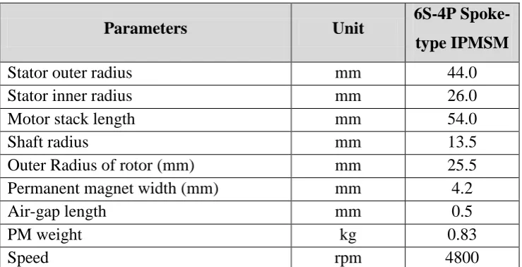
Table 1.1: Parameters of 6S-4P Spoke-type IPMSM.
Parameters Unit 6S-4P
Spoke-type IPMSM
Stator outer radius mm 44.0
Stator inner radius mm 26.0
Motor stack length mm 54.0
Shaft radius mm 13.5
Outer Radius of rotor (mm) mm 25.5
Permanent magnet width (mm) mm 4.2
Air-gap length mm 0.5
PM weight kg 0.83
Speed rpm 4800
1.5 Thesis Outline
This thesis consists of five chapters and the summary of each chapter is as follows: a) Introduction
The beginning chapter of this thesis gives some introduction regarding the research including the background of IPSM, problem of existing motors employing cogging torque effect, research objectives, and research scope. b) Literature Review
The second chapter is a literature review that summarises the basic theory of torque pulsation and cogging torque phenomenon in electrical machines. Various cogging torque minimisation techniques from previous research are discussed in detail and compared.
c) Research Methodology
machine analysis, which consists of open circuit and closed circuit analysis by 3D FEA.
d) Results and Discussion
The design and performance of conventional and proposed cogging torque reduction technique has been described in this chapter. To validate the performance of cogging torque reduction with various techniques, the design was analysed at open circuit and closed circuit conditions. Then, the best cogging torque reduction techniques is identified and the improvement of design and analysis of this design is discussed in this chapter.
e) Conclusion and Future work
2CHAPTER 2
LITERATURE REVIEW
2.1 Introduction
This chapter reviews the phenomena of cogging torque in PM motor and numerous studies of cogging torque reduction techniques in electrical motor. The phenomena of cogging torque in PMSM from the earliest to the latest study also been explained in this chapter. Furthermore, various methods for cogging torque reduction in PM motor together with their findings were elaborated. Finally, the pros and cons in terms of developed structure were also explained in brief at the end of this chapter.
2.2 Overview of Permanent Magnet Synchronous Motor (PMSM)
intrinsic characteristics make them suitable for sensorless drive applications [7]. The permanent magnet type motors are divided according to the location of the permanent magnet and is usually built with one of the following rotor configurations as shown in Figure 2.1 and Figure 2.2.
[image:28.595.151.492.166.304.2]Figure 2.1: Surface Permanent Magnet Synchronous Motor (a) Classical (with salient
poles), (b) Surface magnet rotor, and (c) Inset magnet rotor.
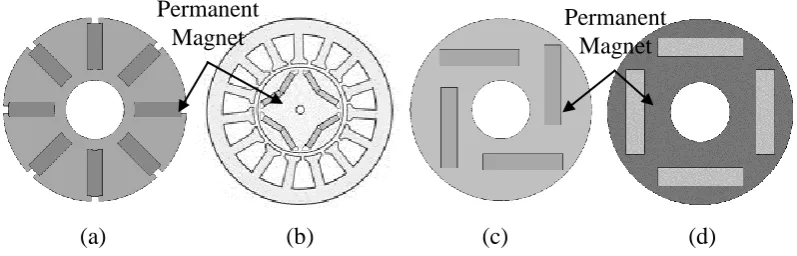
(a) (b) (c) (d)
Figure 2.2: Interior Permanent Magnet Synchronous Motor. (a) Spoke-type/interior transverse magnet rotor, (b) Split interior magnet rotor, (c) Interior magnet rotor, and
(d) Rotor with buried magnets asymmetrically distributed.
PMSMs can be designed with surface permanent magnets (SPMs) in which PMs are attached to the circumference of the rotor or with IPMs where the PM is placed inside the rotor core. Compared with SPMSM, IPMSM has been widely used because of their better performance in flux weakening operation and achieve higher flux density. This can be proven by the historical progress in the power density of the main traction motor installed on Toyota HEVs [8]. One advantage comes from the position of magnets. Because PMs are embedded in the rotor, the IPMSM can be utilised at higher speeds without de-bonding of the PM from the rotor due to the
(a) (b) (c) Permanent Magnet
Permanent Magnet
Permanent
[image:28.595.114.513.371.499.2]centrifugal forces. In addition to the mutual torque from the PM, the IPMSM utilises the reluctance torque generated by the rotor saliency.
Despite their great performances and being well-operated, IPMSMs have some drawbacks to be solved. Regarding the noise and vibration, IPMSMs have more sources than the SPM motors. Furthermore, analysis of magnetic field in the IPMSM is more difficult due to the magnetic saturations, especially in the rotors. In an IPM motor, the electromagnetic excitation sources can be classified into three parts: cogging torque, ripples of mutual, and reluctance torque, and fluctuations of radial attractive force between the rotor and stator. In an SPM motor, only the mutual torque is generally considered and an analytical method can be used.
Hence, the research for solving this problem is essentially demanded. The vibration sources on the motor are classified with causes of mechanical and electro-magnetic. The mechanical causes are rotation of the rotor, uneven distribution of mass within rotor, the balancing of the motor, the bearing defective, and so on. The electro-magnetic causes are an unbalance of electric source, the harmonic components of phase current, and an unbalance of air-gap, etc. The mechanical causes could be removed with the production, which is precise, and the revision after producing. The principal electro-magnetic causes are a problem in motor design especially in the case of IPMSM, which has the structure where the mechanical air-gap and magnetic air-gap are identical, therefore, the vibration and noise are larger by the cogging torque. The vibration and noise abrade the motor and decrease performance [9]. Accordingly, it is essential to embody low vibration and low noise.
2.3 Review of Cogging Torque
Torque quality in both radial and axial gap PM motors has been investigated by many researchers merely because of the benefits of the low-speed applications [11]. The torque pulsations are never considered as a serious issue at high speeds. On the other hand, it could generate major problems at low speed because of the motor-driven torque pulsations or the inverter-motor-driven pulsations. Generally, there are a few torque components in PM motors, out of which, average torque is considered as the main torque component. This average torque is usually caused by the interaction concerning the fundamental stator magnetomotive force (MMF) and the PM Field [12]. On the other hand, the stator MMF harmonics and the PM field interactions collectively produce a chiefly undesirable torque component termed torque ripple. The effects of the torque ripple could be severe based on the motor design and the source current harmonics. The foremost problem of torque ripple emerges at low speeds despite the fact that the system inertia filters out the torque pulsations at high speeds. There is another torque component known as reluctance torque, which is usually considered as part of torque ripple. This reluctance torque can be generated by the stator MMF, stator slotting, and anisotropy of the rotor.
Finally, another majorly undesirable torque component is known as cogging torque and this is generated by the interaction amongst the magnetic field and the stator slotting or it could be just caused by the air-gap reluctance variation. The prescribed value for average cogging torque must be zero and its variation can be obtained with no stator excitation in the coils [13].
[image:30.595.119.510.518.639.2]
(a) (b)
Figure 2.3: Flow path of flux. (a) Stable detent position, (b) Generating cogging torque.
cogging torque. While the magnetic flux travels through the rotor to the stator, reluctance shows variation inevitably. The path of the magnetic flux originates from the magnets and the rotor, and later it follows the air-gap and the stator; and then it returns in the same manner [14].
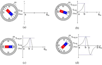
The circumferential component of attractive force attempts to maintain the alignment between the stator teeth and the permanent magnet poles [15]. Figure 2.4 indicates the four positions of the magnet pole with the stator teeth and one period of typical cogging torque waveform. In Figure 2.5(a), the PM is aligned in an unstable detent position. In this position, there is maximum air-gap space between the rotor and the stator. Thus, the maximum amount of air-gap reluctance exists and hence, the resultant cogging.
(a) (b)
[image:31.595.120.526.321.581.2](c) (d)
Figure 2.4: One period of a regular cogging torque cycle. (a) An unstable detent position, (b) A peak cogging torque position, (c) A stable detent position, and (d) An
unstable detent position [15].
By rule of thumb, one of the main requirements for a new motor design in an industry application is the desire for low torque ripples and low cogging torque. As a result, a good PM electric motor design should emphasise high amplitude torque output as well as reduction of cogging torque [16]. Specifically, for automobile applications, both the torque ripple and cogging torque should be lower than 5% and 0.5% of the nominal torque, respectively. Cogging torque, which can be called as the
c θm a ω τcog (Nm) θm a b
ω τcog (Nm) τcog.pk
θm a b
ω τcog (Nm) τcog.pk
θm b
a c d
detent torque, and ‘no-current’ torque act as disturbances as they superimpose over the electromagnetic torque that is produced during the operation of the machine operation. This could even produce zero networks. As discussed earlier, cogging torque could cause unacceptable vibrations, acoustic noise, poor position, pathetic speed control, performance degradation, and dangerous running failures. Cogging torque has also been found to be detrimental to the performance of position control systems such as robots and to the performance of speed control systems particularly at low speed. The interactions between PMs mounted on the rotor and the anisotropy originated by stator windings slots raised the cogging torque and variations of the magnetic field energy during the rotation, according to:
W m
cog
(2.1)
where τcog, δWm, and δϴ, are the cogging torque, energy in the air-gap, and angle of
rotor respectively. Cogging torque produces zero network, yet it acts as a disturbance, superimposing over electromagnetic torque created in the course of machine operation [17]. From the time when the cogging torque was caused by the interaction between the PM on the rotor and the stator slot openings, the cogging torque period has been linked with the number of slots and poles by:
N rN s
HCFN r
N p (2.2)
N r N s N p
Ne (2.3)
Ne refers to the number of cogging torque cycles, Np is constant, Nrrefers to the
number of rotor poles, and HCF is the highest common factor. The resulting cogging torque is the sum of the elementary torque produced by the interaction between each magnet and the edge of the slot opening [18]. Therefore, this clearly shows that a low value of Np will lead to high cogging torque while a high value of Npwill lead to a
kQm k
k
x
sin 1
(2.4)
Since the magnetic energy could be expressed as a function of permeance and squared MMF, many methods attempt to reduce the amplitude of the main harmonics by acting on one or both of these physical quantities, which defines the magnetic energy [19].
2.4 Cogging Reduction Method
Minimisation of cogging torque has always been a major concern in PM machine design, mainly for applications where low speed or position control is mandatory. Cogging torque is one of the main sources of torque and speed fluctuations in many applications. It is also a significant criterion for the superiority of the PM motor design. For that reason, cogging torque minimisation techniques can be separated into two leading categories: control-side methods and design-side methods. Control-side techniques are grounded on the harmonic current injection to eliminate the cogging component of the torque. Meanwhile the design-side methods generally are based on the design optimisation of the geometric parameters of the machine. Typically, the design-based techniques were considered to be more effective as well as economical than the control-based ones. The control-side methods invariably involved costly, reliable, and accurate sensors [20].
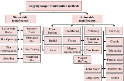
Cogging torque minimization methods Stator side modification Dummy Slots Stator Pole Ratio Rotor side modification Displaced Slot Slot Opening Rotor
Pairing Chamfering Notching Skewing
Classic Triangular Parallel Side Trapezoidal Radial Axial Round Dual Skew Magnet & Pole Arc Step Skew Flux barrier Slot Pairing Flange Magnet Optimization Slot Optimization Skewing Fractional
[image:34.595.116.525.68.335.2]Slot ShiftingMagnet
Figure 2.5: Cogging torque minimisation methods.
Basically, the stator side modification comprises the stator pole ratio [22]–[24], stator tooth pairing [25], slot opening [26]–[29], dummy slots [30], [31], and displacement slot [32]–[35]. In contrast, the rotor side modification consists of rotor pole radially and axially paired [36]–[38], chamfering [39][40], magnet pole arc [41]–[44], magnet shaping or shifting [45]–[47], skewing [48]–[53], flux barrier [54], and notching [57]–[62]. Modification in rotor side has been widely used compared with the stator part as it complicates the stator manufacturing and consequently increases the manufacturing cost of the machine. Therefore, modifications from the stator side were considered not to be practical in a majority of the machines and hence this approach was not preferred.
2.5.1 Skewing the Slots/Poles/Magnet
as conventional skew, triangular skew, parallel-sided skew, trapezoidal skew, circular skew, and dual-magnet skew. However, both sides have disadvantages. Skewing the PM increases the magnet cost and skewing the slot increases the copper loss due to increased slot length, resulting in longer wire. Skewing the rotor PM continuously is not convenient and even impractical for the prototype machine because of its bread loaf-shaped magnet poles. Therefore, skewing the rotor magnet stepwise is more preferable to ease fabrication and assembly. The skewing angle for this method is between two adjacent steps, which is equal to:
Q Nc n skewing
2 (2.5)
Where n is the number of skewing steps, Q is the number of stator slots, and Nc is the
period of cogging [31]. Various numbers of skew steps are analysed under no-load condition in [63].
(a) (b)
[image:35.595.161.477.388.674.2]
(c) (d)
Figure 2.6: Step-skew rotor design under open circuit condition (a) Two steps, (b) Three steps, (c) Four steps, and (d) Five steps [63].
are illustrated in waveforms as shown in Figure 2.7. The waveforms are ranging from two to five and the corresponding step skewing angles has been anticipated by 3D FEA and compared. The outcomes affirm that the cogging torque can be lessened adequately in the machine with conventional rotor step skewing method. Nonetheless, there are as yet evident fundamental harmonics in the cogging torque because of the considerations of the end impacts and axial interactions in the 3D FEA results. The cogging torque continuously drops as the number of step increased, and the machines with conventional skewing steps of four and five produces similar cogging torque waveforms.
Figure 2.7: Cogging torque waveform with different rotor skewing steps [63]. Furthermore, an experimental analysis of step skewed has been discussed in [64]. This technique was chosen due to their simplicity and simple implementation that also led to the reduction of PM eddy current losses. Skewing can be designed by placing the PM axially skewed by discrete steps, as illustrated in Figure 2.8. With the skewing angle between the adjacent sections and rotor of ±2.5 mechanical degrees, the cogging torque effect was reduced up to 54%.
Figure 2.8: Prototype of stepped rotor skewing [64]. 27
9 0 -9 -18 18
-27
0 5 10 15 20 25 30
C3-step (3D) C5-step (3D) C2-step (3D)
C4-step (3D)
Rotor Position [deg.e]
C
ogging Torque
(m.N
[image:36.595.225.412.589.724.2]Three cross sections of a PM machine with the stator core skewed by a skewing angle of α is shown in Figure 2.9 [65]. Stator skewing changed the relative position between the stator and rotor along the axial length of the machine. Therefore, the parameters of the machine were not constant along the motor axis as well as variation of magnetic field distribution. Taking into account, the skewing effect of the machine parameters were presented in 3-D function of the rotor position, θ and axial length of the machine. Therefore, the flux-linkage per length due to magnets of a PM machine with skewed stator or rotor topology can be described in this paper. Furthermore, skewing has the impact of enhancing stator windings distribution and significantly reduced higher order back-EMF harmonic, thus creating more sinusoidal back-EMF wave-shapes.
[image:37.595.133.511.308.458.2]
(a) (b) (c)
Figure 2.9: Cross sectional views of a PM machine at different axial-z location. (a) z= laxial / 2, (b) z= 0, and (c) z= laxial/ 2 [65].
2.5.2 Slot Opening Variation
Since cogging torque is generated by the interaction of the stator teeth and the rotor magnetic field, slot opening has an effect on the cogging torque. Various researchers are interested in this technique. For example, an analytical technique for accurately determining the optimal slot opening for minimum cogging torque in PM machines has been presented in [66]. Then, it was utilised to determine the relationship between slot opening and cogging torque for machines having different combinations of slot numbers and pole numbers, N. Levin in [67] also reduced the cogging torque effect using this technique as shown in Figure 2.10 and concluded that the wider
Stator u-axis
Rotor d-axis
-αskew /2
u u` u u`
Rotor q-axis Stator u-axis
Rotor q-axis
Rotor d-axis
αskew = 0
u
Stator u-axis
Rotor q-axis
Rotor d-axis
αskew /2
opening of slot, the greater value of cogging torque based on the graph in Figure 2.11.
Figure 2.10: Slot opening and PM interpolar distance [67].
Figure 2.11: Stepped rotor skewing with three modules [67].
However, it should be noted that the value of slot opening width is determined by industrial requirements and it depends on the cross section of armature conductors [68].
Basically, when the slot opening becomes smaller, the cogging torque and the harmonic content of the back-EMF decreases but the slot opening method suffers from a trade-off between cost and total rating usage. If the slot opening is minimum, the motor cannot be used to its full potential and only 70% of it can be utilised. Hence, minimal possible value of slot opening width needs to be considered to optimise the machine design.
Permanent magnet
Interpolar distance Slot Opening
Stator
Rotor
Slot Opening width, mm 4.0
3.5 3.0 2.5 2.0 1.5 1.0 0.5 0
Ma
xim
al cogging torque
,
Nm
[image:38.595.172.435.336.482.2]2.5.3 Stator tooth Pairing
The stator tooth pairing is a method by pairing the stator tooth with different size and width. The equation for optimal stator tooth pair width in which two paired stator tooth widths of a and b are presented in Equation 2.6, where n is constant and NL is the least common multiple of slots and PM numbers [69].
0 2 sin 2
[image:39.595.126.513.367.485.2] [image:39.595.159.443.536.732.2]sinnNLa nNLb (2.6)
Figure 2.12 shows the optimal stator tooth pairing and Figure 2.13 shows one cycle of the cogging torque according to the stator tooth paring design. The analysis result showed that the smallest cogging torque occurred at the combination of 6.5 [deg.(m)] to 11.5 [deg.(m)].
(a) (b)
Figure 2.12: Stator design (a) Conventional stator and (b) Stator tooth pairing [69].
Figure 2.13: Characteristic of cogging torque [69].
9.0-9.0 [deg.(m)] 7.6-10.4 [deg.(m)] 7.0-11.0 [deg.(m)] 6.5-11.5 [deg.(m)]
Rotor Rotation [deg.(e)]
0 15 30 45 60
Stator teeth pairing widths a and b
4 3 2 1 0 -1 -2 -3 -4 C ogging Torque [N m]
N S
Inner stator
Outer stator Rotor
N S Rotor
Outer stator Inner stator
N
N S
Two methods for reducing cogging torque in flux reversal machine, namely the segment rotor method and the stator poles pairing have been proposed in [70] and the cogging torque was successfully reduced. Daohan Wang, in [71] introduced a model for cogging torque mechanism and a Fourier analysis. Results verified that suitable considerations must be ensured to enhance the performance of a given technique. Since the cogging torque can be presented by partial differentiation, the expression to obtain an optimal tooth width was analysed in [72]. Based from the expansion, the cogging torque was reduced by 85%.
2.5.4 Rotor teeth/pole-pairing and Axial Pole Pairing
[image:40.595.248.389.562.713.2]Rotor teeth or pole pairing is similar to stator tooth pairing except that this method was applied in the rotor part of the machine. In this method, two different pole sizes or widths were assembled alternately in the rotor design in either radial or axial condition. This method requires an even number of rotor teeth to mechanically balance the motor. The variable magnetic resistance of air-gap and rotor not only changed the waveform of cogging torque, but was also reduced in the amplitude. The cogging torque waveform varied with the rotor tooth width, βr. As an example, if the width of all rotor teeth was set to 8o, the cogging torque has almost the same waveform as the case when the width at all rotor teeth was set to 11o, in opposite phase [73]. Therefore, two types of rotor teeth with different widths of βr at 8 and βr at 11, were alternatively employed as shown in Figure 2.14. Thus, the overall cogging torque can be significantly reduced by 13%, as verified by FEA results.
Figure 2.14: Rotor Teeth-Pairing [73]. βr = 8
An experimental result shows pairing rotor pole reduced the cogging torque by 85% along with an acoustic noise of 3.1 dB [74]. Meanwhile, a tooth pairing for an axial field flux-switching permanent magnet machine (AFFSPMM) was designed and analysed in [75]. Results showed that the cogging torque was reduced by 21% compared with the original design. The cogging torque comparison between tooth pairing design and the original design is shown in Figure 2.15. To obtain smaller amplitude of the cogging torque, it was also necessary to choose the proper width ratio of armature teeth to PM pole.
Figure 2.15: Cogging torque comparison between teeth pairing design and original design [75].
Another way of applying rotor teeth-pairing was by altering the stack length of design, corresponding to the magnitude of cogging as well as by changing the pole arc. The stacks length was fixed and only pole arc was varied so that cogging torque using axial pole arc pairing can be examined. It is a new technique to enable coils to be connected in parallel, and can comprise different axial lengths as well as different pole arc widths. Figure 2.16 shows the difference between rotor teeth circumferential pairing and rotor teeth axial pairing [76]. An improved pole pairing considering axial stack length using analytical formulas is proposed, which reduces the cogging torque by 71.98%. By selecting the optimal rotor pole arc and stack length, the effect of cogging torque not only can be reduced, but also results in improved harmonic content of the back-EMF.
1.5 1.0 0.5
-1.0 -1.5
-0.5
0
0 6 12 18 24 30 36 Teeth pairing Original
C
ogging Torque
(N
m)
(a) (b)
Figure 2.16: Rotor teeth pairing (a) Circumferential pairing and (b) Axial pairing [76].
2.5.5 Stator/rotor pole displacement design
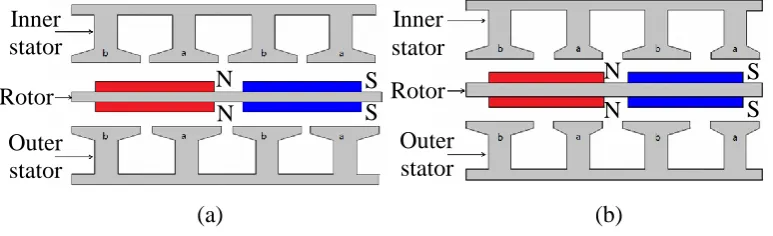
Stator and pole displacement design is normally applied with rotor or dual-stator machine. The objective of the dual-stator displacement design is to reduce the cogging torque by placing the inner and the outer stators in a staggered pattern as shown in Figure 2.17. An analytical expression as the sum of the total cogging torques can be made equal to zero by transitioning the cogging torque phase, which is generated in the outer stator, by 180° [77].
(a) (b)
Figure 2.18: Cogging torque characteristic for various stator displacement angle [77]. Since the Np and Nsof the machine in this study are 30 poles and 20 slots separately,
the optimal value of stator displacement was set to 30°. As a result, the cogging torque was reduced by 86.6% as shown in Figure 2.18.
Permanent magnet Inner Stator
Outer Stator
Rotor
[image:42.595.145.504.458.592.2]Figure 2.17: Stator displacement. (a) Original design and (b) Stator displacement design [77].
Furthermore, when the rotor pole staggered a little angle between two rotors as shown in Figure 2.19, the peak cogging torque on both sides of the stator staggered some angles too, which avoided the overlapping of the peak cogging torque [78]. Hence, the cogging torque was decreased. The influence of the rotor pole displacement angle on the cogging torque and the comparison of the cogging torque are shown in Figure 2.20. For the result, the minimum cogging torque was obtained when the rotor pole displacement angle equaled to 2 degrees. The cogging torque was reduced by 59%.
Figure 2.19: The rotor pole displacement between two rotors [78].
C
ogging t
orque
[N
m]
0 15 30 45 60 Rotor rotation [deg.(e)]
Stator displacement angle 0 [deg.(e)]
10 [deg.(e)] 20 [deg.(e)] 30 [deg.(e)]
40 [deg.(e)] 60 [deg.(e)] 50 [deg.(e)] 1
0 2 3 4
-1 -2
[image:43.595.208.430.526.680.2]Figure 2.20: Cogging torque comparison of two rotor designs [78].
2.5.6 Slot and pole number combination
Slot and pole number combinations play an important role in suppressing vibration and noise for low-speed PM machines [79]. Basically, the appropriate combination of the slot and pole number, magnet arc, and thickness can significantly reduce the cogging torque. The smaller the number of slots or poles and the larger the common multiple between the slot number Q and the pole number, the smaller the amplitude of the cogging torque [80].
Figure 2.21: The pole-pitch to pole-arc ratio of rotor PM [81].
In order to gain a relationship between the slot/pole combination and the torque ripple, air-gap field was analysed. An integer number of slots per pole and a fractional number of slots per pole can be treated. Moreover, the changes in the number of cycles depend on pole number and slot number combinations. In general,
Rotor pole displacement
No rotor pole displacement 1.5
1.0 0.5 0 -0.5 -1.5
-2.5 -2.0
Rotor pole position [mech. Deg]
0 2 4 6 8 10 12
C
ogging Torque
(N
m)
Permanent magnet
Pole Arc Pole pitch
αp Rotor
[image:44.595.214.426.503.635.2]the more the cycles, the smaller the cogging torque amplitude. As shown in Figure 2.21, the pole-arc ratio αp of rotor PM is p represented as in Equation 2.7 [81].
p m
p (2.7)
Where, τp is the rotor pole pitch and τm is the magnet pitch. The optimum magnet
pole-arc ratio a for the minimum αpo cogging torque in the radial field as in (2.8):
, 1,2.. 1 k N
N k N po
(2.8)
where, N = Nc /2, p is the pole pair number, Nc is LCM of the rotor pole numbers and
the stator slots numbers. Practically, the optimal value of αp would be a little larger
than the calculated p number because of the leakage flux of the stator [81].
2.5.7 Dummy Slot/Notching
6REFERENCES
[1] M. a. Tavakkoli and S. M. Madani, “A new approach to analysis and mitigation of PM motor cogging torque,” Proc. - 34th Annual Conference of IEEE on Industrial Electronic IECON 2008, vol. 1, pp. 2003–2008, 2008. [2] A Hartman and W. Lorimer, “Cogging Torque Control in Brushless DC
Motors,” Motion Control System Devies, vol. 2, no. 6, pp. 4287–4289, 2000. [3] Z. Q. Zhu and D. Howe, “Analytical prediction of the cogging torque in
radial-field permanent magnet brushless motors,” IEEE Transaction on Magnetic, vol. 28, no. 2, pp. 1371–1374, 1992.
[4] M. Aydin and T. a. Lipo, “Cogging torque minimization technique for multiple-rotor, axial-flux, surface-mounted-PM motors: alternating magnet pole-arcs in facing rotors,” 3 38th IAS Annual Meeting on Conference Record of the Industry Applications Conference, 2003, vol. 1, no. August 2016, pp. 555–561, 2003.
[5] Y. Yang, X. Wang, R. Zhang, T. Ding, and R. Tang, “The optimization of pole arc coefficient to reduce cogging torque in surface-mounted permanent magnet motors,” IEEE Transaction on Magnetic, vol. 42, no. 4, pp. 1135– 1138, 2006.
[6] I. Trifu and T. Tudorache, “Cogging Torque Optimization of a Four-Pole PM Machine,” 2013 8th International Symposium on Advanced Topics in Electrical Engineering (ATEE), no. 2, pp. 2068-7966, 2013.
[7] Y. Chun, D. Koo, Y. Cho, W. Cho, and a B. Structure, “Cogging Torque Reduction in a Novel Axial Flux PM Motor,” International Symposium on Power Electronics, Electrical Drives, Automation and Motion, 2006. SPEEDAM 2006. pp. 16–19, 2006.
[8] J. Wang, L. Zhou, T. Yang, and Y. Wang, “Cogging torque reduction in interior permanent magnet brushless dc motor with flux-concentration type rotor,” 2009 International Conference on Electrical Machine System, pp. 1–6, 2009.
[9] D. Xu, M. Lin, X. Fu, L. Hao, W. Zhang, and N. Li, “Cogging Torque Reduction of a Hybrid Axial Field Flux-Switching Permanent-Magnet Machine with Three Methods,” IEEE Transaction on Applied Superconductor, vol. 26, no. 4, pp. 4–8, 2016.
[10] D. Dorrell, “Design techniques in brushless permanent magnet motors,” IEEE Transaction on Magnetic, vol. 30, no. 6, pp. 4287–4289, 2010.
[12] R. Lateb, N. Takorabet, and F. Meibody-Tabar, “Effect of magnet segmentation on the cogging torque in surface-mounted permanent-magnet motors,” IEEE Transaction on Magnetic, vol. 42, no. 3, pp. 442–445, 2006. [13] J. M. Ling and T. Nur, “Influence of edge slotting of magnet pole with fixed
slot opening width on the cogging torque in inset permanent magnet synchronous machine,” The 2nd IEEE Conference on Power Engineering and Renewable Energy (ICPERE) 2014, vol. 8, no. 8, pp. 1–9, 2016.
[14] D. Wang, X. Wang, M. K. Kim, and S. Y. Jung, “Integrated optimization of two design techniques for cogging torque reduction combined with analytical method by a simple gradient descent method,” IEEE Transaction on Magnetic, vol. 48, no. 8, pp. 2265–2276, 2012.
[15] G. C. Lee and T. U. Jung, “Optimal cogging torque reduction design of dual stator radial flux permanent magnet generator,” 2 2013 15th European Conference on Power Electronics and Applications (EPE), vol. 1, 2013. [16] H. C. Yu, B. S. Yu, J. Te Yu, and C. K. Lin, “A dual notched design of
radial-flux permanent magnet motors with low cogging torque and rare earth material,” IEEE Transaction on Magnetic, vol. 50, no. 11, 2014.
[17] K. Abbaszadeh, F. R. Alam, and S. a. Saied, “Cogging torque optimization in surface-mounted permanent-magnet motors by using design of experiment,” Energy Conversion and Management., vol. 52, no. 10, pp. 3075–3082, 2011. [18] M. Aydin and M. Gulec, “Reduction of cogging torque in double-rotor
axial-flux permanent-magnet disk motors: A review of cost-effective magnet-skewing techniques with experimental verification,” IEEE Transaction on Industrial Electronic, vol. 61, no. 9, pp. 5025–5034, 2014.
[19] R. E. Hanitsch, M. S. Widyan, and R. Grune, “Cogging Torque Reduction of a Novel Low-Speed High-Energy Permanent-Magnet Electrical Machine,” International Symposium on Power Electronics, Electrical Drives, Automation and Motion, 2006. SPEEDAM 2006. pp. 1–6, 2006.
[20] G. S. Babu, T. M. Krishna, and B. V. Reddy, “A Comparative Analysis of Cogging Torque Reduction in BLDC Motor Using Bifurcation and Slot Opening Variation,” American Journal of Electrical Power and Energy Systems, Pages: 9-12 vol. 4, pp. 9–12, 2015.
[21] W. Zhao, T. a. Lipo, and B. Il Kwon, “Material-efficient permanent-magnet shape for torque pulsation minimization in SPM motors for automotive applications,” IEEE Transaction on Industrial Electronic, vol. 61, no. 10, pp. 5779–5787, 2014.
[22] Y. Pang, Z. Q. Zhu, and Z. J. Feng, “Cogging torque in cost effective surface mounted permanent magnet machines,” IEEE Transaction on Magnetic, vol. 47, no. 9, pp. 2269–2011, 2011.
83 [24] N. Diga, C. Ghita, C. Stoica, and S. M. Diga, “Particular aspects of the cogging torque reduction for permanent magnet synchronous motors using specialized software,” 2015 7th International Conference on Electronics, Computers and Artificial Intelligence (ECAI), pp. WF27–WF30, 2015.
[25] L. Hao, M. Lin, D. Xu, and W. Zhang, “Cogging Torque Reduction of Axial Field Flux-Switching Permanent Magnet Machine by Adding Magnetic Bridge in Stator Tooth,” IEEE Transaction on Applied Superconductor, vol. 24, no. 3, 2014.
[26] T. Liu, S. Huang, J. Gao, and K. Lu, “Cogging torque reduction by slot-opening shift for permanent magnet machines,” IEEE Transaction on Magnetic, vol. 49, no. 7, pp. 4028–4031, 2013.
[27] D. A. González, J. A. Tapia, and A. L. Bettancourt, “Design consideration to reduce cogging torque in axial flux permanent-magnet machines,” IEEE Transaction on Magnetic., vol. 43, no. 8, pp. 3435–3440, 2007.
[28] D. Wu and Z. Q. Zhu, “Design Trade-off between Cogging Torque and Torque Ripple in Fractional Slot Surface- Mounted Permanent Magnet Machines,” 2015 IEEE International Magnetics Conference (INTERMAG), vol. 15, no. 4, pp. 2015, 2015.
[29] R. Somanatham, P. V. N Prasad, A. D. Rajkumar, “Reduction of Cogging Torque in PMBLDC Motor with Reduced Stator Tooth Width and Burificated Surface Area using Finite Element Analysis.” 2011 1st International Conference on Electrical Energy Systems, vol. 40, pp. 128 - 132, 2011.
[30] A. L. I. Jabbari, “The Effect of Slot Skewing and Dummy Slots on Pulsating Torque Minimization in Permanent Magnet Brushless Dc Motors,” 2016 Iranian Conference on Renewable Energy & Distributed Generation (ICREDG), vol. 1, no. 2, pp. 404–409, 2014.
[31] T. Sebastian, “Issues in Reducing the Cogging Torque of Mass-produced Permanent Magnet Brushless DC Motor,” IEEE Transactions on Industry Applications, vol. 40, pp. 813 - 820, 2003.
[32] S. M. Hwang, J. B. Eom, Y. H. Jung, D. W. Lee, and B. S. Kang, “Various design techniques to reduce cogging torque by controlling energy variation in permanent magnet motors,” IEEE Transaction on Magnetic, vol. 37, no. 4 I, pp. 2806–2809, 2001.
[33] H. S. Ko and K. J. Kim, “Characterization of noise and vibration sources in interior permanent-magnet brushless DC motors,” IEEE Transaction on Magnetic, vol. 40, no. 6, pp. 3482–3489, 2004.
[34] W. Ren, Q. Xu, Q. Li, and L. Zhou, “Reduction of Cogging Torque and Torque Ripple in Interior PM Machines with Asymmetrical V-Type Rotor Design,” IEEE Transaction on Magnetic, vol. 52, no. 7, pp. 4–7, 2016.
[36] J. F. Gieras, “Analytical approach to cogging torque calculation in PM brushless motors,” IEEE Transactions on Industry Applications, vol. 2, no. 5, pp. 815–819, 2003.
[37] K. Seo, Y. Kim, and S. Jung, “Stator Teeth Shape Design for Torque Ripple Reduction in Surface-Mounted Permanent Magnet Synchronous Motor,” 2014 17th International Conference on Electrical Machines and Systems (ICEMS), pp. 387–390, 2014.
[38] R. Liu, R. Wang, and J. Li, “Reduction of cogging torque in surfacemounted permanent magnet brushless motor based on Motorsolve,” 2012 IEEE Innovation on Smart Grid Technology - Asia, ISGT Asia 2012, pp. 3–6, 2012. [39] X. Zhu, W. Hua, and M. Cheng, “Cogging Torque Minimization in
Flux-Switching Permanent Magnet Machines by Tooth Chamfering,” 2016 IEEE Energy Conversion Congress and Exposition (ECCE), pp.1-7, 2016.
[40] K. Yong-Su, K. Tae Heoung, K. Young Tae, O. Won Seok, and L. Ju, “Various design techniques to reduce cogging torque in flux-reversal machines,” 2005 International Conference on Electrical Machines and Systems, vol. 1, pp. 261–263 Vol. 1, 2005.
[41] L. Dosiek, “Cogging Torque Reduction in Permanent Magnet Machines,” IEEE Transactions on Industry Applications, vol. 43, no. 6, pp. 44–49, 2006. [42] W. Fei and P. C. K. Luk, “Cogging torque reduction techniques for axial-flux
surface-mounted permanent-magnet segmented-armature-torus machines,” 2008 IEEE International Symposium on Industrial Electronics, pp. 485–490, 2008.
[43] T. Tudorache, L. Melcescu, and M. Popescu, “Methods for cogging torque reduction of directly driven PM wind generators,” 2010 12th International Conference on Optimization of Electrical and Electronic Equipment, no. 1, pp. 1161–1166, 2010.
[44] S. Saravanan, M. A. N. Doss, S. Jeevananthan, and S. Vidyasagar, “Reduction of cogging torque by adopting semi circled permanent magnet,” 2011 1st International Conference on Electrical Energy Systems, no. 5, pp. 149–153, 2011.
[45] L. Wu, W. Jin, J. Ni, and J. Ying, “A cogging torque reduction method for surface mounted permanent magnet motor,” 2007 International Conference on Electrical Machines and Systems (ICEMS), vol. 2, no. 7, pp. 769–773, 2007. [46] T. Srisiriwanna and M. Konghirun, “A Study of Cogging Torque Reduction
Methods in Brushless Dc Motor,” 2012 9th International Conference on Electrical Engineering/Electronics, Computer, Telecommunications and Information Technology, pp. 1–4, 2012.
85 [48] D. C. Hanselman, “Effect of skew, pole count and slot count on brushless motor radial force, cogging torque and back EMF,”IEE Proceedings - Electric Power Applications, vol. 144, no. 5, p. 325, 1997.
[49] A. N. Patel and J. R. Patel, “Analysis of Cogging Torque Reduction by Increasing Stator Slot Depth in Brushless DC Motor,” 2016 IEEE 1st International Conference on Power Electronics, Intelligent Control and Energy Systems (ICPEICES), vol. 7, no. 10, pp. 1077–1082, 2014.
[50] L. Parsa and L. Hao, “Interior permanent magnet motors with reduced torque pulsation,” IEEE Transaction on Industrial Electronic, vol. 55, no. 2, pp. 602– 609, 2008.
[51] M. Aydin, “Magnet skew in cogging torque minimization of axial gap permanent magnet motors,” 2008 18th International Conference on Electrical Machines, pp. 1–6, 2008.
[52] M. Łukaniszyn, M. JagieŁa, and R. Wróbel, “Optimization of permanent magnet shape for minimum cogging torque using a genetic algorithm,” IEEE Transaction on Magnetics, vol. 40, no. 2 II, pp. 1228–1231, 2004.
[53] W. Fei, P. Chi, K. Luk, S. Member, J. Shen, and S. Member, “ Torque Analysis of Permanent Magnet Flux Switching Machine with Rotor Step Skewing,” IEEE Transactions on Magnetics, vol. 48, no. 10, pp. 2664–2673, 2012.
[54] Y. Kawaguchi, T. Sato, I. Miki, and M. Nakamura, “A Reduction Method of Cogging Torque for IPMSM,” 2005 International Conference on Electrical Machines and Systems, pp. 248–250, 2005.
[55] L. Fang, S.-O. Kwon, T. Sun, and J.-P. Hong, “Optimal shape design of double-barriers in single-layer interior PM synchronous motor for reducing torque pulsation,” 2010 International Conference on Electrical Machines and Systems, no. 5, pp. 1239–1241, 2010.
[56] L. Fang, S. Il Kim, S. O. Kwon, and J. P. Hong, “Novel double-barrier rotor designs in interior-PM motor for reducing torque pulsation,” IEEE Transaction on Magnetics, vol. 46, no. 6, pp. 2183–2186, 2010.
[57] H. U. Kim, Y. B. Kim, and P. S. Shin, “A Notch Shape Optimization of IPMSM Rotor Surface for Cogging Torque Reduction by PSO Method with FEM,” 2013 International Conference on Electrical Machines and Systems (ICEMS), pp. 1118–1121, 2013.
[58] G. Kang, S. Member, Y. Son, and G. Kim, “A Novel Cogging Torque Reduction Method for Interior Type Permanent Magnet Motor,” IEEE Transactions on Industry Applications, vol. 45, pp. 119–125,2009.
[59] S. Lee, K. Han, H. Ahn, G. Kang, Y. Son, and G. Kim, “A Study on Reduction of Vibration Based on Decreased Cogging Torque for Interior Type Permanent Magnet Motor,” 2008 IEEE Industry Applications Society Annual Meeting, vol. 1, pp. 6–11, 2008.
[61] W. H. W. Hua and M. C. M. Cheng, “Cogging torque reduction of flux-switching permanent magnet machines without skewing,” 2008 International Conference on Electrical Machines and Systems, vol. 2, pp. 3020–3025, 2008. [62] G. H. Kang, J. Hur, W. B. Kim, and B. K. Lee, “The shape design of interior
type permanent magnet BLDC motor for minimization of mechanical vibration,” 2 2009 IEEE Energy Conversion Congress and Exposition, pp. 2409–2414, 2009.
[63] W. Fei and Z. Q. Zhu, “Comparison of cogging torque reduction in permanent magnet brushless machines by conventional and herringbone skewing techniques,” IEEE Transaction on Energy Conversion, vol. 28, no. 3, pp. 664– 674, 2013.
[64] V. Grǎdinaru, L. Tutelea, and I. Boldea, “25 kW, 15 krpm, 6/4 PMSM: Optimal design and torque pulsation reduction via FEM,” 11th International Conference of Optimization Electric Electronic Equipment, OPTIM 2008, pp. 249–256, 2008.
[65] G. Dajaku and D. Gerling, “Skewing Effect on the PM Flux-Linkage High Harmonics of the PM Machines with Delta Winding,” 2009 13th European Conference on Power Electronics and Applications, pp. 1–7, 2009.
[66] Z. Li, S. Jiang, Z. Z. Qiang, and C. Chan, “Optimal slot opening in permanent magnet machines for minimum cogging torque,” IEEE Transactions on Magnetics, no. 3, pp. 1–5, 2011.
[67] N. Levin, S. Orlova, V. Pugachov, B. Ose-Zala, and E. Jakobsons, “Methods to Reduce the Cogging Torque in Permanent Magnet Synchronous Machines,” IECON 2016 42nd Annual Conference of the IEEE Industrial Electronics Society, vol. 19, no. 1, pp. 23–26, 2013.
[68] C. Bianchini, F. Immovilli, E. Lorenzani, A. Bellini, and M. Davoli, “Review of design solutions for internal permanent-magnet machines cogging torque reduction,” IEEE Transaction on Magnetic, vol. 48, no. 10, pp. 2685–2693, 2012.
[69] G.-C. Lee and T.-U. Jung, “Design of dual structural axial flux permanent magnet generator for small wind turbine,” TENCON Spring Conference 2013 (IEEE), vol. 8, no. 6, pp. 90–94, 2013.
[70] W. Fei and P. C. K. Luk, “A new technique of cogging torque suppression in direct-drive permanent-magnet brushless machines,” IEEE Transaction of Industry Application, vol. 46, no. 4, pp. 1332–1340, 2010.
[71] D. Wang, X. Wang, and S. Jung, “Design Techniques for Reducing Cogging Torque in Permanent Magnet Flux Switching Machine,” 2014 17th International Conference on Electrical Machines and Systems (ICEMS), vol. 18, no. 3, pp. 361–364, 2013.
87 [73] T. Yabumi, “Reduction of Cogging Torque in Permanent Magnet Motors,” J
Magn. Soc. Japan, vol. 31, no. 1, pp. 23–30, 2007.
[74] Sang-Moon Hwang, Jae-Boo Eom, Geun-Bae Hwang, Weui-Bong Jeong, and Yoong-Ho Jung, “Cogging torque and acoustic noise reduction in permanent magnet motors by teeth pairing,” IEEE Transaction of Magnetic, vol. 36, no. 5, pp. 3144–3146, 2000.
[75] L. Hao, M. Lin, D. Xu, N. Li, and W. Zhang, “Analysis of Cogging Torque Reduction Techniques in Axial-Field Flux-Switching Permanent-Magnet Machine,” IEEE Transaction Application in Superconductor, vol. 26, no. 4, 2016.
[76] Y. Wang, M. J. Jin, W. Z. Fei, J. X. Shen, Y. W. M. J. Jin, and W. Z. F. J. X. Shen, “Cogging torque reduction in permanent magnet flux-switching machines by rotor teeth axial pairing,” IET Electrical Power Appication., vol. 4, no. 7, p. 500, 2010.
[77] G. C. Lee and T. U. Jung, “Cogging torque reduction design of dual stator radial flux permanent magnet generator for small wind turbine,” IEEE 2013 Tencon - Spring, TENCON Spring 2013, pp. 85–89, 2013.
[78] L. Hao, M. Lin, D. Xu, W. Zhang, and N. Li, “Rotor design techniques for reducing the cogging torque in a novel dual-rotor axial field flux-switching permanent magnet machine,” 2014 17th Int. Conf. Electr. Mach. Syst. ICEMS 2014, pp. 1581–1586, 2015.
[79] Q. He and Q. Wang, “Design techniques for reducing cogging torque in low-speed permanent magnet wind power generator,” 2011 International Conference of Electrical Machine System, pp. 1–3, 2011.
[80] S. Hemmati, S. Member, S. Shokrikojoori, R. Ghobadi, S. Member, and M. I. Ghiasi, “A Practical Approach to Cogging Torque Reduction In a Permanent Magnet Synchronous Motor Using Non-dominated Sorting Genetic Algorithm,” 4th Annual International Power Electronics, Drive Systems and Technologies Conference, pp. 0–4, 2013.
[81] G.-C. Lee, S.-M. Kang, and T.-U. Jung, “Permanent magnet structure design of outer rotor radial flux permanent magnet generator for reduction cogging torque with design of experiment,” 2013 International Conference on Electrical Machines and Systems (ICEMS), pp. 315–319, 2013.
[82] W. Xu, J. Zhu, Y. Zhang, and J. Hu, “Cogging torque reduction for radially laminated flux-switching permanent magnet machine with 12/14 poles,” IECON Proc. (Industrial Electronic Conference, pp. 3590–3595, 2011.
[83] G. Zhang, W. Fengxiang, and S. Yongshan, “Reduction of rotor loss and cogging torque of high speed PM machine by stator teeth notching,” Proceeding International Conference in Electrical Machine System ICEMS 2007, no. 1, pp. 856–859, 2007.
[85] M. Nakano and Y. Morita, “Reduction of Cogging Torque Due to Production Tolerances of Rotor by Using Partially Placed Dummy Slots in Axial Direction,” IEEE Transactions on Industry Applications, vol. 51, no. 1, pp. 5579–5586, 2014.
[86] L. Zhu, S. Z. Jiang, Z. Q. Zhu, and C. C. Chan, “Analytical methods for minimizing cogging torque in permanent-magnet machines,” IEEE Transaction on Magnetic, vol. 45, no. 4, pp. 2023–2031, 2009.
[87] J. H. Hu, L. Wang, J. B. Zou, and B. Zhao, “Cogging torque reduction of hybrid excitation flux switching motor,” 5th International. Conference on Instrument Measurement Computer and Communication Control. IMCCC 2015, vol. 2, no. 5, pp. 1889–1892, 2015.
[88] N. Bianchi and S. Bolognani, “Design techniques for reducing the cogging torque in surface-mounted PM motors,” IEEE Transaction on Industrial Application., vol. 38, no. 5, pp. 1259–1265, 2002.
[89] T. Liu, S. Huang, and J. Gao, “A Method for Reducing Cogging Torque by Magnet Shifting in Permanent Magnet Machines,” 2010 International Conference on Electrical Machines and Systems, no. 50907020, pp. 2–5. [90] V. Keloth, M. Mijas, P. a. Manu, P. Thomas, V. M. Menon, and R. P. Praveen,
“Analysis of cogging torque reduction techniques of a slotless PMBLDC motor,” 2 2014 Annual International Conference on Emerging Research Areas: Magnetics, Machines and Drives (AICERA/iCMMD), pp. 1-7,2014. [91] P. S. Shin, S. H. Woo, Y. Zhang, and C. S. Koh, “An application of Latin
hypercube sampling strategy for cogging torque reduction of large-scale permanent magnet motor,” IEEE Transaction on Magnetic, vol. 44, no. 11 PART 2, pp. 4421–4424, 2008.
[92] C. a. Borghi, D. Casadei, A. Cristofolini, M. Fabbri, and G. Serra, “Application of a multiobj active minimization technique for reducing the torque ripple in permanent-magnet motors,” IEEE Transaction Magnetic., vol. 35, no. 5, pp. 4238–4246, 1999.
[93] J. Wanjiku, M. a. Khan, P. S. Barendse, and P. Pillay, “Influence of Slot Openings and Tooth Profile on Cogging Torque in Axial-Flux PM Machines,” IEEE Transaction on Industry Electronic, vol. 62, no. 12, pp. 7578–7589, 2015.
[94] O. Kudrjavtsev and A. Kilk, “Cogging Torque Reduction Methods,” 2014 Electric Power Quality and Supply Reliability Conference (PQ), pp. 251-254. [95] K. Abbaszadeh, F. Rezaee Alam, and M. Teshnehlab, “Slot opening
optimization of surface mounted permanent magnet motor for cogging torque reduction,” 2011 1st International Electric Drives Production Conference, vol. 55, pp. 108–115, 2012.
![Figure 2.6: Step-skew rotor design under open circuit condition (a) Two steps, (b) Three steps, (c) Four steps, and (d) Five steps [63]](https://thumb-us.123doks.com/thumbv2/123dok_us/8753848.892493/35.595.161.477.388.674/figure-step-rotor-design-circuit-condition-steps-steps.webp)
![Figure 2.7: Cogging torque waveform with different rotor skewing steps [63].](https://thumb-us.123doks.com/thumbv2/123dok_us/8753848.892493/36.595.225.412.589.724/figure-cogging-torque-waveform-different-rotor-skewing-steps.webp)
![Figure 2.9: Cross sectional views of a PM machine at different axial-z location. (a) z= laxial / 2, (b) z= 0, and (c) z= laxial / 2 [65]](https://thumb-us.123doks.com/thumbv2/123dok_us/8753848.892493/37.595.133.511.308.458/figure-cross-sectional-machine-different-location-laxial-laxial.webp)
![Figure 2.11: Stepped rotor skewing with three modules [67].](https://thumb-us.123doks.com/thumbv2/123dok_us/8753848.892493/38.595.236.399.138.285/figure-stepped-rotor-skewing-modules.webp)