i
EFFECT OF ARGENTUM ON DEVELOPMENT AND PROPERTIES OF COMPOSITE CATHODE La0.6Sr0.4Co0.2Fe0.8O3-δ – SDCC-Ag FOR LOW
TEMPERATURE SOLID OXIDE FUEL CELL (LTSOFC)
MUHAMAD SUBRI BIN ABU BAKAR
A thesis submitted in fulfilment of the requirement for the award of the Master’s Degree of Mechanical Engineering with Honours
Faculty of Mechanical and Manufacturing Engineering Universiti Tun Hussein Onn Malaysia
iii
Specially dedicated to:
My father and mother,
Mr. Abu Bakar Bin Ishak and Mrs. Romlah Binti Ismail, There’s no love and sacrifices like yours,
And nobody can replace both of you,
And yet not even a single word can be expressed to thank all of your kindness towards me.
My wife and daughter,
Syazwan Liyana and Husna Hazeera,
With Allah’s will, your love, supports and motivations makes me strong and move forwards,
Thanks for all your times, sacrifices, kindness and your sincere help, I’m so glad that I have both of you.
My beloved brothers and the only sister, Aminuddin, Kaharuddin, Hamzah and Rosnah, Thanks for all your encouragement, advices and guidance,
And for always be there for supporting me.
All my colleagues,
iv
ACKNOWLEDGEMENT
With the name of Allah, the most Generous and the most Merciful. I would like to thank Allah for giving me strength, courage, wisdom and knowledge to face all the difficulties and hardship in completing this master’s project.
Besides, a highest appreciation is especially dedicated to the most respective supervisor, Prof. Madya Dr. Sufizar Binti Ahmad for your supports, motivations, encouragements, tolerates, sacrifices, valuable assistances and kindness. A lot of thanks goes to my co-supervisors, Prof. Madya Dr. Hamimah Binti Abd.Rahman and Prof. Dr. Andanastuti Binti Muchtar for their supports, encouragement, and willingness to provide valuable assistance, suggestion, knowledgement and help during the accomplishment of my thesis.
Secondly, a note of thanks is given to my beloved parents for all their moral and financial supports, endless love and the encouragement. There is no doubt, their love and support are the valuable gift granted to me in my life.
A heartfelt appreciation to Jabatan Kejuruteraan Bahan dan Rekabentuk (JKBR) especially to Polymer and Ceramics Laboratory for allowing me to use the apparatus and equipment in the laboratory and providing me some space for lab work. Not forgotten, this thanks also dedicated to Mr. Fazlannuddin Hanur Bin Harith and Mr. Anuar Bin Ismail for their cooperation and willingness to guide and helping me in conducting some devices and machines.
Lastly, I would like to thanks to anyone who is involved either directly or indirectly in this project. I realized that without the involvement of various parties, this project is impossible to complete within the prescribe time. May Allah’s bless
v
ABSTRACT
vi
ABSTRAK
Merendahkan suhu pengoperasian sel fuel oksida pepejal (SOFC) menjadi tumpuan kajian masa kini. Dewasa kini, kajian terhadap bahan katod tertumpu kepada katod komposit berkarbonat dengan penambahan Argentum (Ag) yang memberikan prestasi cemerlang pada suhu pengoperasian rendah. Kajian ini menumpu kepada kesan kehadiran Ag terhadap pembangunan dan sifat katod komposit Lanthanum Strontium Cobalt Ferrite-Samarium Doped Ceria Carbonate-Argentum (SDCC-Ag) bagi aplikasi SOFC bersuhu rendah. Serbuk katod komposit LSCF-SDCC-Ag dengan penambahan Ag 1-5 wt.% dibangunkan dengan kaedah pengisaran bebola berhalaju tinggi (HEBM) dan disinter pada suhu 500-600˚C. Pencirian serbuk katod komposit melibatkan analisis pembelauan sinar-X (XRD) bagi menentukan keserasian kimia dan struktur kristalit serbuk katod komposit. Morfologi dan serakan unsur serbuk katod komposit diperhatikan melalui mikroskop elektron pengimbas pancaran medan (FESEM) dan analisis spektroskopi serakan tenaga (EDS). Analisis sifat-sifat fizikal seperti saiz partikel, saiz kristalit, keliangan dan keratan rentas pelet telah dijalankan. Sifat-sifat termal seperti pekali pengembangan terma (TEC) dan termogravimetri (TG) juga telah ditentukan. Kerintangan pelet katod komposit telah diukur menggunakan kaedah pengujian elektrik 2-prob pada suhu pengujian 400-600˚C. Semua katod komposit dengan penambahan Ag 1-5wt.% dan disinter pada suhu 500-600˚C menunjukkan keserasian kimia yang baik kerana tiada kehadiran juzuk baru yang dikesan melalui sensitiviti XRD. Fasa karbonat juga mampu dikekalkan oleh katod komposit setelah dipastikan melalui analisis transformasi Fourier inframerah (FTIR) dan TG. Saiz kristalit dan saiz partikel telah bertambah dengan pertambahan Ag manakala keliangan telah berkurang disebabkan pertambahan Ag dan juga suhu pensinteran. LSCF-SDCC-Ag 5wt.% disinter pada 600˚C, 2wt.%, disinter pada 550˚C dan 3wt.% disinter pada 600˚C mencatatkan purata nilai TEC yang paling hampir dengan SDCC iaitu peratus perbezaan TEC katod-elektrolit masing-masing sebanyak 0.3%, 3.0% dan 4.5% manakala suhu pensinteran 550˚C menunjukkan purata nilai TEC yang konsisten dan hampir antara katod komposit SDCC-Ag dengan elektrolit SDCC. Katod komposit LSCF-SDCC-Ag (2 wt.%) disinter pada 550˚C menghasilkan kerintangan yang paling rendah iaitu (0.61Ω) dan mempunyai lingkungan purata nilai TEC (9.74±4.98 (10 -6
viii
CONTENTS
TITLE i
DECLARATION ii
DEDICATION iii
ACKNOWLEDGEMENT iv
ABSTRACT v
ABSTRAK vi
CONTENTS vii
LIST OF TABLES xi
LIST OF FIGURES xii
LIST OF SYMBOLS/ xviii
ABBREVIATIONS
LIST OF APPENDICES xxi
CHAPTER 1 INTRODUCTION 1
1.1 Background of study 1
1.2 Problem statement 3
1.3 Objectives 4
1.4 Scopes of study 5
1.5 Significant of study 6
CHAPTER 2 LITERATURE REVIEW 7
2.1 Introduction 7
2.2 Fuel cell 7
viii
2.4 Solid oxide fuel cell (SOFC) 10 2.4.1 Advantages of SOFC 11 2.4.2 Operating principles of SOFC 13
2.4.3 Designs of SOFC 14
2.4.3.1 Tubular geometry 14 2.4.3.2 Planar geometry 15 2.5 Low Temperature Solid Oxide Fuel Cell 16
(LTSOFC)
2.6 Cathode for LTSOFC 18
2.6.1 Properties for cathode 19 2.6.2 Lanthanum Strontium Cobalt Ferrite 21
(La1-xSrxCo1-yFeyO3-δ) (LSCF)
2.7 LSCF composite cathode for LTSOFC 23 2.7.1 Electrochemical properties and 24
performance of LSCF composite cathode
2.7.1.1 Influence of SDC ceria- 24 electrolyte
2.7.1.2 Influence of GDC ceria- 27 electrolyte
2.8 Influence of metallic elements in LSCF 29 composite cathode
2.8.1 Silver (Ag) 30
2.8.2 Palladium (Pd) 32
2.8.3 Platinum (Pt) 33
2.9 Factors influencing the electrical 34 properties of composite cathode LSCF
2.9.1 Properties of starting powder/ 34 material
2.9.2 Amount of Ag addition 35 2.9.3 Variable in sintering temperature 36
ix
CHAPTER 3 METHODOLOGY 38
3.1 Introduction 38
3.2 Raw materials 40
3.3 Experimental procedure 42
3.3.1 Preparation of SDC carbonate 42 (SDCC) powder
3.3.2 Preparation of composite cathode 43 powder LSCF-SDCC
3.3.3 Preparation of composite cathode 45 powder LSCF-SDCC-Ag
3.3.4 Samples preparation of composite 46 cathode pellets LSCF-SDCC-Ag
3.3.5 Sample preparation for thermal 47 expansion coefficient (TEC) analysis
3.4 Characterization of composite cathode 48 LSCF-SDCC-Ag
3.4.1 X-Ray diffraction analysis (XRD) 48 and crystallite size measurement
via Scherrer’s equation
3.4.2 Fourier-transform infra-red analysis 51 (FTIR)
3.4.3 Field emission scanning electron 52 microscopy (FESEM) and particle
size measurement via SmartTiff software
3.4.4 SEM-energy dispersion x-ray 53 spectroscopy (SEM-EDS) and
cross section of composite cathode pellets via SEM
3.4.5 Porosity measurement via 54 Archimede’s method
x
3.4.7 Thermal expansion coefficient 57 (TEC) measurement
3.4.8 2-point probe electrical test to 57 measure resistance (Ω)
CHAPTER 4 RESULTS AND DISCUSSIONS 63
4.1 Introduction 63
4.2 Chemical compatibility on composite 64 cathode LSCF-SDCC-Ag
4.3 The existence of carbonate phase in 69 composite cathode LSCF-SDCC-Ag via
FTIR analysis
4.4 Morphology of composite cathode 71 LSCF-SDCC-Ag
4.5 Particle size of composite cathode powder 74 LSCF-SDCC-Ag
4.6 Crystallite size of LSCF, SDCC and Ag 76 4.7 Porosity of composite cathode 78
LSCF-SDCC-Ag
4.8 Elements distribution of composite cathode 88 LSCF-SDCC-Ag
4.9 Thermogravimetric (TG) analysis 95 4.10 Resistance of composite cathode 99
LSCF-SDCC-Ag
4.11 Thermal expansion coefficient (TEC) 104
CHAPTER 5 CONCLUSIONS 107
5.1 Conclusions 107
5.2 Recommendations 109
xi
LIST OF TABLES
2.1 Properties of LSCF-SDC composite cathodes for 25 intermediate to low temperature (800-500˚C) SOFC
2.2 Properties of LSCF-GDC composite cathodes for 27 intermediate to low temperature (800-500˚C) SOFCs
3.1 Specifications of the purchasing commercial powders 40
3.2 List of materials and equipments 41
3.3 Sample designation of composite cathode 62 LSCF-SDCC-Ag (1-5 wt.%)
4.1 Average particle size of composite cathode powder 75 LSCF-SDCC-Ag based on different amount of
Ag addition
4.2 Average of TEC value in the range of 30˚C – 700˚C 105
xii
LIST OF FIGURES
2.1 Schematic of the working principle of SOFC. Tubular 13 SOFC are used for illustrative purposes
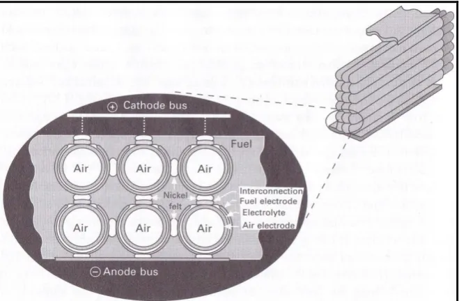
2.2 Schematic of cell-to-cell connection in a cathode- 15 supported tubular SOFC stack
2.3 Schematic of cell configuration in an anode-supported 16 planar SOFC stack
2.4 Figure 2.4: Schematic diagram of the (a) electrode 21 surface path, (b) the bulk path, and (c) the electrolyte
surface path (where O2 – oxygen gas Oad – adsorption oxygen O2- - oxygen ion)
2.5 Unit cell of the ABO3 perovskite structure 22
2.6 SEM images of the cathode-electrolyte interfaces of 31 (a) LSCF-SDC-Ag/SDC (b) LSCF-SDC/SDC
3.1 Development of composite cathode LSCF-SDCC-Ag 39 cathode for solid LTSOFC applications
3.2 Calcinations profile of SDCC powder 43
xiii
3.4 Calcinations profile of LSCF-SDCC powder 45
3.5 Composite cathode pellets LSCF-SDCC-Ag 46
3.6 Rod shape samples for TEC measurements 47
3.7 Bruker D8 Advance X-ray diffractometer 49
3.8 The sample preparation for SDCC electrolyte and 50 LSCF-SDCC-Ag composite powders
3.9 Powder diffractometer 50
3.10 Spectrum 100 FTIR spectroscopy 52
3.11 Field emission scanning electron microscope 52 JEOL JSM 7600F
3.12 Scanning electron microscop (SEM) coupled 54 with EDS analysis
3.13 Samples of different percentage of Ag amount 55 are immersed in iso-propanol
3.14 Electronic balance with density kit 55
3.15 Thermogravimetric Linseis analyzer 56
3.16 Silver conductive paint 58
xiv
3.18 Pellets are placed between the platinum wire 59 and alumina cube in sequence(more clearly
of illustration is shown through the schematic diagram)
3.19 The placement of the sample holder in quartz tube 60
3.20 Tube furnace used to heat the samples up to 600˚C 60
3.21 The setup for the resistance measurement of composite 61 cathode pellet
4.1 XRD spectra of LSCF-SDCC powder before and after 65 calcination at 750˚C
4.2 XRD spectra of LSCF-SDCC and LSCF-SDCC-Ag 66 (1-5 wt.%) sintered at 500°C
4.3 XRD spectra of LSCF-SDCC without Ag and with Ag 67 (1-5 wt.%) sintered at 550°C
4.4 XRD spectra of LSCF-SDCC without Ag and with Ag 67 (1-5 wt.%) sintered at 600°C
4.5 FTIR spectrum for (Li/Na)2CO3, SDCC after 69
calcinations at 680˚C, LSCF-SDCC after
calcinations at 750˚C and LSCF-SDCC-Ag
(1wt.%) after calcinations at 750˚C
xv
4.7 FESEM micrograph of composite cathode LSCF- 72 SDCC (a) without Ag, (b) Ag 1 wt.% and (c) Ag
2 wt.% with 50k magnification
4.8 FESEM micrograph of composite cathode LSCF- 73 SDCC (d) Ag 3 wt.% (e) Ag 4 wt.% and
(f) Ag 5 wt.% with 50k magnification
4.9 Measurement of particle size on composite 74 cathode powder LSCF-SDCC-Ag (1wt.%)
4.10 The change of LSCF crystallite size effects from 76 different amount of Ag addition and sintering
temperature of composite cathode LSCF-SDCC-Ag
4.11 The change of SDCC crystallite size effects from 77 different amount of Ag addition and sintering
temperature of composite cathode LSCF-SDCC-Ag
4.12 The change of Ag crystallite size effects from 77 different amount of Ag addition and sintering
temperature of composite cathode LSCF-SDCC-Ag
4.13 The influence of sintering temperature and amount 79 of Ag addition in cathode pellets LSCF-SDCC-Ag
4.14 Backscattered SEM micrograph for the cross section of 80 composite cathode pellets after sinter at 500˚C for
(a) without Ag (b) 1 wt.% Ag and (c) 2 wt.% Ag
4.15 Backscattered SEM micrograph for the cross section of 81 composite cathode pellets after sinter at 500˚C for
xvi
4.16 Backscattered SEM micrograph for the cross section of 82 composite cathode pellets after sinter at 550˚C for
(a) without Ag (b) 1 wt.% Ag and (c) 2 wt.% Ag
4.17 Backscattered SEM micrograph for the cross section of 83 composite cathode pellets after sinter at 550˚C for
(d) 3 wt.% Ag (e) 4 wt.% Ag and (f) 5 wt.% Ag
4.18 Backscattered SEM micrograph for the cross section of 84 composite cathode pellets after sinter at 600˚C for
(a) without Ag (b) 1 wt.% Ag and (c) 2 wt.% Ag
4.19 Backscattered SEM micrograph for the cross section of 85 composite cathode pellets after sinter at 600˚C for
(d) 3 wt.% Ag (e) 4 wt.% Ag and (f) 5 wt.% Ag
4.20 Backscattered SEM micrograph for the cross section of 87 composite cathode pellets LSCF-SDCC-Ag (2 wt.%)
sintered at (a) 500˚C (b) 550˚C and (c) 600˚C
4.21 Mapping and spectrum EDS illustrates elements 89 distribution in composite cathode LSCF-SDCC
without Ag addition
4.22 Mapping and spectrum EDS illustrates elements 90 distribution in composite cathode LSCF-SDCC-Ag
(1 wt.%)
4.23 Mapping and spectrum EDS illustrates elements 91 distribution in composite cathode LSCF-SDCC-Ag
xvii
4.24 Mapping and spectrum EDS illustrates elements 92 distribution in composite cathode LSCF-SDCC-Ag
(3 wt.%)
4.25 Mapping and spectrum EDS illustrates elements 93 distribution in composite cathode LSCF-SDCC-Ag
(4 wt.%)
4.26 Mapping and spectrum EDS illustrates elements 94 distribution in composite cathode LSCF-SDCC-Ag
(5 wt.%)
4.27 TG-Curve for Li2CO3, Na2CO3 and SDCC 96
4.28 TG-Curve for LSCF-SDCC-Ag (1-5wt.%) 98
4.29 Resistance of composite cathode LSCF-SDCC 99 without Ag addition
4.30 Resistance of composite cathode 100 LSCF-SDCC-Ag (1wt.%)
4.31 Resistance of composite cathode 100 LSCF-SDCC-Ag (2wt.%)
4.32 Resistance of composite cathode 101 LSCF-SDCC-Ag (3wt.%)
4.33 Resistance of composite cathode 101 LSCF-SDCC-Ag (4wt.%)
xviii
LIST OF SYMBOLS/ABBREVIATIONS
e- - electron
Ea - activation energy
H+ - proton kW - kilo watt Mw - mega watt I - current V - volt
λ - wave length CuKα σ - conductivity
θ - Bragg’s diffraction angle
O2- - oxygen ion O2 - oxygen gas H2O - water
CO2 - carbon dioxide CO32- - carbonate P - power Ni - nickel Cu - cuprum R - resistance
Rp - polarization resistance S - active surface area V - volt
𝑊𝑤 - wet weight of pellets in air 𝑊𝑑 - dry weight of pellet in air 𝑊𝑠 - sinking weight of pellets in
xix
𝜋 - pi
r - Resistance
Ω - Ohm
SOFC - Solid Oxide Fuel Cells Ag - Silver
Pt - Platinum Pd - Palladium
HEBM - High Energy Ball-Milling XRD - X-ray Diffraction
FESEM- Field Emission Scanning Electron Microscopy EDS - Energy Dispersive Spectroscopy
TEC - Thermal Expansion Coefficient TG - Thermogravimetri
FTIR - Fourier Transform Infra-Red
PEMFC- Polymer Electrolyte Membrane Fuel Cell DMFC - Direct methanol fuel cells
AFC - Alkaline Fuel Cell
PAFC - Phosphoric Acid Fuel Cell MCFC - Molten Carbonate Fuel Cell UKM - University Kebangsaan Malaysia UTHM - University Tun Hussein Onn Malaysia MIEC - Mixed ionic and electronic conductors
La0.6Sr0.4Co0.2Fe0.8O3-δ - Lanthanum strontium cobalt ferrite SDC - Samarium-doped ceria
SDCC - Samarium-doped ceria carbonate
IT-LTSOFC - Intermediate to low temperature solid oxide fuel cell ITSOFC - Intermediate temperature solid oxide fuel cell Li2CO3 - Lithium carbonate
Na2CO3 - Sodium carbonate YSZ - Yttria-stabilized zirconia
xx
xxi
LIST OF APPENDICES
APPENDIX A 123
APPENDIX B 145
APPENDIX C 149
APPENDIX D 151
CHAPTER 1
INTRODUCTION
1.1 Background of study
The generation of electricity commonly has been accomplished through the combustion of fossil fuels. This is highly inefficient process. Most fossil fuel power plant convert only about one-third of the energy stored in the fuel to electricity. Moreover, fossil power plants produce contaminating emissions that must be controlled.
Fuel cells are devices directly convert fuel to electricity. Efficiencies of sixty percent are common. Moreover, useable heat energy is available that increases the overall efficiency to about eighty percent. If hydrogen gas is the fuel used, the only emission is steam. If natural gas is the fuel used, the emissions are steam and carbon dioxide. Meanwhile, the greenhouse effect of fuel cells is always less than the traditional power plants (The American Ceramic Society, 2006).
2
There were several types of fuel cells such as Polymer Electrolyte Membrane Fuel Cell (PEMFC), Alkaline Fuel Cell (AFC), Phosphoric Acid Fuel Cell (PAFC), Molten Carbonate Fuel Cell (MCFC) and Solid Oxide Fuel Cell (SOFC) (Williams, 2002 & Gasik, 2008).
This research was focused on SOFC. Thus due to their unique operation and performance characteristics, SOFC are well suited for distributed on-site cogeneration of heat and power. The SOFC is an important enabling technology for future sustainable energy systems. SOFC in particular can be used in wide variety of fuels. This fuel tolerance is a result of the high operating temperature, which not only accelerates the fuel reactions, but also accelerates unwanted chemical reactions that can lead to degradation of materials. Therefore, progress in SOFC relies heavily on materials development and, although significant progress has been made over the past several decades but still many technical challenges remain and need to be overcome before SOFC can be widely commercialized (Fergus et al., 2009).
Malaysia as the developing and competitive country in Asia Pacific also doing the research towards fuel cells especially on SOFC. These researches are doing by the local university. There are active researches by the Fuel Cells Institute of University Kebangsaan Malaysia (UKM) towards SOFC and the project also linked with other sub-university like University Tun Hussein Onn Malaysia (UTHM) in Batu Pahat Johor. In realize about the importance of this kind of energy sources towards the country in the future, there were several institutions and others universities such as University Technology Malaysia (UTM) and Universiti Malaysia Perlis (UNIMAP) also has led the research regarding SOFC and also the other types of fuel cells.
3
1.2 Problem statement
SOFC system has gained increase attraction to be develop due to high-energy conversion efficiency, self-reforming ability, no need of noble metals as catalysts, use of solid state materials and compatibility with common hydrocarbon fuels (Mata
et al., 2007 & Wen et al., 2002). Due to the accelerating in SOFC’s development, the
practical SOFC system with a high performance have been demonstrated (sakito et al., 2008). At moment, the most successful SOFC operated at 1000˚C. However, the
cost of performance has not been acceptable for the commercial applications. Lowering the SOFC operation temperatures has been widely pursued to reduce the costs, extend the materials selection to suppress the degradation of SOFC components and consequently to extend the cell lifetime (Sholklapper et al., 2008). Inexpensive metallic materials may be used for interconnect and manifold components at an operating temperature lower than 800˚C . However, the SOFC
performance decreases with decreasing the operation temperature, because of increasing the electrode polarization and the electrolyte resistance (Sakito et al., 2008)
In improvising and extended the cell lifetime, great effort has been made to lower the operating temperature of SOFC in purpose to increase their applicability and competitiveness (Andersson et al., 2006 & Zhu, 2001). By lowering the operation temperature, a wider range of cheaper materials can be used to construct the fuel cell components and systems. Lower temperature operation also affords more rapid start-up, improved durability, and higher robustness as well as simplified system requirements. Reduction in the SOFC operating temperature from the current 700–850˚C down to 450–600˚C would bring advantages of reduced materials cost,
better manufacturing capability and enhanced durability (Meng et al., 2011).
4
mixed ionic and electronic conductors (MIEC), such lanthanum strontium cobalt ferrite (La0.6Sr0.4Co0.2Fe0.8O3-δ) to samarium-doped ceria (SDC) electrolytes has been proven to produce a high performance potential cathode for intermediate to low temperature solid oxide fuel cell (IT-LTSOFC) (Murray et al., 2002 & Rahman et al., 2013). The use of binary carbonate ((Li/Na2)CO3) together with SDC as to improve the ionic conductivity has opened a new segment of research in which the LSCF-SCCC composite cathode was said to be performed well at low temperatures of 400-600˚C. The combination of LSCF with SDCC has been proved to yield outstanding properties as composite cathode materials for intermediate to low temperature SOFC (IT-LTSOFC) (Bod’en et al., 2007, Zhang et al., 2011 & Rahman et al., 2013).
Previous researches also reported that the silver (Ag) as a potential candidate material to combine with LSCF was able to enhance the conductivity as to overcome the resistance at cathode during the low temperature operation (Simner et al., 2007). Silver metal was an excellent candidate for the cathode in SOFC with operating temperature below than 800˚C, because of its good catalytic activity, high electrical conductivity and relatively low cost (Sakito et al., 2008). Besides, the use of Ag also improves cathode microstructure as the melting point of Ag is 961˚C, it might aid the
sintering behavior at cathode (Zhang et al., 2005).
In this research, the focus was to develop composite cathode LSCF-SDCC-Ag to suit with low temperature solid oxide fuel cell application. This research also was designed to investigate the effect of Ag addition in composite cathode LSCF-SDCC materials as well as to identify its chemical, physical and electrical properties.
1.3 Objectives
This study embarks on the following objectives:
1) To develop Ag added composite cathode LSCF-SDCC-Ag for low temperature solid oxide fuel cell application.
5
1.4 Scopes of study
The scopes of this research are:
1) Preparation of composite cathode powders
i) Commercial powder LSCF, SDC, Li2CO3, Na2CO3 were used to produce composite cathode LSCF-SDCC with ratio (50 wt.% : 50 wt.%)
i) LSCF-SDCC mixed with Ag with amount of Ag addition (1, 2, 3, 4 and 5 wt.%)
Each batch of composite cathode powders was going through the preparation, characterization and testing processes as listed below:
i) The wet milling method was employed for the preparation of the LSCF-SDCC powders.
ii) The dry milling method has been implemented for the mixing process of LSCF-SDCC with (1-5 wt.%) Ag powders.
iii) The composite cathode LSCF-SDCC was calcined at temperature of 750˚C.
iv) The composite cathode LSCF-SDCC-Ag has been fabricated into pellets and sintered at temperature of 500˚C, 550˚C and 600˚C.
2) Characterisation of the composite cathode powders a) Chemical properties
i) X-ray diffraction (XRD) analysis
ii) Fourier-transform infra-red (FTIR) analysis
b) Physical properties
i) Crystallite size measurement via Scherrer’s equation
ii) Field emission scanning electron microscopy (FESEM) and particle size measurement via SmartTiff software
iii) SEM-Energy dispersion X-ray spectroscopy (SEM-EDS) and cross section of composite cathode pellets via SEM
6
c) Thermal properties
i) Thermogravimetric analysis (TGA)
ii) Thermal expansion coefficient (TEC) measurement
3) Electrical test of composite cathode powders LSCF-SDCC-Ag
i) 2-point probe electrical test has been conducted to measure ohmic resistance measurement of composite cathode samples with and without Ag powder.
1.5 Significant of study
Conventional fossils fuels will continue to be the primary source of energy in the future for at least the next 50 years. Unfortunately, the excessive and continuous use of fossil fuel contributes to the pollution. Rather than focus on the problem, the solution had been made. Fuel cells had emerged for last decades as the new alternative energy and play the role as the green technology. Years by years until today, there were active researches had been construct to improve the energy resource especially for the fuel cells.
This study significantly for the purpose of green technology energy resources. High temperature SOFC emerge with the package of conversion efficiency, fuel flexibility, very low emissions and environmental impact among all types of power generation systems. They are in an excellent position to offer clean and efficient power generation which conventional heat engines find it difficult to compete (Huang & Goodenough, 2009).
7
CHAPTER 2
LITERATURE REVIEW
2.1 Introduction
Statistic facts revealed that the world energy demand is growing at a rate of 1.8% per year. This is resulting from increment of industrialization mostly from the developing countries. The highly demands also associates with the conservation of fossil fuel leads to the emissions of greenhouse gases and other pollutants. The consequences are the emissions from developing countries may account for more than half of the global carbon dioxide CO2 emissions by 2030. The industrialized should therefore to take the challenge to lead the way towards the development of new energy systems. For sure this requires a comprehensive strategy on developing the new energy sources that will collapse the entire obstacle as mention above. Short and long-term objectives that need to achieve are greater energy efficiency and better integration of renewable energy sources. Parallel with this aim, as an efficient and clean technology, fuel cells can make a different and substantial contribution as the highly prospected energy sources (Stolten & Emonts, 2012).
2.2 Fuel cell
8
positive electrode. The electrochemical reactions occur at the electrodes to produce an electric current.
Fuel cells differ from secondary batteries (accumulators) and battery (primary) and it should not be confused between this three items. The battery is an energy storage device and the maximum energy contains is determined by the amount of chemical reactant stored within the battery itself. The battery produces electrical energy when the chemical reactants are consumed or discharged. In a secondary battery, the reactants are regenerated by recharging, which involves energy supplied into the battery from an external electricity source. The fuel cell, on the other hand, is an energy conversion device that has the capability of producing electrical energy for as long as fuel and oxidant are supplied to the electrodes (Williams, 2002 & Gasik, 2005). Fuel cell started its history in 1839 when Sir William Grove found his valuable findings. That fuel cell at that time was the earliest version of a lead-acid accumulator, but it implemented platinum electrodes with sulphuric acid electrolyte. Platinum here working as both a catalyst and a current collector (Grove, 1874).
Fuel cells started to begin its own path and were seen as an attractive subject for the generation of power because of the good efficiencies as compared to other technologies that were very poor. For instance, the coal-burning generator station developed by Edison in Manhattan in 1882 converted only about 2.5% of the available energy into electricity. Still in 1920s, the overall thermodynamic efficiency of reciprocating steam engines was approximately 13-14% and steam turbines efficiency just under 20%. Those kinds of poor thermal efficiencies have motivated the pioneer at that time to develop the fuel cells (Perry & Fuller, 2002). At the beginning of the 20th century, coal has played the role as the major fuel then the emphasis was put coal-derived fuels first. As the efficiency of other technologies rapidly improves, the interest in fuel cells slightly goes down. Only when the “space race” began in the late 1950s, the works on develop fuel cell begin to move on
9
2.3 Types of fuel cell
Fuel cells types exist in different variety classified depending on the combination of type of fuel and oxidant, whether fuel is processed outside (external reforming) or inside (internal reforming) the fuel cell, the type of electrolyte, the operating temperature, whether the reactants are supplied to cell by internal or external manifolds and some of the added characteristic which determine the types of the fuel cells (Williams, 2002). Theoretically, the fuels at the anode of fuel cell are the candidates of any substance capable on chemical oxidation that can be supplied continuously. So far, hydrogen gas has become the suitable candidate for most of applications. This is certainly because of its high reactivity when suitable catalysts are used, its ability to be produced from hydrocarbons for terrestrial applications and its high energy density when stored cryogenically for closed environment purpose, such as in space. Corresponding to the hydrogen fuel, the most common oxidant is gaseous oxygen, which is readily and economically available from air for terrestrial applications, and again easily stored in a closed environment (Gasik, 2008). The most of fuel cells are classified by the type of electrolyte used. The types are:
1. Polymer electrolyte membrane fuel cell (PEMFC) 2. Alkaline fuel cell (AFC)
3. Phosphoric acid fuel cell (PAFC)
4. Molten carbonate fuel cell (MCFC), and 5. Solid oxide fuel cell (SOFC)
In addition, PEMFC also use methanol as a fuel so these fuel cells are often called “direct methanol fuel cells (DMFC)”. “Direct” means that methanol in this case is
10
2.4 Solid oxide fuel cell (SOFC)
A fuel cell is an electrochemical device that provides efficient and clean power generation. Due to their unique operation and performance characteristics, solid oxide fuel cells (SOFC) are well suited for distributed on-site cogeneration of heat and power. The SOFC is an important enabling technologies for future sustainable energy systems and beneficial to develop. SOFC, as currently developed as its specialty compared to other fuel cells, they can be used with the wide variety of fuels and are affected less by impurities than PEMFC. This fuel tolerance is a result of the high operating temperature, which not only works on the fuel reactions, but also works on unwanted chemical reactions that can be the causes of materials degradation. Therefore, progress in SOFC based on materials development and, although significant progress have been achieved over the past several decades, but still many technical challenges remain and need to overcome before SOFC can be widely commercialized.
This research is conducted focusing on cathode materials of SOFC. However, this chapter will discuss the entire components and elements of SOFC in order to gain overall understanding on SOFC. The electrolyte of SOFC is the components that convert the chemical energy to electrical energy. Recent efforts to reduce the operating temperature of SOFC require electrolytes with higher onductivities than the most commonly used yttria-stabilized zirconia (YSZ). Recently, the research have been made to reduce the operating temperature of SOFC from 1000 ˚C down to
intermediate temperature range of 600-800 ˚C and pursue to the low temperature range of below 600 ˚C (Huang, 2007, Bieberle-Hutter, 2008, Johnson, 2009 & Peters, 2008)
11
Another components that build up the SOFC are two supporting components of the fuel cell stack specifically, interconnects and sealants. Interconnects is the component which conduct the electrical current between the two electrodes through the external circuits and it also exposed to both high oxygen partial pressure (air) and low oxygen partial pressure (fuel), which needs to meet material stability. Ceramic interconnects have been used currently, but metallic interconnects provides more flexibility towards production of lower cost SOFC. Sealants is the another crucial components of SOFC. It plays the function as the separator between the two gases. The most common approach is to use a glass or glass-ceramic, which can provide a gas-tight seal, but it is influence by thermal and mechanical stresses. Another approach is to use compressive seals, which are more reliable and acceptable of differences in thermal expansion, but require application of a load during operation.
The developments of fuel cells also include the material processing for SOFC applications. One of the challenges is to developing materials that satisfy the material requirements and specifications. It is also further complicated by the need to fabricate the materials in the desired shapes and with the desired microstructures. The production of a cost-effective SOFC requires corresponding relation between materials properties and processing methods to produce materials with desired properties at an acceptable cost (Fergus et al., 2009).
2.4.1 Advantages of SOFC
SOFC convert chemical energy directly into electrical energy with advantages of high efficiency, low emission and fuel flexibility (Haile, 2003). The all solid state cell composition makes the SOFC system simple in concept, design and construction which is the two-phase, gas and solid contact for the reaction occur reduces corrosion and eliminates all the problems associated with the liquid electrolyte management such in MCFC. For high operating temperature of SOFC, resulting in fast electrochemical kinetics which is low activation polarization and no need for noble metal catalysts.
12
compatible with the coal gasification process, which makes SOFC systems highly efficient when using coal as the primary fuel. It has been estimated that the chemical to electrical energy conversion efficiency is at least 50%-60% and estimates go as high as 70%-80%. Additionally, nitrogen oxides are not produced and the amount of carbon dioxide released per kilowatt hour is around 50% less than power resources based on combustion because of the high efficiency of the SOFC (Li & Karimi, 2007).
For SOFC operating at higher temperature, in range of 600-1000 ˚C, there are some added advantages. Its not only provides high quality waste heat, but also effectively activates the processes of reforming and electrochemical oxidation of hydrocarbon fuels in the presence of catalysts. This specialty is technically important for several reasons. First, it opens the opportunity for SOFC to use more hydrocarbon fuels, either in gaseous or in liquid state, which they are properly cleaned and reformed into simple fuels such as hydrogen H2 and carbon dioxide CO2. This certainly contrast to low-temperature type of fuel cells such as PEMFC where CO2 poisons the anode. The second is that excessive heat produced from the electrochemical oxidation of fuels can be used by the highly endothermic steam reforming reaction simultaneously occurring, which makes internal on-cell reformation possible. Co-production of heat and power, known as combined heat and power (CHP), is the third advantage of high temperature SOFC. the recovery of waste heat along with the production of electricity enables the total energy efficiency of such a system to be in the range of 85%-90%.
Another solution of recovering waste heat have been made is to combine a micro gas turbine with an SOFC stack to form a hybrid system. In order to maximize the electrical efficiency, the SOFC’s micro gas turbine hybrid often operated under
pressurization that would boost both the performance of the SOFC stack and the effectiveness of the micro gas turbine. Further move in order to be more efficient, a bottom cycle steam turbine can be added into the above hybrid system. This is particularly preferable for generators over 100 MW. The hybrid SOFC generator reported by Siemens’ Company to achieve a net AC electrical efficiency of 53% for a 220 kW class.
13
prolongs the lifetime of SOFC. In fact, with over 35000 operating hours at an acceptable degradation rate, a Siemens 100 kwe unit is the longest-running SOFC generator (Huang & Goodenough, 2009).
2.4.2 Operating principles of SOFC
[image:33.595.191.449.441.660.2]SOFC are constructed of five basic functional elements: electrolyte, cathode, anode and interconnect. For tubular SOFCs, there is an added element, the cell-to-cell connector. Ceramics or metals are the materials in making these components. The functionality of an electrolyte is to transfer oxygen continuously and solely in the form of oxygen ion O2- from cathode to anode under a gradient of oxygen O2 chemical potentials. To enable the O2- transportation across the electrolyte, the cathode of oxygen supply has to convert O2 into O2-, a process commonly known as oxygen reduction. Likewise, the anode of fuel supply accepts O2- delivered by the electrolyte and converts it into water H2O and carbon dioxide CO2 by reacting with hydrocarbon fuels. Figure 2.1 below illustrates the working principle of an SOFC in tubular geometry.
Figure 2.1: Schematic of the working principle of SOFC. Tubular SOFC are used for illustrative purposes (Huang & Goodenough, 2009)
14
potential of oxygen existing between a cathode of high partial pressure of oxygen and an anode of low partial pressure of oxygen. The single cell of SOFC with air as the oxidant can reach maximum cell voltage up to 1.2 V, depending on temperature, system pressure and fuel composition. For practical application, this value of voltage definitely insufficient. Multiple single cells have to be connected in series and/or parallel with the support of interconnects and/or cell-to-cell connectors. The interconnects and cell-to-cell connector should be pure electronic conductors and oxide-ion insulators.
SOFC also have voltage losses by which the SOFC component exhibits an internal resistance to either electronic or ionic current flow. Entire requirement for an operational SOFC is to ensure oxygen migrant across the electrolyte in the form of oxygen ion O2-, not in the form of oxygen molecule O2. To achieve this purpose, dense barriers between air and fuel have to be created. For the one-end-closed tubular SOFC design, such barriers are easily create by allowing air and fuel to meet at the open-end where combustion occurs after the fuel is mostly utilized over the entire cylindrical surface without no physical sealing material is needed. However, for the planar SOFC design, sealing materials have to be use along the parameters of interconnects/electrodes and electrolyte/electrodes in order to avoid air from mixing with fuels, which often presents a challenge to the reliability and stability of the planar SOFC (Huang & Goodenough, 2009).
2.4.3 Designs of SOFC
Modern SOFC typically consist of thin electrolyte film and a supporting substrate seems like porous or channeled dense body for gas transport. This substrate in which determine the type or design of the SOFC. From a geometric terms, the substrate can be either tubular or a planar shape.
2.4.3.1 Tubular geometry
15
[image:35.595.155.485.236.452.2]geometry also can reduce the space of SOFC which make the design become more compatible. This is simply because it allows cell-to-cell connections in a stack with the using of inexpensive transition metals such as nickel (Ni) and cuprum (Cu). Figure 2.2 below shows a schematic of cell-to-cell connection in a cathode-supported tubular SOFC stack. Instead of using tubular geometry, noble metals are needed for connecting anode supported cells into stacks in an oxidizing atmosphere which lead to extra cost of SOFC production (Huang & Goodenough, 2009).
Figure 2.2: Schematic of cell-to-cell connection in a cathode-supported tubular SOFC stack (Huang & Goodenough 2009)
2.4.3.2 Planar geometry
16
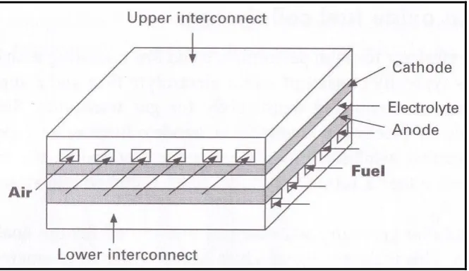
[image:36.595.154.487.153.345.2]and function as interconnects and current collectors simultaneously. Figure 2.3 below shows a schematic of an anode-supported planar SOFC configuration with metal interconnect.
Figure 2.3: Schematic of cell configuration in an anode-supported planar SOFC stack (Huang & Goodenough, 2009)
2.5 Low Temperature Solid Oxide Fuel Cell (LTSOFC)
Previously, the traditional SOFC have to be operated at temperatures above 800˚C in
order to obtain a desirable power density. However, the performance of the electrodes decreases over long time of operation. This was due to the high temperature operation, the components of the fuel cells unavoidably react with each other, affected the stability of the SOFC system and deteriorate the cell performance (Huijsmans et al., 1998, Minh, 2004 & Huang et al., 2011). Moreover, in terms of practical implications especially in domestic and industrial, SOFC have not been realized as it has high material cost, high temperature operation and issues of safety. In addition, high operating temperatures (above 800˚C) of SOFCs can lead to
17
All those fact regarding the disadvantages of high temperature SOFC represents the reasons that high temperature SOFC faces the obstacle to be potentially commercialized. Hence, to overcome the disadvantages of high temperature SOFC, the effort has been done to reduce the operating temperature of SOFC to intermediate temperature (IT) (600-800˚C). However, the intermediate temperature SOFC
(ITSOFC) also creates another problem that the overpotential resistances of the electrodes, especially the cathode, increase rapidly with decreasing the operating temperature. Each of the SOFC components (anode, cathode, and electrolyte) requires different types of materials. As the operating temperature is reduced, the materials as well will change to suit with the temperature while maintaining the performance. Considering the type of material will affect the overall cell performance, hence the materials used also change due to the change in operational temperature.
One of the key improvements in cell performance can be realized by investigating and enhancing novel or as-developed cathode materials (Fu et al., 2007 & Li et al., 2010). SOFC cathode materials must have certain characteristics to help develop and maintain cell performance. Liu et al., (2012) stated that (La, Sr)(Co, Fe)O3 (LSCF) perovskite oxides are widely accepted as the cathode material for SOFC that operate in the intermediate temperature between 600-800˚C due to their
high electronic and ionic conductivities. However, it also comes to the challenge where the electrochemical performance of LSCF cathodes is not stable with time, and the performance degradation becomes one of the issues that limit LSCF applications in SOFC. There are two possible mechanisms for the degradation of LSCF cathodes, that is, the instability of LSCF materials and the change of LSCF microstructure.
Using intermediate-to low-temperature (IT-LTSOFC) requires cathode materials that have good electronic and ionic conductivities at temperatures below 800˚C. Thus, mixed ionic-electronic conductors (MIEC) such as perovskite-based
18
cathode component materials offering higher electronic and ionic conductivity is important. LSCF is a perovskite-based material suitable for IT-LTSOFC applications. A composite cathode is introduced to improve cathodic polarization. Electrolyte materials such as samarium- doped ceria (SDC) and gadolinium-doped ceria (GDC) are mixed with LSCF to enhance the ionic conductivity of the cathode (Zhang et al., 2005 & Huang & Chou, 2009). Composite technology allows the creation of electrodes with higher effective surface area to increase the efficiency of the exchange reactions and consequently to decrease the electrode over potentials (Seabaugh & Swartz, 2009).
Research efforts have been increasingly focusing on the development of intermediate-to-low temperature (400-600˚C) SOFC (Huang et al., 2012). Moreover,
an innovative solid carbonate-oxide composite known as SDC carbonate (SDCC) that performed well at low temperatures of 400–600˚C was discovered (Zhu, 2001 &
Jarot et al., 2011). The combination of LSCF with SDCC is expected to achieve outstanding properties as composite cathode materials for IT–LTSOFC. Moreover, previous researchers also found that the addition of noble metal such Ag, Pt and Pd towards LSCF cathode materials were said able to improve the conductivity of the LTSOFC (Haanappel et al., 2004 & Simner et al., 2006)
2.6 Cathode for LTSOFC
Cathode components of fuel cell construct from porous structure materials to allow the flow of air or oxygen. Here is the region where the oxygen reduction reaction (ORR) to occur. Cathode materials with a porous structure stable at the necessary fabrication and operating conditions are desirable for improving the performance of LTSOFC cathodes. Nowadays research has been design to lower the operation temperature of SOFC so that the fuel cell can operate at temperature below 600˚C
consequently a better and sustain LTSOFC can be commercialize. Despite of having advantage from LTSOFC, lowering the operating temperature decreases the electrode kinetics and results in large interfacial polarization resistances. This effecting most the ORR process at the cathode.
19
reduction must be maintained. Cathode for LTSOFC must be produced using materials that have higher electronic and ionic conductivity to migrate the oxygen (O2) through the triple phase boundary (TPB). TPB is the region where provide the area in which electrode (cathode), air and electrolyte meet each other for electrochemical reaction to occur. In terms of the microstructure, TPB have a great effect on the electrochemical performance of cathode materials.
In having the higher electrochemical performance of cathode for LTSOFC, problems persist in the areas of chemical stability and thermal expansion match with other cell components also need to solve. A trade-off between electrochemical performance and thermal expansion is necessary to identify an optimum cathode performance. Furthermore, long-term stability is a significant factor to be considered for practical LTSOFC system to sustain. Hence, cathode of LTSOFC one of the important components apart from the whole complete system. Cathode for LTSOFC still in process of development and optimization so that it can be commercialize relatively with low cost.
2.6.1 Properties for cathode
In short, in a SOFC system, the fuel is oxidized at an electrochemical interface (electrode called anode), accepting electrons and donating these electrons at a second electrochemical interface (electrode called cathode, separated from the anode) to an oxidant, (oxygen) which is reduced by accepting these electrons (Doeff, 2012). Cathode for SOFC must have certain characteristics in order to play the role as oxygen reduction base in SOFC systems. In general, it must have these characteristics (Singhal, 2000, Wincewiz & Cooper, 2005 & Sun et al., 2010):
High electronic conductivity (preferably over 100 Scm-1 under oxidizing
atmosphere)
Higher ionic conductivity (approximately 10-1 Scm-1)
Chemically compatible with neighboring cell component (usually the
electrolyte)
Thermal expansion coefficient (TEC) compatibility with electrolyte and others SOFC’s components.
20
Catalyze the dissociation of oxygen
Can be made thin and porous (thin enough to avoid mass transfer losses, but
thick enough to provide area and distribute current) Adhesion to electrolyte surface
Suitable porosity range
Large triple phase boundary (TPB)
High catalytic activity for oxygen reduction reaction (ORR) to occur Relatively simple fabrication
Uses relatively inexpensive materials (low cost)
The choice of cathode materials is largely dependent on the electrolyte materials used with care taken to match thermal expansion coefficients and avoid undesirable interface reactions. The materials for cathode can be categorized into two categories, (1) electronic conductivity materials and (2) mixed ionic-electronic conductivity materials. Since the operating temperature of SOFC has been lowered to low operation temperature, the mixed ionic-electronic conductivity materials has gain much attention and preferably used by the researchers. This was due to low operating temperature; the previous and familiar materials used such lanthanum strontium manganite (LSM) has low ionic conductivity and limit the TPB in cathode consequently reduce the overall cathode performance. Therefore, the mixed ionic-electronic conductivity (MIEC) material was introduced such lanthanum strontium cobalt ferrite (LSCF) purposing in enlarge the TPB area and enhance the performance of the SOFC (Fergus et al., 2009 & Sun et al., 2010).
21
well as composite cathode which have meet the characteristic of SOFC’s cathode materials.
Figure 2.4: Schematic diagram of the (a) electrode surface path, (b) the bulk path, and (c) the electrolyte surface path (where O2 – oxygen gas Oad – adsorption oxygen
O2- - oxygen ion) (Sun et al., 2010)
2.6.2 Lanthanum Strontium Cobalt Ferrite (La1-xSrxCo1-yFeyO3-δ) (LSCF)
22
[image:42.595.158.480.157.316.2]of the A-site and B-site cations adds up to less than six, the missing charge is made up by introducing vacancies at the oxygen lattice sites. Figure 2.5 shows the typical structure of the cubic perovskite ABO3. (Sun et al., 2010).
Figure 2.5: Unit cell of the ABO3 perovskite structure (Sun et al., 2010)
Most cathode materials rely on doping of both the A and B sites to improve electrical conductivity and electrocatalytic performance. The ideal structure of perovskite is cubic lattice as shown in Figure 2.5. However, most of oxide perovskite compound crystallize with polymorph structure (rhombohedral, hexagonal or orthorhombic) in which there was a distortion at its perovskite structure (Tai et al., 1995). Sun et al., (2010) also stated that many perovskite structures are distorted and do not have cubic symmetry. Common distortions such as cation displacements within the octahedra and tilting of the octahedra are related to the properties of the A and B substituted atoms.
La0.6Sr0.4Co0.2Fe0.8O3-δ (LSCF6428) will give cubic crystallite perovskite structure when calcined at low temperature in range of 600-800˚C. When calcined at
high temperature (1000˚C), the cubic structure changes to rhombohedral. The
amount of Sr in LSCF6428 also affecting the crystallite structure. LSCF in which containing 0.2 ≤ Sr ≤ 0.4 tends to have rhombohedral structure meanwhile the low range of Sr containing; 0.15 ≤ Sr ≤ 0.2 will gives cubic structure (Waller et al.,
1996). Moreover Waller et al., (1996) also found that the calcinations was the factor affecting the structure of the LSCF perovskite. Based on previous researchers, LSCF was identified as the excellent candidate for cathode materials in IT-LTSOFC applications (Wincewicz & Cooper, 2005 & Ghouse et al., 2010).
Oxygen Anion Kation A
23
There were a lots of XRD studies of these materials have been termed in situ, in which situ means that the XRD patterns were collected at high temperature or in a controlled gas atmosphere. Such in situ XRD studies of LSCF have provided valuable information regarding its thermal and chemical expansion coefficients and phase stability (Hashimoto et al., 2011). Finding in study conducted by Da Côrte, Da Conceicao & Souza (2013), indicates that LSCF aso had rhombohedral structure (space group R3c). The rhombohedral symmetry was also observed by Tai (1995) for La0.8Sr0.2Co1−yFeyO3 samples with 0 ≤ y ≤ 0.7 in which indicates that the crystallite size increases with increasing calcination temperature while the micro-strain decreases.
2.7 LSCF composite cathode for LTSOFC
For the past few decades, solid oxide fuel cells (SOFC) have emerged as one of the new alternative energy resources. It offers high efficiency power generation, clean energy conversion with low emissions and low noise. Because of its high operating temperatures (800-1000˚C), high temperature SOFC (HTSOFC) has facing some problems such as difficulties on construction, material and process selection, thermal expansion mismatch, lower durability and less opportunities to mass product. As the solution, research is conducting to lower the operating temperature of SOFCs aiming to improve their life expectancy and reliability (Jarot et al., 2011). However, the reduction of operating temperature gives the consequences of inefficiency to the cathode elements as the cathode polarization resistance increase which cause substantial performance decline (Fan et al., 2011).
Rahman et al., (2012) reported that designing a high performance electrode with a low polarization resistance such as using a composite cathode potentially able to solve the problems. Recently, the addition of electrolyte material to the cathode material has increased the triple phase (air/electrode/electrolyte) regions where the electrochemical reactions occur. Mixed ionic and electronic conductors such as La0.6Sr0.4Co0.2Fe0.8O3-δ (LSCF) is one of the candidates that has been applied with
24
Based on previous research, electrolyte materials such as samarium-doped ceria (SDC) and gadolinium-doped ceria (GDC) are mixed with LSCF to enhance the ionic conductivity of the cathode (Zhang et al., 2005 & Murray et al., 2002). The higher ionic conductivities of SDC and GDC have made them suitable to be combined with LSCF as they are ionic conductor materials. Moreover, LSCF and cerium electrolyte does not react with each other since they have the same TEC and the problems of thermal mismatch can be avoided. This combination actually will enlarge the area of electrochemical activity and enhance the electrical conductivity of SOFC (Baharuddin et al., 2013).
2.7.1 Electrochemical properties and performance of LSCF composite
cathode
For the past decade, there are many research has been conducted worldwide regarding the development of composite cathode in order to determine the most suitable materials as the cathodes for SOFCs systems. The initial idea to fabricate composite cathode was to obtain more interface region for high ionic conduction pathway. The research work on ceria-based composite in last decade mainly focused on extensive fuel cell performance test based on various ceria-based composite ceramics, such as samarium-doped ceria (SDC) and gadolinium doped ceria (GDC) incorporated with different salts and hydrates, such as chlorides, fluorites and carbonates. Based on these extensive results, it has been approved that ceria-carbonate composite obtained the best performance, which thus became the research highlight of several last decade. This section emphasizes the implementation as well as influence of SDC and GDC ceria electrolyte towards LSCF composite cathode.
2.7.1.1 Influence of SDC ceria-electrolyte