NEW DESIGN OF TUNED VIBRATION ABSORBER FOR WIDE FREQUENCY RANGE APPLICATION
MOHD HAFIZ BIN GHAZALI
A dissertation submitted in partial fulfilment of the
requirement for the award of the degree of
Master of Mechanical Engineering
Faculty of Mechanical Engineering (Manufacturing) Universiti Tun Hussein Onn Malaysia
ABSTRACT
ABSTRAK
TABLE OF CONTENTS
TITLE i
DECLARATION ii
ACKNOWLEDGEMENT iv
ABSTRACT v
ABSTRAK vi
CONTENTS vii
LIST OF TABLES xi
LIST OF FIGURES xii
LIST OF APPENDICES xiv
CHAPTER 1 INTRODUCTION 1
1.1 Background of Study 1
1.2 Problem Statement 3
1.3 Objective 3
1.4 Scope of Study 4
1.5 Significance of Study 4
CHAPTER 2 LITERATURE STUDY 5
2.1 Theory of Vibration 5
2.2 Source of Vibration 6
2.3 Vibration Control Techniques 7
2.4.1 Passive Vibration Absorber 8
2.4.2 Active Vibration Absorber 9
2.4.3 Hybrid Vibration Absorber 11
2.5 Available Vibration Absorber in Market 12
2.5.1 Tuned Mass Damper 12
2.5.2 Stockbridge Damper 13 2.5.3 Bridge Vibration Absorber 14
2.6 Patent Search 15
2.6.1 Patent 1 15
2.6.2 Patent 2 16
2.6.3 Patent 3 18
2.6.4 Patent Description 19
2.7 Previous Study 20
CHAPTER 3 METHODOLOGY 22
3.1 Project Flow Chart 23
3.2 Vibration Absorber 25
3.2.1 Design of Vibration Absorber 25
3.3 Engineering Design Specification 26
3.4 Development of Tuned Vibration Absorber 27
3.5 Material Selection 31
3.5.1 Material Background 31
3.5.2 TVA Weight Estimation 32
3.5.3 Product Costing Analysis 33
3.6 Finite Element Analysis 35
3.6.1 Design 1 Vibration Absorber 35
3.6.2 Design 2 Vibration Absorber 36
3.7.1 Cutting Process 38
3.7.2 Laser Cutting Process 38
3.7.3 Milling Process 39
3.8 Experimental Works 41
3.8.1 List of Instruments 41
3.8.2 Procedure of Using DEWEsoft 44
3.8.3 Experimental Procedure 48
3.9 Sustainable Analysis 50
3.9.1 Design for Disposal & Recyclability Involve 50
3.9.2 Design for Disassembly 51
3.9.3 Life Cycle Assessment (LCA) 51
CHAPTER 4 RESULT AND DISCUSSION 57
4.1 Finite Element Analysis Results 58
4.1.1 Design 1 FE analysis 58
4.1.2 Design 2 FE analysis 61
4.2 Experimental Results 64
4.2.1 Mass Distance ( 0 mm ) 64
4.2.2 Mass Distance ( 10 mm ) 65 4.2.3 Mass Distance ( 20 mm ) 65
4.2.4 Mass Distance ( 30 mm ) 66
4.2.5 Mass Distance ( 40 mm ) 67
CHAPTER 5 CONCLUSION AND RECOMMENDATION 70
5.1 Introduction 70
5.2 Conclusion 70
5.3 Recommendation 71
REFERENCE 73
LIST OF TABLE
2.1 Patent Mechanism Description 19
3.1 Engineering Design Specification 27
3.2 Weight Estimation of the TVA ( Design 1 ) 32 3.3 Weight estimation of the TVA ( Design 2) 33
3.4 Cost Analysis of TVA ( Design 1 ) 34
3.5 Cost Analysis of TVA ( Design 2 ) 34
4.1 Design 1 FE Analysis Result 60
4.2 Design 2 FE Analysis Result 62
4.3 Design 1 experimental result 68
LIST OF FIGURES
2.1 Simple Mass-Spring-Damper Vibration Model 6
2.2 Machine model shows before and after adding a
vibration absorber 8
2.3 Mechanical model with Passive Vibration Absorber 9 2.4 Mechanical model with Active Vibration Absorber 10
2.5 Hybrid vibration absorber structure 11
2.6 Tuned mass damper 12
2.7 View of stockbridge damper 14
2.8 Bridge vibration absorber 15
2.9 Composite Low Rate Spring & Absorber 16
2.10 Vibration absorber unit 17
2.11 Two metal plate positioned while vibrating 17 2.12 Shock Absorber and Auxiliary Spring Unit 18
3.1 Methodology Flow Chart 23
3.2 Design 1 model 25
3.3 Design 2 model 26
3.4 Design 1 overview 28
3.5 Design 2 overview 29
3.6 Design 1 & Design 2 dimension 30
3.7 FE meshed model of design 1 absorber 36
3.8 FE meshed model of design 2 Absorber 36
3.9 Cutting process using automatic band saw machine 38
3.10 Laser cutting process 39
3.11 Milling Process 40
3.12 Completed vibration absorber 40
3.13 Vibration motor shaker & speed controller 41
3.14 Structure with shaker motor 42
3.16 DEWE-201 data analyzer 43
3.17 Accelerometer sensor 43
3.18 Open up DEWEsoft program 44
3.19 Load setup DEWEsoft program 44
3.20 Choose folder on DEWEsoft program 45
3.21 Open selected channel on DEWEsoft program 45
3.22 Accelerometer attached on absorber 46
3.23 Record measurement 46
3.24 Store input data to file 47
3.25 Save data to file 47
3.26 Apparatus setup 48
3.27 Life Cycle Assessment and Sustainability of New Tuned
Vibration Absorber 52
3.28 Sustainability pie chart for carbon footprint 53 3.29 Sustainability pie chart for water eutrophication 54 3.30 Sustainability pie chart for air acidification 55 3.31 Sustainability pie chart for total energy consumed 56
4.1 FE meshed model of design 1 59
4.2 FE analysis result of design 1 59
4.3 Frequency trend of design 1 absorber 60
4.4 FE meshed model of design 2 61
4.5 FE analysis result of design 2 62
4.6 Frequency trend of design 2 absorber 63
4.7 ( 0 mm ) Mass Distance 64
4.8 ( 10 ) mm Mass Distance 65
4.9 ( 20 ) mm Mass Distance 66
4.10 ( 30 ) mm Mass Distance 66
4.11 ( 40 ) mm Mass Distance 67
4.12 Superimposed result 68
LIST OF APPENDICES
Appendix A PS 1 Gantt Chart Appendix B PS 2 Gantt Chart
CHAPTER 1
INTRODUCTION
1.1 Background of Study
Most vibrations are undesirable in machines and structures because they increased stresses, energy losses, cause added wear, increase bearing loads, induce fatigue, create passenger discomfort in vehicles, and absorb energy from the system. Rotating machine parts need careful balancing in order to prevent damage from vibrations.
Uncontrolled vibrations can leave a bad impression to the machine, structure, and human. Vibration on machine can damage the equipment, decrease the machine lifetime and
also causing the safety factor problems. Some examples of failure due to vibration are imbalanced helicopter blades due to high speed spinning can lead to catastrophic failure of the helicopter blades. Other industrial machinery such as pumps, compressors, turbo engine can cause excessive vibration surrounding structures, which cause inefficient operation of the machine and also produces excess noise that can cause human discomfort.
equilibrium state in such a vibration system becomes unstable, and any disturbance causes the perturbations to grow until some effect limits any further growth. In contrast to forced vibrations, the exciting force is independent of the vibrations and can still persist even when the system is prevented from vibrating.
There is a methods use in order to control the vibration. The common approach to mitigate vibration, is by adding absorber to the structure. Passive, active and hybrid vibration absorber is a control methods approach used to absorbing the vibration. Passive control devices is system which does not required speed variations during operation and limited in range and effectiveness while active control is a devices that control dynamic performance and it consists of sensors, actuators and controller. Hybrid control devices is a combination between passive and active control devices and it is more flexible with the frequency range.
1.2 Problem Statement
Vibration control has been and remains an important field of study in engineering. The harmonic vibration of a machine is an undesirable effect of rotating out of balance mass within the system. However the vibration of the machine can be suppressed by attaching vibration absorber whose natural frequency is tuned to be equivalent to the excitation frequency of the machine. Although it was proved to reduce structural vibration significantly, the conventional design of the vibration absorber is only working at one particular forcing frequency. This means that if the forcing frequency beyond the tuning frequency range of absorber, the absorber will not be able to reduce the vibration. On top of that, the conventional design of vibration absorber employed a heavy metal to fabricate, this produce drawback of adding additional weight to the structure. For lightweight structure application, such as aircraft, automotive and submarine, the adding weight will effect on the fuel consumption of vehicle. In fact, due to the large size and heavyweight of conventional absorber, it is not suitable to be carried anywhere easily. A way of overcoming this problem is by designing a tuned vibration absorber (TVA) which can be tuned, light in weight and suitable for mobility purposes.
1.3 Objective
1.4 Scope of Study
The scopes of this project are:
i. To design and fabricate a new tuned vibration absorber.
ii. In prior to fabrication, details structural vibration analysis of the designs is carried out by using SolidWorks®.
iii. The selection criteria of TVA is based on the frequency range, weight, and degree of freedom.
iv. The weight of TVA is not exceeding than 1 kg and can bring anywhere for mobility purposes.
v. The size of TVA in the range of 100mm x 100mm.
vi. The fabricated TVA is be tested in-house laboratory
vii. The TVA is tuned to the first frequency mode of the primary structure and the research study will only be done in the frequency range of 0-1000 Hz.
1.5 Significant of Study
CHAPTER 2
LITERATURE REVIEW
2.1 Theory of Vibration
Vibration is a mechanical phenomenon that happens in a phase of solid, liquid or gas. Virtually, all of available and existing machine have parts which were moving and relocating and this situation can be considered as vibration. The ability of a things or parts to move will cause a vibration phenomenon where an object will turn in the shift from a state of equilibrium. In general, acceleration, velocity and displacement are the common elements related to vibration. Essentially, forces and mass oscillations motion are the main concepts of vibration which means that any mass with elasticity is capable to vibrate [1-4].
Figure 2.1 : Simple Mass-Spring-Damper Vibration Model [5]
2.2 Source of Vibration
Vibration, which is commonly referred to as noise, can be segregated into three main categories which is ground vibrations, acoustic vibrations, and forces applied directly to the load on the working surface. Seismic vibrations include all sources that make the floor under the experimental setup vibrate. Common seismic vibration sources are foot traffic, vehicular traffic, wind blowing the building, and building ventilation fans, to name a few. Many of the sources that generate seismic vibrations also generate acoustic vibrations [6-8].
2.3 Vibration Control Techniques
There is many methods use to control the vibration of a machine. The vibrations can be limit to a level that can be accepted if it is made particularly stiff and massive and the fundamental frequency may be high to limit the vibrations. The cost usually too high for that approach, although many structures and machine built by 19th century had relatively few vibration problems because the massive scale. The structures tend to be as light as can be achieved with the necessarily lowering stiffness even more than the mass is reduced, so the resonance frequencies can emerge where the excitation forces high [9]. It is necessary to calculate such the corresponding modes and the frequencies of vibration and as the response for expected excitation forces and the modern finite element are well suited for this task. In this way, most structure and machines can be designed to behave well in the expected operational environments. The same codes can be and are used to estimate the effect of selected engineering changes, such as changes of metal thickness and other dimensions. The role of good design in creating systems which suffer a minimum of vibration problems cannot be underestimated [10].
2.4 Vibration Absorber
[image:19.595.98.511.371.521.2]Another common solution to protect the device from steady state harmonic disturbance at a constant frequency is by using a vibration absorber. This approach will assist the natural frequency of the system by shifting it away from the excitation frequency in order to the resonance and surpluses vibration does not take place of it [11]. Figure 2.2 indicates a machine model before and after adding vibration absorber. The minimum motion of the original mass influenced on the choosing of the values of the absorber mass and it stiffness. This was attached with substantial motion while added the absorber system as illustrated. Absorbers are frequently used on the machines which run at the constant speed such as sanders, compactors, reciprocating tools and electric razors [12].
Figure 2.2 : Machine model shows before and after adding a vibration absorber [13]
2.4.1 Passive Vibration Absorber
Theoretically, by adding the structural modification, it can produce the passive control that can be thought. Therefore, to improve the vibrational response of the system by chosen α which represents added stiffness then it can be declared that as a passive control procedure. The use of added power or energy can distinguished between passive control and active
control. Generally, the vibration absorber is the most common passive control device and apart from that the other methods of passive control are by adding mass and changing stiffness values [14]. A mass spring subsystem coupled to a superstructure to control its oscillations under the action of periodic excitation is known as a passive vibration absorber. As in Figure 2.3 indicates of a simple form of this arrangement where m1 is a mass emulating the superstructure and K1 is its mounting spring. Hence, The second mass, M2 the coupling spring K2 and a viscous damper d constitute the absorber system. the harmonic base motion with amplitude A and angular frequency was driven the superstructure. After that, let x1 be the displacement of M2 and x2 the displacement of M2 and as thus far the elementary books on linear vibration theory prove that the problem is well known [15].
Figure 2.3 : Mechanical model with Passive Vibration Absorber [16]
2.4.2 Active Vibration Absorber
The vibrating mechanical system as shown in Figure 2.4, which consists of an active undamped dynamic vibration absorber (secondary system) coupled to the perturbed mechanical (primary system). The generalized coordinates are the displacements of both masses, x1 and x2 respectively. The u is represents the force control input and f(t) some harmonic perturbation, possibly unknown. Here m1, k1 and c1 denote mass, linear stiffness and linear viscous damping on the primary system, respectively. Similarly m2, k2 and c2 denote mass, stiffness and viscous damping of the dynamic vibration absorber. When u=0 the active vibration absorber becomes only a passive vibration absorber [18, 19].
2.4.3 Hybrid Vibration Absorber
[image:22.595.69.447.459.712.2]Hybrid vibration technology is a combination of active and passive vibration. This structural control systems come from the natural evolution of passive control technologies and passive energy dissipation. The possible use of active control systems and some combinations of passive and active systems, so called hybrid systems, as a means of structural protection against wind and seismic loads has received considerable attention in recent years. Hybrid control systems are force delivery devices integrated with real-time processing controllers and sensors within the structure [21, 22]. They act simultaneously with the hazardous excitation to provide enhanced structural behavior for improved service and safety. An hybrid structural control system consists a sensors to measure either external excitations, structural response variables, or both. This system also has a devices to process the measured information and able to compute necessary control force needed based on a given control algorithm. The actuators usually powered by external sources, to produce the required forces. Figure 2.5 shows the hybrid vibration absorber structure.
2.5 Available Vibration Absorber in Market
2.5.1 Tuned Mass Dampers
[image:23.595.90.469.470.644.2]Tuned mass dampers (TMD) also known as harmonic absorber are resonant devices used to suppress or absorb vibration. When installed properly on a machine or structure, they draw away vibrational energy from the structure or machine and dissipate it internally, reducing the motion of the machine. Their application can prevent discomfort, damage, or outright structural failure. They are frequently used in power transmission, automobiles and buildings. Tuned mass dampers stabilize against violent motion caused by harmonic vibration [24, 25]. A tuned damper reduces the vibration of a system with a comparatively lightweight component so that the worst-case vibrations are less intense. Figure 2.6 shows the tuned mass dampers that available in the market.
As solutions to vibration problems, the tuned mass dampers (TMD) have a number of
attractive features which is :
They are inherently compact, modular devices that can have a simple interface to the base structure.
They can be added readily to a base structure that is already designed or even built.
Added weight can be kept to a minimum.
The tuned device does not impact the static strength or stiffness of the base structure.
It is often possible to characterize the base structure by inexpensive test or analysis
2.5.2 Stockbridge Damper
A stockbridge damper is a tuned mass damper used to suppress wind-induced vibrations on taut cables, such as overhead power lines. The dumbbell-shaped device consists of two masses at the ends of a short length of cable or flexible rod, which is clamped at its middle to the main cable. The damper is designed to dissipate the energy of oscillations in the main cable to an acceptable level. Its distinctive shape gives it the nickname “dog-bone damper”. In this mechanism, vibrations in the main cable were passed down through the clamp and into the shorter damper. This would flex and cause the symmetrically placed concrete blocks at its ends to oscillate [27, 28]. Modern designs use metal bell-shaped weights rather than stockbridge's concrete blocks. The bell is hollow and the damper cable is fixed
internally to the distal end, which permits relative motion between the cable and damping
weights. To provide for greater freedom of motion, the weights may be partially slotted in the
vertical plane, allowing the cable to travel outside the confines of the bell. In some
Original design Modern Design
Figure 2.7 : View of stockbridge damper [29]
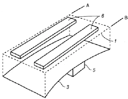
2.5.3 Bridge Vibration Absorber
Figure 2.8 : Bridge vibration absorber [31]
2.6 Patent Search
2.6.1 Patent 1 – Composite Low Rate Spring & Absorber ( US 3,130,964 ) [32]
Figure 2.9 : Composite Low Rate Spring & Absorber
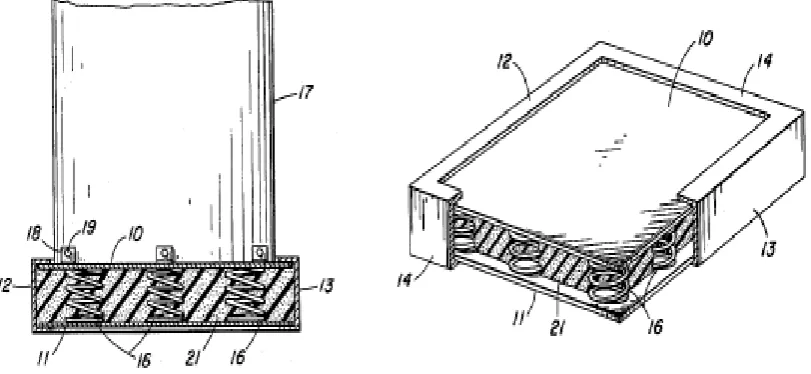
2.6.2 Patent 2 – Selective Tuned Vibration Absorber ( US 6,279,679 B1 ) [33]
Figure 2.10 : Vibration absorber unit
[image:28.595.213.423.422.584.2]2.6.3 Patent 3 – Shock Absorber and Auxiliary Spring Unit ( US 3,263,983 ) [34]
[image:29.595.116.456.368.558.2]This device was invented by Charles V.Bliven and Wayne from United States in 30 Dec 1963. The main purpose of this device is to give car stability, steering control and improve comfort which is isolated from road noise,bumps and vibratios. This device present invention relates to vehicle suspension systems and more particularly to that class of suspension spring. The suspension allows the wheels to move up and down independently from the rest of the car. That will keep the wheels on the road while hit bumps and protect the vehicle from damage and wear. Figure 2.12 shows the hand and power screw-press mechanism.
2.6.4 Patent Description
[image:30.595.84.517.314.592.2]Table 1 describes the function of each patent related in the making of a new tuned vibration absorber. The description including the patent mechanism, the advantages and disadvantages on each concept. There are three patents placed in this study and that is the mechanism related in order to produce the new tuned vibration absorber. In addition, the description of these patent is al be a reference to developing a tuned vibration absorber.
Table 2.1 : Patent mechanism description
Patent Patent 1 Patent 2 Patent 3
Title Composite Low Rate Spring &
Absorber
Selective Tuned Vibration Absorber
Shock Absorber and Auxiliary Spring Unit
Mechanism This device use shock absorbers mechanism and in particular to shock
pads
This device use damping plates method to absorb the
vibration.
This device use spring mechanism to
absorb vibration
Advantages No need a power supply
No need a power supply
Available everywhere
Disadvantages Limited to certain load weight
The product is big and require a lot of
space
2.7 Previous Study
In this thesis, the important literature review has been carried out. Some of the literature review that had been studied are shown below:
A study of tuned mass dampers and vibration absorbers has been carried out by R. Kashani [35]. He investigated the interaction of tuned mass dampers with a structure by analyzed the vibration of a cantilever beam equipped with one tuned mass damper. The tuned mass damper was appended to the tip of the beam and used disturbance force to excite the beam at the tip. The first natural frequency of the beam was around 6Hz with 40% damping ratio. From the figure obtained from test, the frequency response function (FRF) of the cantilever beam without tuned mass damper recorded 20dB (magnitude), as the highest peak. After equipped with a tuned mass damper, the magnitude reduced to 7dB. Meanwhile, for vibration absorbers he did a study about vibration cancelation aspect of this device by appended a vibration absorber to one degree of freedom system. The flexible structure was subjected with disturbance force also. The result stated that by adding the vibration absorber to the original one degree of freedom system, it changed to a two degree of freedom system.
CHAPTER 3
METHODOLOGY
This chapter will discuss about the steps to design and develop the tuned vibration absorber. Methodology is important work scope to conduct a project and make the process to implement in this research done in a proper way. The right sequences of the steps or procedures will lead us to run the project with more easier and smoother. All the procedure to accomplish this research are well explained in this chapter. There are some equipment that effect on this research need to be considered such as specification, stiffness, mass of the absorber and damping ratio. The equipment that use for this research need to be prepared in term of design, fabrication process and experimental as well.
3.1 Methodology Flow Chart
Figure 3.1: Methodology Flow Chart Literature review on previous study
Design the absorber Begin
End Data Analysis
& discussion Fabricate the
design
Experimental approach ( Vibration test) Simulation
approach (FEA)
Measured performance of
TVA Material selection and
analysis
As shown in Figure 3.1, during the literature review on previous study phase, all the information about previous study are collected such as related mechanism, patent search, available product and researchers study. Thereafter, the design concept is further developed by drawing through computer aided design (CAD) 3D modelling software by using SolidWorks®. The proposed software is then simulated in CAD software to determine the design workability. Futhermore the suitable material are selected for every component of the vibration absorber component with recommendation of manufacturing process and analyzing.
After the design process is completed, the author proceed to the fabrication phase. In this phase, the components on the prototype are fabricated using the dimension and material selection that had been determined earlier in the project. Then , the projects will undergoing simulation approach by using finite element method. After it finish, the projects will go to experimental phase which is vibration test take place. The project undergoes several of testing to ensure that it passed the minimum requirement that author had determined in the design process. All these experiment are done several times to get the average result. The result gained been analysed and go through validation process.
REFERENCE
1. S. S. Rao, Mechanical vibrations. Prentica Hall, fourth ed., 2005. 2. W. J. Palm III, Mechanical vibration. John Wiley & Sons, 2007.
3. M. M. Boyadjis, “Solving structural vibration problems using deflection shape and finite element analysis,” Turbomachinery analysis, pp. 85–102, 2009.
4. D. J. Inman, Engineering Vibration. Prentice Hall, Inc., 1996.
5. http://blogs.mathworks.com/loren/2013/10/15/function-is-as-functiontests/
6. Scan M. DeCamillo, “Journal bearing vibration ans SSV hash”, thirty-seventh Turbomachinery symposium, 2008.
7. Vibration And Noise Control Lab pdf, “Active And Passive Control Of Vibration And Noise”, University of Maryland.
8. Andrew D. Dimarogonas, Sam Haddad (1992), “Vibration For Engineers”, Prentice Hall, Englewood Cliffs, New Jersey.
9. Dr. R.E. Kielb, Dr.H.P Gavin, C.J Dillenbeck (2005), “Tuned Vibration Absorbers: Analysis, Visualization, Experimentation, and Design”, Thesis of Pratt School Of Engineering, Duke University, Durham.
10. D. I. G. Jones, Viscoelastic Vibration Damping. John Wiley and sons, 2001. 11. M. R. Mainal and M. Y. Abdullah, Penggunaan Mekanik Getaran. Penerbitan
Akademik, UTM., 1993.
12. M. A. Wahab, Dynamics and Vibration. John Wiley and Sons, 2008. 13. http://engineeronadisk.com/V3/engineeronadisk-125.html
14. D. J. Inman, Engineering Vibration. Prentice Hall, Inc., 1996.
15. D. J. Inman, Vibration with Control, Measurement and Stability. Prentice Hall, Inc., 1989.
16. http://www.usq.edu.au/course/material/mec3403/vibration-2/vibration-2.htm 17. A. Hartung, H. Schmieg, and P. Vielsack, “Passive vibration absorber with dry
friction,” Archieved of Applied Mechanics, vol. 71, pp. 463–472, 2001.
18. B. Carbal, Silva-Navarro, and S. R. H., “Active vibration absorbers,” Proceedings of the international Control Conference, vol. 13, pp. 791–796, 2003.
20. http://iopscience.iop.org/0964-1726/23/2/025032
21. Wu, Shang-Teh, Yea-Ying Chiu, and Yuan-Chih Yeh. "Hybrid vibration absorber with virtual passive devices." Journal of sound and vibration 299.1 (2007): 247-260.
22. Utsumi, Masahiko. "Active stabilization of a hybrid vibration absorber subjected to velocity feedback control." AIAA journal 45.4 (2007): 786-792.
23. https://s3101959.wordpress.com/2012/03/18/fundamentals-of-automobile-design/ 24. Kaynia, Amir M., John M. Biggs, and Daniele Veneziano. "Seismic effectiveness of
tuned mass dampers." Journal of the Structural Division 107.8 (1981): 1465-1484.
25. Kwok, K. C. S., and B. Samali. "Performance of tuned mass dampers under wind loads." Engineering Structures 17.9 (1995): 655-667.
26. http://www.moog.com/products/vibration-suppression-control/
27. Diana, Giorgio, et al. "Stockbridge-type damper effectiveness evaluation. I. Comparison between tests on span and on the shaker." Power Delivery, IEEE
Transactions on 18.4 (2003): 1462-1469.
28. Wagner, H., et al. "Dynamics of Stockbridge dampers." Journal of sound and
Vibration 30.2 (1973): 207-IN2.
29. http://dynamicsystems.asmedigitalcollection.asme.org/article.aspx?articleid=2089740 30. Patten, William N., Ronald L. Sack, and Qiwei He. "Controlled semiactive hydraulic
vibration absorber for bridges." Journal of Structural Engineering122.2 (1996):
187-192.
31. http://www.teratec.ca/category.aspx?catid=11520
32. F.W. JOHNSON, Composite Low Rate Spring and Shock Absorber, 3,130,964 USA Patent Search.
33. Leonard N. Thomasen, Selectively Tuned Vibration Absorber, 6,279,679 B1 USA Patent Search.
34. Charles V.Bliven and Wayne, Shock Absorber and Auxiliary Spring Unit, 3,263,983 USA Patent Search.
35. R. Kashani, “ Tuned Mass Dampers and Vibration Absorbers” DEICON: Ph.D Thesis.
36. Muhammad Mohamed Salleh (2015), “Finite Element Modelling Of Fixed-Fixed End Plate Attached With Vibration Absorber” Thesis Of The University Tun Hussein Onn Malaysia.
![Figure 2.1 : Simple Mass-Spring-Damper Vibration Model [5]](https://thumb-us.123doks.com/thumbv2/123dok_us/8763180.895014/17.595.182.391.79.211/figure-simple-mass-spring-damper-vibration-model.webp)
![Figure 2.2 : Machine model shows before and after adding a vibration absorber [13]](https://thumb-us.123doks.com/thumbv2/123dok_us/8763180.895014/19.595.98.511.371.521/figure-machine-model-shows-adding-vibration-absorber.webp)
![Figure 2.3 : Mechanical model with Passive Vibration Absorber [16]](https://thumb-us.123doks.com/thumbv2/123dok_us/8763180.895014/20.595.104.446.338.435/figure-mechanical-model-passive-vibration-absorber.webp)
![Figure 2.4 : Mechanical model with Active Vibration Absorber [20]](https://thumb-us.123doks.com/thumbv2/123dok_us/8763180.895014/21.595.138.389.289.571/figure-mechanical-model-active-vibration-absorber.webp)
![Figure 2.5 : Hybrid vibration absorber structure [23]](https://thumb-us.123doks.com/thumbv2/123dok_us/8763180.895014/22.595.69.447.459.712/figure-hybrid-vibration-absorber-structure.webp)
![Figure 2.6 : Tuned mass dampers [26]](https://thumb-us.123doks.com/thumbv2/123dok_us/8763180.895014/23.595.90.469.470.644/figure-tuned-mass-dampers.webp)
![Figure 2.7 : View of stockbridge damper [29]](https://thumb-us.123doks.com/thumbv2/123dok_us/8763180.895014/25.595.253.512.121.285/figure-view-stockbridge-damper.webp)
![Figure 2.8 : Bridge vibration absorber [31]](https://thumb-us.123doks.com/thumbv2/123dok_us/8763180.895014/26.595.93.456.86.252/figure-bridge-vibration-absorber.webp)