MODELING AND CONTROL OF 6-DOF OF INDUSTRIAL ROBOT BY USING NEURO-FUZZY CONTROLLER
SYABAN BIN SHAMSULKAMAR
A Project Report submitted in partial fulfillment of the requirement for the award of the
Degree of Master of Electrical Engineering
Faculty of Electrical and Electronic Engineering Universiti Tun Hussein Onn Malaysia
ABSTRACT
ABSTRAK
Penjejak trajektori yang berketepatan tinggi merupakan satu topik yang mencabar dalam kawalan robot industri. Ini adalah disebabkan oleh ketaklelurusan dan gandingan masukan yang wujud di dalam dinamik lengan robot. Laporan projek ini membincangkan mengenai masalah dalam permodelan dan kawalan lengan robot yang mempunyai 6 darjah kebebasan. Kajian ini melibatkan lima peringkat seperti berikut; Pertama, pembangunan model computer-aided design (CAD) 6 DOF lengan robots yang lengkap. Di peringkat kedua, model CAD akan diubah ke model fizikal menggunakan
SimMechanics Link. Kemudian, kawalan Neuro-Fuzzy diguna pakai dalam lengan robot ini. Peringkat kelima adalah membuat penyelakuan. Simulasi atau penyelakuan ini dijalankan menggunakan komputer digital dengan bantuan perisisan MATLAB/SIMULINK. Akhir sekali, keupayaan di antara kawalan Neuro-Fuzzy
CONTENTS
TITLE i
DECLARATION ii
DEDICATION iii
ACKNOWLEDGEMENT iv
ABSTRACT v
ABSTRAK vi
CONTENTS vii
LIST OF TABLES ix
LIST OF FIGURES x
LIST OF ABBREVIATIONS xii
CHAPTER 1 INTRODUCTION 1
1.1 Research Background 1
1.2 Problem Statement 2
1.3 Aims and Objectives 2
1.5 Project Report Outline 3
1.6 Project Planning 4
CHAPTER 2 BRIEF REVIEW 5
2.1 CAD Model 5
2.2 Neuro-Fuzzy Controller 6
2.3 6-DOF Industrial Robot 7
CHAPTER 3 METHODOLOGY 8
3.1 Flow Chart 8
3.2 CAD Model Design 10
3.3 Neuro-Fuzzy Controller Development 11
CHAPTER 4 RESULT AND ANALYSIS 14
4.1 CAD Model Assemblies 14
4.2 Physical Model 15
4.3 Neuro-Fuzzy Controller 16
4.4 Simulation and Comparison 25
4.5 Data Comparison 33
CHAPTER 5 CONCLUSION AND FUTURE WORKS 35
5.1 Conclusion 35
5.2 Suggestion of Future Work 36
REFERENCES 37
LIST OF TABLES
1.1 Research Gant Chart 4
4.1 Data Comparison for ANFIS and PID Controller. 34
LIST OF FIGURES
3.1 Project’s Flow Chart 9
3.2 Assemblies’ Window of SolidWorks 10
3.3 Import Physical Modelling 11
3.4 ANFIS Equivalent Structure 12
3.5 Training Data’s Window for FIS Training 13
4.1 6-DOF of Industrial Robot Arm in Solidworks 14
4.2 6-DOF of Industrial Robot Arm in Matlab 15
4.3 Simulink Block Diagram 16
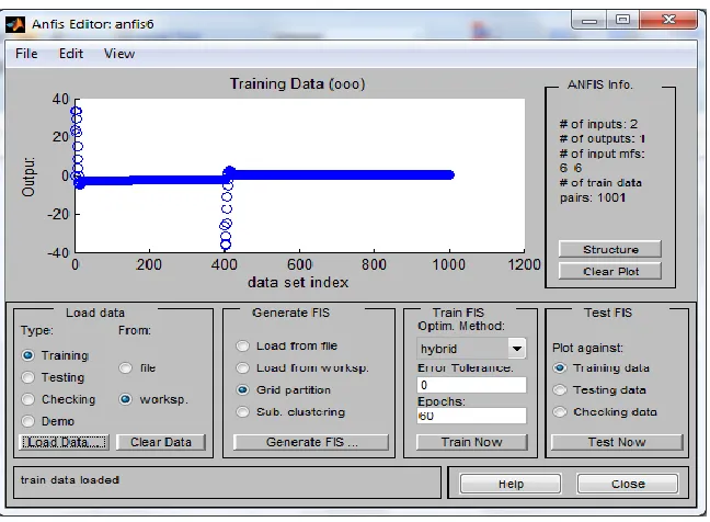
4.4 Training Data Set 17
4.5 FIS Generate 17
4.6 Training Error 18
4.7 FIS Test 19
4.8 ANFIS Model Structure 20
4.9 ANFIS Rules Viewer 21
4.10 ANFIS Rules 22
4.11 MF for Input One 23
4.13 MF for Output 25
4.14 ANFIS Controller and PID Controller for Joint 1 26
4.15 ANFIS Controller and PID Controller for Joint 2 26
4.16 ANFIS Controller and PID Controller for Joint 3 27
4.17 ANFIS Controller and PID Controller for Joint 4 27
4.18 ANFIS Controller and PID Controller for Joint 5 27
4.19 ANFIS Controller and PID Controller for Joint 6 28
4.20 Angle against Time for Joint 1 28
4.21 Angle against Time for Joint 2 29
4.22 Angle against Time for Joint 3 29
4.23 Angle against Time for Joint 4 30
4.24 Angle against Time for Joint 5 30
4.25 Angle against Time for Joint 6 31
4.26 Angle against Time for Joint 1 with Disturbance 31
4.27 Coordinate Frames in Origin Position 32
LIST OF ABBREVIATIONS
3D Three Dimensions
ANFIS Adaptive Neural-Fuzzy Inference System
CAD Computer-Aided Design
DOF Degree of Freedom
FIS Fuzzy Inference System
MF Membership Function
PID Proportional, Integral and Derivative
XML Extensible Markup Language
CHAPTER 1
INTRODUCTION
1.1 Research Background
The wider application of automatic control has developed rapidly in recent years. The reason for this is the complexity of modem plant and the constraints imposed by the increasing demand for higher quality products. Hence the design of a controller which possesses learning capability becomes highly desirable. Robots are highly reliable, dependable and technologically advanced factory equipment. All industrial robots have two physically separate basic elements which are the manipulator arm and the controller (JafarTavoosi et al., 2011).
Nowadays, robots are used in applications that require precise techniques such as in surgical operations. To achieve this target, high precision robots need to be employed and modern controller such as intelligent controller is frequently used. Yusuf SAHIN et al., (2010) used Neuro-Fuzzy controller for 3-DOF SCARA Robot, they used three adaptive networks based fuzzy logic controllers for the control strategy as Neuro-Fuzzy controllers but the third controller for wrist of robot was ineffective to track the desired circular tool trajectory. These controllers were designed by training and checking the data sets obtained from PID control of SCARA robot. In this paper, Neuro-Fuzzy controller will be used for thecontrol of 6-DOF robot arm CAD model.
1.2 Problem Statement
The problem statements of this project are as follow:
i. Robot is a complex system. The modeling in mathematical form shows a higher order and long equations need to be derived. Therefore another approach can be used by using CAD model.
ii. Linear controller needs to be linearized before use in robot system, furthermore the uncertainties of parameters does not included in the controller. Non-linear controller will be used to counter this problem.
iii. Transient response and steady-state response of non-linear controller can be improved by using the hybrid controller of two non-linear controllers which are thefuzzy and neural-network controller.
1.3 Aims and Objectives
arm joint with high stability and efficiency. To achieve these aims, the objectives of this research are formulated as follow:
i. To design a robot arm model based on CAD model.
ii. To develop a Neuro-Fuzzy controller for the robot arm system.
iii. To evaluate the proposed controller performance through simulation study. iv. To compare the proposed controller performance with conventional controller.
1.4 Scope of Project
This model and controller is mainly for six (6) degree of freedom of industrial robots by using CAD design. Controller development will be based on Artificial Intelligence such as Neuro-Fuzzy controller. Matlab/Simulink and SolidWorks will be used as simulation platform.
1.5 Project Report Outline
This thesis consists of five chapters. Chapter 2 deals with the brief review of the CAD model of robot arm. Then Neuro-Fuzzy controller will be presented from previous journal and finally a brief review of the 6-DOF industrial robot arm.
Chapter 3 presents the methodology that shows the steps taken in completing the project in the forms of flow charts. , CAD model design and Neuro Fuzzy controller development are going to be presented in this chapter.
Chapter 5 summarizes the work undertaken. Recommendations for future work of this project are presented at the end of the chapter.
1.6 Project Planning
[image:13.612.110.548.262.714.2]The Research Gantt Chart for this project can be summarized as in Table 1.1.
Table 1.1 Research GanttChart
Month Task
M1 M2 M3 M4 M5 M6 M7 M8 M9 M10 M11 M12
1 Literature Review
2 CAD Model Development
3 Sim-Mechanics Simulink
4 Controller Design
5 Simulation Study
6 Comparison between Controller
7
Preparing Proceeding Paper and Journal
CHAPTER 2
BRIEF REVIEW
2.1 CAD Model
Computer-aided design (CAD) is the use of computer systems to assist in the creation, modification, analysis, or optimization of a design. CAD software is used to increase the productivity of the designer, improve the quality of design, improve communications through documentation, and to create a database for manufacturing.
2.2 Neuro-Fuzzy Controller
Srinivasan Alavandar et al., (2008) used ANFIS to Inverse Kinematics Solution of 3 DOF Planar Robot. In this paper, they illustrated that the ANFIS was able to identify and control of the 2-DOF and 3-DOF robot manipulator and trained ANFIS can be utilized to provide fast and acceptable solutions of the inverse kinematics of robots.
Ouamri Bachir et al., (2012) introduced an Adaptive Neuro-Fuzzy Inference System (ANFIS) based Computed Torque (PD) controller that were applied to the dynamic model of puma 600 robot arm presented. In this article they showed that the ANFIS controller is better compared to fuzzy controller in robustness (adjustment of the rate of variations of the PD gains) and in tracking precision and stability.
Neuro-fuzzy controller can basically learn any static input-output characteristics if the training data is available. This means that the learning algorithm can produce a neuro-fuzzy controller which can copy the control surface of an existing controller if the input-output data from the controller is known, as discussed by Gurpreet S. Sandhu et al., (1997).
2.3 6-DOF Industrial Robot
An industrial robot is defined by (ISO Standard 8373:1994, Manipulating Industrial Robots – Vocabulary) as an automatically controlled, reprogrammable, multipurpose manipulator programmable in three or more axes. The field of robotics may be more practically defined as the study, design and use of robot systems for manufacturing (a top-level definition relying on the prior definition of robot).
CHAPTER 3
METHODOLOGY
3.1 Flow Chart
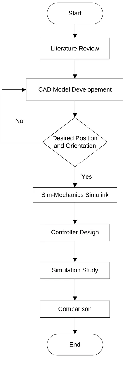
The steps in flow chart for completing this project are shown in Figure 3.1 and the explanations of each step are as follow:
i. Begin with literature review to study previous paper and come up with problem statement.
ii. Secondly, design the CAD model until the desired position and orientation are achieved.
iii. Then the CAD model is converted to physical model by using Sim-Mechanics Simulink.
iv. In the fourth stage, Neuro Fuzzy controller is developed. v. Next, observation of result is done through simulation study
Start
CAD Model Developement
Sim-Mechanics Simulink
Controller Design
Simulation Study
Comparison
End Desired Position
and Orientation
Yes No
[image:18.612.229.428.68.659.2]Literature Review
3.2 CAD Model Design
The CAD model is design by using SolidWorks, the assemblies’ window of SolidWorks
[image:19.612.128.529.205.446.2]can be referred to Figure 3.2. The purpose of creating CAD model in assemblies’ window is to make sure the position and orientation of each part is correct.
Figure 3.2 Assemblies’ Window of SolidWorks
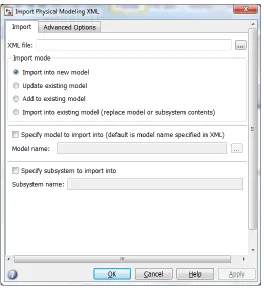
Figure 3.3 Import Physical Modeling
3.3 Neuro Fuzzy Controller Development
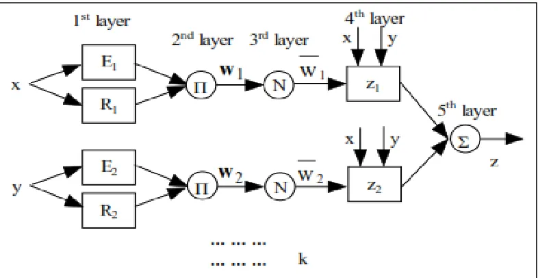
Figure 3.4 ANFIS Equivalent Structure
A network-type structure similar to that of a neural network, which maps inputs through input membership functions and associated parameters, and then through output membership functions and associated parameters to outputs, can be used to interpret the input/output map.
The parameters associated with the membership functions changes through the learning process. The computation of these parameters (or their adjustment) is facilitated by a gradient vector. This gradient vector provides a measure of how well the fuzzy inference system is modeling the input/output data for a given set of parameters. When the gradient vector is obtained, any of several optimization routines can be applied in order to adjust the parameters to reduce some error measure. This error measure is usually defined by the sum of the squared difference between actual and desired outputs. anfis uses either back propagation or a combination of least squares estimation and backpropagation for membership function parameter estimation.
Figure 3.5 Training Data’s Window for FIS Training
Then the FIS file will be generated depending on how many Membership Function (MF) and type of MF. Next the FIS is trained with number of epoch and training error can be seen. Finally the trained FIS will be tested against the training data that contains desired input/output data of the system to be modeled.
Model validation is the process by which the input vectors from input/output data sets on which the FIS was not trained, are presented to the trained FIS model, to see how well the FIS model predicts the corresponding data set output values.
CHAPTER 4
RESULT AND ANALYSIS
4.1 CAD Model Assemblies
[image:23.612.150.508.462.688.2]Figure 4.1 shows the isometric angle for 6-DOF of industrial robot arm, the design has been done by using SolidWorks software.
Figure 4.1 6-DOF of Industrial Robot Arm in Solidworks
Link 2
Link 1
Link 3
Link 4
Link 5
4.2 Physical Model
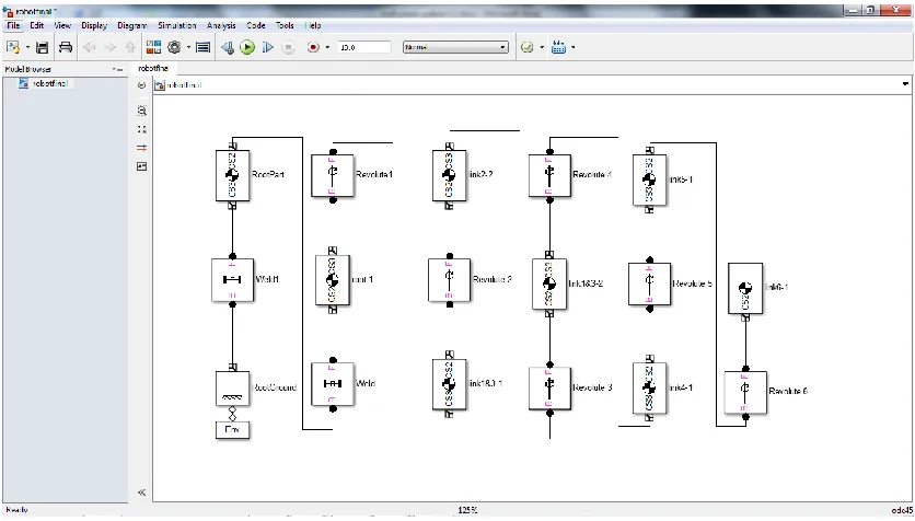
[image:24.612.158.497.181.506.2]Figure 4.2 shows the isometric angle for 6-DOF of industrial robot arm that was converted and imported to Matlab/Simulink file by using SimMechanics Link.
Figure 4.2 6-DOF of Industrial Robot Arm in Matlab/Simulink
Figure 4.3 Simulink Block Diagram
4.3 Neuro-Fuzzy Controller
Figure 4.4 Training Data Set
[image:26.612.194.461.400.673.2]Figure 4.5 show FIS generating where the number of MF for first input (error) and second input (change of error) is 6 and MF type is trimf and constant.
Figure 4.6 shows the training error for 60 epochs where the error is 0.35243 compared to training data.
Figure 4.6 Training Error
Figure 4.7 FIS Test
Figure 4.8 ANFIS Model Structure
Figure 4.10 shows the rules for ANFIS controller with two inputs and one output.
Figure 4.10 ANFIS Rules
Figure 4.11 MF for Input One
Figure 4.12 MF for Input Two
REFERENCES
1. JafarTavoosi, Majid Alaei, and BehrouzJahani (2011), Neuro – Fuzzy Controller for Position Control of Robot Arm. The 5th Symposium on Advances in Science & Technology (SASTech), Iran.
2. Alavandar. S and Nigam. M.J (2008), Adaptive Neuro-Fuzzy Inference System Based Control of Six DOF Robot Manipulator. Journal of Engineering Science and Technology Review 1 (2008) 106-111.
3. Tingjun WANG, Shenshun HU, Jun XU, Dewei YAN and Jiawen BI, Simulation design and application of music playing robot based on SolidWorks, IEEE Measuring Technology and Mechatronics Automation, 2009.
4. Yusuf SAHIN, Mustafa TIKIR, and Arif ANKARALI (2010), Neuro-Fuzzy Trajectory Control of A SCARA Robot. The 2nd International Conference on Computer and Automation Engineering (ICCAE), pages: 298- 302.
5. Hee-Chan Song, Byeong-Sang Kim, and Jae-Bok Song (2012), Tool Path Generation based on Matching between Teaching Points and CAD Model for
Robotic Deburring. The 2012 IEEE/ASME International Conference on Advanced Intelligent Mechatronics, Taiwan.
6. Rosidah Sam, KamarulArrifin, and NorlidaBuniyamin (2012), Simulation of Pick and Place Robotics System Using SolidworksSoftmotion. 2012 International Conference on System Engineering and Technology, Indonesia
8. OuamriBachir and Ahmed-foitihZoubir (2012), Adaptive Neuro-fuzzy Inference System Based Control Of Puma 600 Robot Manipulator. International Journal of Electrical and Computer Engineering (IJECE) Vol.2, No.1, 2012, pp.90-97, ISSN: 2088-8708
9. ISO Standard 8373:1994, Manipulating Industrial Robots – Vocabulary
10.Gohiya, C.S., Sadistap, S.S., Akbar, S.A., Botre, B.A., Design and Development of Digital PID Controller for DC Motor Drive System Using Embedded Platform for
Mobile Robot. Advance Computing Conference (IACC), 2013 IEEE 3rd International.
11.Arulmozhiyal, R.; Kandiban, R (2012).Design of Fuzzy PID controller for Brushless DC motor. Computer Communication and Informatics (ICCCI), 2012 International Conference on Digital Object Identifier: 10.1109/ICCCI.2012.6158919 Publication Year: 2012 , Page(s): 1 - 7