EXPERIMENTAL AND SIMULATION STUDY ON THE EFFECT OF GEOMETRICAL AND FLOW PARAMETERS FOR COMBINED-HOLE FILM
COOLING
HASWIRA BIN HASSAN
A project report submitted in
fulfillment of the requirement for the award of the Degree of Master of Mechanical Engineering
Faculty of Mechanical and Manufacturing Engineering Universiti Tun Hussein Onn Malaysia
ACKNOWLEDGEMENT
I am grateful to the Allah Almighty God for establishing and giving me strength to complete this Master Project. I also like to express my deepest appreciation and sincere thanks to my parents; Hassan bin Jais and Masritah bte Abdullah for their unceasing encouragement and support. A special and sincere gratitude I give to my supervisor, Dr. Mohammad Kamil bin Abdullah whose helped me with valuable guidance and advice in completing this Master Project. His continuing and support throughout this research is greatly appreciated.
I take this opportunity to record my sincere thanks to my research friends; Mohd Hazim Fadli bin Aminnuddin and Ahmad Fuad bin Mohd Noor, who kindly share knowledge, give me support and lend their hand for this Master Project. Last but not least, many thanks go to all laboratory technicians whose guide and teach me during the simulation and experimental study.
ABSTRACT
ABSTRAK
CONTENTS
TITLE i
DECLARATION ii
DEDICATION iii
ACKNOWLEDGEMENT iv
ABSTRACT v
ABSTRAK vi
CONTENTS vii
LIST OF TABLES x
LIST OF FIGURES xi
LIST OF SYMBOLS xvi
LIST OF APPENDICES xvii
CHAPTER 1 INTRODUCTION 1
1.1 Introduction 1
1.2 Background of study 4
1.3 Problem statement 6
1.4 Important of study 7
1.5 Objective of study 7
CHAPTER 2 LITERATURE REVIEW 9
2.1 Introduction 9
2.2 Geometrical effect on the film cooling method 9
2.2.1 Film cooling hole design 10
2.2.2 Length and inclination angle of film
cooling hole 12
2.2.3 Streamwise angle for film cooling hole 14 2.3 Flow setting effect on the film cooling method 15 2.4 Lift-off phenomena of the cooling air in the
cylindrical film cooling hole 17
2.5 Combined-hole film cooling method with
compound angle 18
2.6 Aerodynamic performance of film cooling 23 2.7 Thermal performance of film cooling 25
CHAPTER 3 METHODOLOGY 29
3.1 Introduction 29
3.2 Flow chart 29
3.3 Experimental setup in the present study 32 3.3.1 Main source of the mainstream air 33 3.4.2 Main source of the cooling air
3.4.3 Experimental procedure 3.4 Simulation setup in the present study
3.4.2 Boundary conditions and flow parameters 3.4.3 Performance indicator applied
3.4.4 Mesh dependency test
CHAPTER 4 RESULTS AND DISCUSSION 52
4.1 Introduction 52
4.2 CFD results validation 52
4.3 Effects of lateral distance between two holes, PoD 55 4.4 Effects of streamwise distance between two holes,
LoD 68
4.5 Effects of compound angle, 1 / 2 of combined-hole
film cooling 80
4.6 Total pressure loss coefficient, Cp 89 4.7 Area average film cooling effectiveness 91
CHAPTER 5 CONCLUSION AND RECOMMENDATION 96
5.1 Conclusion 96
5.2 Recommendation 98
REFERENCES 99
LIST OF TABLES
3.1 Flow setting applied in the experimental approach 39 3.2 List of all computational domain at different PoD,
LoD and
42
3.3 List of all computational domain names at different geometrical parameters
44
3.4 Flow setting applied in three different blowing ratios
48
3.5 Elements and nodes details in different type of mesh
LIST OF FIGURES
1.1 Modern gas turbine [1] 1
1.2 T-s and P-ν diagram for Brayton cycle [2] 2
1.3 Turbine inlet temperature of MHI gas turbines series [3]
3
1.4(a) Turbine blade with external cooling techniques [4] 5 1.4(b) Turbine blade with internal cooling techniques [4] 5 2.1(a) Geometry of cylindrical film cooling hole design [22] 11 2.1(b) Geometry of laidback cylindrical film cooling hole
design [22]
11
2.1(c) Geometry of fan-shaped film cooling hole design [7] 11 2.1(d) Geometry of laidback fan-shaped film cooling hole
design [7]
11
2.2(a) Flow streamlines model for counter flow [25] 14 2.2(b) Flow streamlines model for short hole with
unrestricted plenum [25]
14
2.2(c) Flow streamlines model for co-flow [25] 14
2.2(d) Flow streamlines model for long hole with unrestricted plenum [25]
14
2.3(a) Cylindrical film cooling hole with streamwise angle, α [6, 26-30]
15
2.3(b) Fan-shaped film cooling hole with streamwise angle, α [6, 26-30]
15
2.4 The kidney vortex formation of single cylindrical film cooling hole [35]
18
2.5 The kidney vortex formation of combined-hole film cooling with opposite compound angle [37]
20
2.7(a) Combined-hole configurations by Kusterer et al. [38] 21 2.7(b) Combined-hole configurations by Wright et al. [39] 21 2.8 Film cooling arrangement in Javadi et al. [42] 22 2.9 Total pressure loss coefficient contour at x/D = 8 for
low blowing ratio [43]
24
2.10 Total pressure loss coefficient graph at x/D = 8 for different streamwise angle [43]
24
2.11 Pitchwise distributions of total pressure loss coefficient at different blowing ratios [44]
25
2.12 Film cooling effectiveness distributions from the experimental study of Mayhew et al. [45]
26
2.13 Centreline film cooling effectiveness comparison at low blowing ratio, M = 0.5 [45]
26
2.14 Film cooling effectiveness distributions for different film cooling hole design at high blowing ratio [16]
27
2.15 Laterally averaged film cooling effectiveness results at high blowing ratio of Wright et al. [39]
28
3.1 Flow chart involving experimental and simulation approaches
31
3.2 Overall view of the experimental setup 32
3.3 Schematic diagram of the experimental setup 33
3.4 Open loop low speed win tunnel details 34
3.5 Dimensions of the modified test section 34
3.6 Pitot tube used in the experimental approach 35
3.7 Overall view of the blower 36
3.8 Specification of the blower’s motor 36
3.9 Air heater stored in the Bakelite box container 37 3.10 Venturi meter applied to measure the flow rate of the
cooling air
37
3.11 Dimensions on the test plate 38
3.12 Air flow meter used to measure the velocity of the mainstream air
3.13 Two way valve used to turn the cooling air flow inside the plenum
40
3.14 Different value of PoD, LoD and applied in the simulation approach
42
3.15 Detail of computational domain name for different cases
43
3.16 The example of computational domain considered in the simulation approach
44
3.17 Dimensions on the side view of the computational domain
45
3.18 Dimensions on the top view of the computational domain
45
3.19 Hybrid meshing applied on the computational domain in the simulation approach
46
3.20 Structured meshing applied on the critical region of the computational domain
46
3.21 Boundary conditions applied on the computational domain
47
3.22 Mesh dependency test result 51
4.1 Lateral average film cooling effectiveness comparison at M = 0.5
53
4.2 Lateral average film cooling effectiveness comparison at M = 1.0
54
4.3 Lateral average film cooling effectiveness comparison at M = 1.5
55
4.4 Film cooling effectiveness distribution at different PoD for M = 0.5
56
4.5 Lateral average film cooling effectiveness at different PoD for M = 0.5
57
4.6 Vorticity and film cooling effectiveness for AY4545 case at M = 0.5
58
4.7 Vorticity and film cooling effectiveness for BY4545 case at M = 0.5
4.8 Vorticity and film cooling effectiveness for CY4545 case at M = 0.5
60
4.9 Film cooling effectiveness distribution at different PoD for M = 1.0
61
4.10 Lateral average film cooling effectiveness at different PoD for M = 1.0
63
4.11 Film cooling effectiveness distribution at different PoD for M = 1.5
64
4.12 Lateral average film cooling effectiveness at different PoD for M = 1.5
65
4.13 Isosurface of film cooling effectiveness, fce = 0.5 at different cases for M = 1.5
66
4.14 Film cooling effectiveness distribution at different LoD for M = 0.5
68
4.15 Isosurface of film cooling effectiveness, fce = 0.6 at different cases for M = 0.5
69
4.16 Film cooling effectiveness distribution at different LoD for M = 1.0
71
4.17 Isosurface of film cooling effectiveness, fce = 0.6 at different cases for M = 1.0
72
4.18 Contour plane with vector for AX3030 case at M = 1.0
73
4.19 Contour plane with vector for AY3030 case at M = 1.0
74
4.20 Contour plane with vector for AZ3030 case at M = 1.0
75
4.21 Film cooling effectiveness distribution at different LoD for M = 1.5
75
4.22 Vorticity and film cooling effectiveness for AX3030 case at M = 1.5
76
4.23 Vorticity and film cooling effectiveness for AY3030 case at M = 1.5
4.24 Vorticity and film cooling effectiveness for AZ3030 case at M = 1.5
78
4.25 Lateral average film cooling effectiveness at different cases
79
4.26 Film cooling effectiveness distribution at different compound angle for M = 0.5
81
4.27 Vorticity distribution on the plane x/D = 18 at different compound angle for M = 0.5
81
4.28 Lateral average film cooling effectiveness for different compound angle, 1/2 at M = 0.5
83
4.29 Film cooling effectiveness distribution at different compound angle for M = 1.0
84
4.30 Lateral average film cooling effectiveness for different compound angle, 1/2 at M = 1.0
86
4.31 Film cooling effectiveness distribution at different compound angle for M = 1.5
87
4.32 Lateral average film cooling effectiveness for different compound angle, 1/2 at M = 1.5
88
4.33 Total pressure loss coefficient at 1/2 = -30/30 cases 89 4.34 Total pressure loss coefficient at 1/2 = -45/30 cases 90 4.35 Area average film cooling effectiveness at 1/2 =
-30/30 cases
92
4.36 Area average film cooling effectiveness at 1/2 = -45/45 cases
93
4.37 Area average film cooling effectiveness at 1/2 = -60/60 cases
93
4.38 Area average film cooling effectiveness at 1/2 = -45/30 cases
94
4.39 Area average film cooling effectiveness at 1/2 = -60/45 cases
LIST OF SYMBOLS AND ABBREVIATIONS
q - Heat
v - Velocity
w - Work
ρ - Density
∞ - Mainstream flow
Taw - Adiabatic wall temperature T∞ - Mainstream temperature T2 - Cooling air temperature T3 - Turbine inlet temperature T4 - Turbine outlet temperature Tu - Turbulence intensity η - Film cooling effectiveness Cp - Total pressure loss coefficient CFD - Computational Fluid Dynamic D - Hole diameter
y1 - Compound angle of upstream cooling hole y2 - Compound angle of downstream cooling hole
LoD - Streamwise distance between two holes of combined-hole PoD - Lateral distance between two holes of combined-hole Re - Reynolds number
M - Blowing ratio
LIST OF APPENDICES
A Cases matrix 105
B Mass flow rate calculation for cooling air 106
C Film cooling effectiveness distributions 108
CHAPTER 1
INTRODUCTION
1.1 Introduction
[image:17.595.171.467.549.708.2]Gas turbine is one of the most popular heat engine used in power generation industry. One of the attractive features is capability of the gas turbine to operate using various fuels such as crude oil, liquefied natural gas (LNG), naphtha, kerosene and diesel. Besides its application in electricity generation, gas turbines also used to generate power for aircrafts, ships and trains. Figure 1.1 shows the example of modern gas turbine involving four main sections; compressor, combustion chamber, turbine and exhaust.
In principal, gas turbine make used of Brayton cycle as its working cycle. As shown in Figure 1.2, the cycle involves four processes; compression, heat addition, expansion and heat rejection. In the compression process, the fresh air is drawn into the compressor where the temperature and pressure of the air is raised. The compressed air is then introduces into the combustion chamber and mixed with the fuel which is injected through the nozzles. The fuel-air mixture then ignited under constant pressure conditions to complete the heat addition process through converting the chemical energy of the fuels to flow energy of the combustion gases. Hot combustion gases then expands through the turbine while producing mechanical energy in terms of rotating shaft. The expanded combustion gas is then rejected to the ambient.
Figure 1.2: T-s and P-ν diagram for Brayton cycle [2]
𝜂𝐵𝑟𝑎𝑦𝑡𝑜𝑛 =𝑤𝑛𝑒𝑡
𝑞𝑖𝑛 = 1 − 𝑇4
𝑇3
where, wnet - net work [Watt] qin - total heat input [Watt] T3 - turbine inlet temperature [K] T4 - turbine outlet temperature [K]
[image:19.595.163.513.371.631.2]Figure 1.3 shows the pattern of turbine inlet temperature for different gas turbine produces by Mitsubishi Heavy Industries (MHI) along the year 1962 to 2010. The turbine inlet temperature has increased tremendously in comparison with its early design. During its early days in 1940s, the turbine inlet temperature was limited to be around 540 oC. This limitation is due to the metallurgical reason whereby the available blade material at that time inhibit higher operational temperature of the gas turbine.
Figure 1.3: Turbine inlet temperature of MHI gas turbines series [3]
The early progress in achieving higher overall thermal efficiency of a gas turbine via increase in turbine inlet temperature have been propelled by the introduction of new materials which capable to sustain at higher temperature. These (1.1)
materials allow the gas turbine manufacturer to have much more durable blades to be applied in gas turbine. In the late 90’s, the introduction of cooling technique into turbine blade design helps to further increase the turbine inlet temperature. Combination of various cooling techniques such as impingement cooling, convection cooling and tip cap cooling lead to a highly sophisticated cooling system which can be commonly found in today modern gas turbine. The modern gas turbine operates in the range of 1200 oC to 1600 oC which is expected to further increase in the coming future.
1.2 Background of study
Nowadays, the modern gas turbine operates in very high temperature range and is expected to increase in upcoming future. This high operating temperature has improved the overall efficiency and allow higher power output of the gas turbine. However, due to high operating temperature, the turbine components particularly the blades are exposed to high thermal loads which compromise its operational durability. Therefore, enhancements of thermal protection on critical surfaces are required to ensure not only the reliability but also lowering the maintenance cost of the gas turbine engine.
Cooling techniques have been introduced and studied in the last few decades to improve thermal protection of a turbine blade. Various cooling techniques have been introduced such as internal cooling which involves convection cooling, impingement cooling and transpiration cooling, while film cooling as external cooling. Each cooling technique has their own advantages and the combination of these techniques developed a sophisticated cooling system of the turbine blades.
Figure 1.4: Turbine blade with various cooling techniques [4]
The early introduction of film cooling hole involves a discrete cylindrical hole. This particular hole design has been widely used even in the modern gas turbine blade design due to its manufacturability [3-5]. Other designs of film cooling hole have been also introduced aims to improve the effectiveness of film cooling hole. Fan-shaped film cooling hole, laidback film cooling hole and trench film cooling hole [6-9] are some example of other design of film cooling hole.
Fan-shaped and laidback film cooling hole designs are characterized by the expanded cooling hole exit in comparison to cylindrical film cooling hole. Cooling air ejected from these types of cooling holes appears to have better lateral spread thus producing better performance in comparison with the cylindrical hole. On the other hand, trench film cooling hole design has a small ditch which placed above the film cooling holes with specific width and depth. By adding the small ditch (trench), cooling air was covering the surface in streamwise and spanwise direction and improving the cooling performance.
In addition to the aforementioned designs, researchers also study the effect of combined-hole film cooling. Among them is Ahn et al. [10] where the research focus on the arrangement of two rows of the cylindrical hole with opposite orientation angle. Kusterer et al. [11] also combined the cylindrical hole with various compound angle and distance between two cylindrical holes. Both of the works indicate better film cooling performance compared to the other film cooling hole design. Hence, many studies [12, 13, 14] were carried out related to the combined-hole film cooling because its involved combination of two simple cylindrical holes which simpler to manufacture in comparison with the laidback or fan-shaped film cooling hole.
1.3 Problem statement
Among the early works on combined-hole film cooling is the work by Han et al. [15]. It has been reported that combined-hole film cooling with opposite compound angle produced better performance by providing wider lateral coverage. Kusterer et al. [16] also indicate that combined-hole film cooling provides better lateral coverage after comparing with fan-shaped film cooling hole.
The combined-hole film cooling was introduced by combining two cylindrical holes with opposite compound angle to overcome and weaken the formation of kidney vortex while improving the film cooling performance. By combining two cylindrical hole, the anti-kidney vortex was produced and counter the formation of kidney vortex which attracts hot mainstream air to the bottom of cooling air. In combined-hole film cooling system, it is observed that the anti-kidney vortex produced are controlled by the distance between cooling holes and compound angle of the cooling holes. The distance between cooling holes determines the formation of anti-kidney vortex led by the interaction between two vortices, while the compound angle affects the strength of each branch of the anti-kidney vortex.
behaviour of the anti-kidney vortex. This condition also causes the film cooling effectiveness along the streamwise direction inclined towards one side and leave another side less protected. Therefore, some improvement were needed to overcome the asymmetrical flow structure and improve the overall performance of combined-hole film cooling. Further improvements could possibly achieve by adding and varying the geometrical and flow parameters of combined-hole film cooling. It is possible if the geometry parameters and flow parameter match well on the local flow structure.
1.4 Important of study
The present study intended to explore various geometrical and flow parameters to provide more information on the thermal performance of combined-hole film cooling. Simulation and experimental approach were consider in the present study to compare and validate the results between the two different approaches. The information of film cooling performance, flow structure and optimal arrangement of combined-hole film cooling will be used as the reference for the future study.
1.5 Objective of study
The objectives of this study are:
a) To predict the film cooling effectiveness of combined-hole using Computational Fluid Dynamic (CFD);
b) To validate the predicted film cooling effectiveness by CFD with the experimental results;
c) To determine the influence of geometrical parameters on the film cooling performance of combined-hole;
1.6 Scope of study
The scopes of the present study were divided into two parts; experimental and simulation. For the experimental work, the open end wind tunnel was considered as the main source of the mainstream air. Mainstream air flowed inside the wind tunnel was set at 22.0 m/s which produce Reynolds number of 4200. For the cooling air, a blower was used to supply the cooling air with a moderate increase of pressure. The cooling air was supplied through the air heater and venturi meter before entering the plenum and flow out through the film cooling hole. The infrared thermography camera was used in the present experimental work to observe the temperature change on the test plate surface.
For the simulation work, the analysis of ANSYS CFX from Computational Fluid Dynamics was considered with the application of Shear Stress Transport (SST) turbulence model. Steady state simulation was applied in the present simulation work and the auto timescale was used together with RMS residual target value of 1 × 10⁻⁴. Minimum iterations were set at 100 iterations while maximum iterations were set at 300 iterations to complete the simulation process. There is some constant variable considered in the present simulation work; Reynolds number set at 4200, mainstream air temperature set at 300K and cooling air temperature set at 310K.
For both experimental and simulation works, several flow and geometrical parameters was considered. For flow parameter, the blowing ratios are varied at three different value; 0.5, 1.0 and 1.5. Similarly three geometrical parameters were considered as below:
a) Lateral distance between two holes of combined-hole unit divide by hole diameter, PoD was set at 0.0D, 0.5D, 1.0D
b) Streamwise distance between two holes of combined-hole unit divide by hole diameter, LoD was set at 2.5D, 3.0D, 3.5D
CHAPTER 2
LITERATURE REVIEW
2.1 Introduction
Gas turbines are widely used as the power generators for electricity and transportations. Good performance of a gas turbine was required to allow high power output and increase the overall performance of the gas turbine. In the aims to improve the overall performance of a gas turbine, higher turbine inlet temperature is required. Due to very high temperature, the turbine components particularly the blades are exposed to high thermal loads. The high temperature also has compromised the durability and the original structure of the blades. Therefore, the cooling techniques were introduced to protect and increase the durability of the turbine blade. Film cooling which is one of the cooling techniques allows to increase the turbine inlet temperature while providing thermal protection on the blade from hot stream gas.
2.2 Geometrical effect on the film cooling method
provides thermal protection with a thin layer of cooling air on the blade surfaces and prevent direct contact between the high temperature stream and the blade surface.
2.2.1 Film cooling hole design
Film cooling hole design plays an important role in determining the cooling air structure that covered the surface of the turbine blades. In the early development of film cooling hole, the single cylindrical hole was introduced as a simple and basic design of film cooling. This film cooling hole widely used in the gas turbine due to low manufacturing and maintenance cost. Therefore, some research based on the single cylindrical hole were carried out. In the research of Goldstein [17], the single cylindrical hole was applied on two and three-dimensional studies to discuss and provide the further information about the film cooling mechanism of single cylindrical film cooling hole. As one of the pioneers in this field, Goldstein also provides the fundamental understanding of film cooling. However, much work must be done experimentally during the 1970’s to understand the effects of the cooling hole design. In the other research, Brown and Saluja [18] had studied the performances of a single cylindrical hole and a row of the cylindrical holes with different pitch diameter experimentally. Various pitch diameter was set to compare the advantages of a row of the cylindrical hole with a single cylindrical hole on the film cooling performance. The results show that the performance of a row of cylindrical hole is better than the single cylindrical hole. Meanwhile, better film cooling performance was observed at the low pitch diameter compared to high pitch diameter.
fan-shaped film cooling holes, the laidback cylindrical and laidback fan-fan-shaped film cooling hole were produced. These two configurations significantly have wide exit of cooling hole in comparison with the cylindrical and fan-shaped film cooling holes.
Figure 2.1: Geometry of different film cooling hole design [7, 22]
Goldstein et al. [20] carried out an experimental study comparing three different types of film cooling hole. The fan-shaped hole, long cylindrical hole and single cylindrical hole were arranged in a row across the span with three different pitch diameter. Between all three configurations, fan-shaped hole produces better cooling air spread at near hole region thus enhanced the lateral coverage of film cooling effectiveness. Similar with Hyams and Leylek [21], larger exit area of cooling hole produced better film cooling performance in comparison with the other film cooling holes. The large exit area of the fan-shaped hole caused the velocity of the cooling air decrease. Consequently, cooling air stays closer and covering the wall rather than penetrating into the mainstream flow.
Barigozzi et al. [22] discussed the effects of the cylindrical and laidback cylindrical film cooling hole on the aero-thermal performance of a film cooling
a) Cylindrical hole b) Laidback cylindrical hole
endwall. Based on the aerodynamic results, higher thermodynamics losses was observed on the laidback cylindrical film cooling hole for a constant mass flow rate, MFR value. However, the minimum loss has been observed at medium MFR value for both cylindrical and laidback cylindrical film cooling holes. Based on the adiabatic film cooling effectiveness, cylindrical film cooling hole shows optimum film cooling coverage at MFR = 0.75%. Meanwhile, laidback cylindrical film cooling hole produced better film cooling coverage with greater MFR value at 1.5%. By comparing both results, better cooling air distribution was observed in the case of laidback cylindrical film cooling hole even with the high MFR value to have better film cooling performance.
From all aforementioned film cooling hole design, the more expanded exit of the cooling hole produced better performance in comparison with cylindrical film cooling hole. However, the cylindrical film cooling hole was more considered in comparison with the expanded exit film cooling hole such as fan-shaped and laidback fan-shaped film cooling holes due to low maintenance and manufacturing cost. The cylindrical hole is simpler to manufacture in comparison with a complicated design of fan-shaped film cooling hole in the real application on the gas turbine which consequently increases the manufacturing and maintenance cost.
2.2.2 Length and inclination angle of film cooling hole
Kohli and Bogard [23] study the effect of the inclination angle of the film cooling hole at constant length experimentally. In terms of aerodynamic performance of the film cooling, the work reported that larger the inclination angle of the film cooling hole produces greater cooling air diffusion at near hole region in comparison with a low inclination angle of the film cooling hole. The diffusion was observed due to vigorous interaction and mixing between the cooling air with the mainstream air and the cooling air diffusion becomes a primary cause of the decreased film cooling effectiveness of the larger inclination angle configuration.
low inclination angle case shows better performance at different blowing ratios in comparison with the larger inclination angle case. For low inclination angle, the cooling air remained close to the wall and continued further downstream. Although the larger inclination angle shows higher film cooling effectiveness at near hole region for low blowing ratio, the performance is rapidly reduced as the blowing ratio increase. The cooling air was released vertically further from the wall and not covering the wall along the streamwise direction. From overall observation, the low inclination angle case produced better film cooling performance further downstream at various blowing ratio applied. Compared to the large inclination angle, cooling air only covering 1/5 of the wall further downstream when blowing ratio increased.
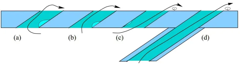
Burd and Simon [25] presents the effect of different types of cooling air delivery; counter flow, co-flow, short hole with unrestricted plenum and long hole with unrestricted plenum on the film cooling performance. Counter flow means the cooling air inside the plenum has an opposite direction to the mainstream flow. Meanwhile, for co-flow, the cooling air flow inside the plenum has same direction with the mainstream flow direction. Unrestricted plenum means the cooling air is delivered directly into the cooling hole without through any plenum. Thus, short and long hole with unrestricted plenum differentiate the length of the cooling hole with unrestricted plenum.
Figure 2.2: Flow streamlines model for (a) counter flow, (b) short hole with unrestricted plenum, (c) co-flow and (d) long hole with unrestricted plenum [25]
2.2.3 Streamwise angle of film cooling hole
a) Cylindrical hole b) Fan-shaped hole
Figure 2.3: Film cooling hole with streamwise angle, α [6, 26-30]
Other works on streamwise angle have also been reported by Ligrani and Lee [29] and McGovern and Leylek [30], which covered the cylindrical hole with a various streamwise angle. From both studies, the lateral spread of cooling air was improved and cooling air covering the wall better than cylindrical hole without a streamwise angle. However, as streamwise angle increase, the lateral spread was turned into one side. The kidney vortex also becomes asymmetrical and fundamentally alters the interaction of the cooling air and mainstream flow. Same as the Brittingham and Leylek [31] and Brauckmann and Wolfersdorf [6], the spread of cooling air also turned to one side as the streamwise angle increase on a fan-shaped film cooling hole and on a row of laidback fan-shaped film cooling holes. Although the application of streamwise angle altered the cooling air distribution, another method should be developed to cover the wall laterally and improved the one-sided wall covering.
2.3 Flow setting effect on the film cooling method
Besides the various geometrical parameter applied in film cooling field, several flow parameters; blowing ratio, density ratio and turbulence intensity also considered in some research to observe the change of the aerodynamic and thermal performance. In the early research of Bons et al. [32], the work considered the experimental study of a single row of cylindrical film cooling hole with 35o of cooling air injection to the mainstream flow. The elevated blowing ratio applied in the experimental study shows reduced in the film cooling effectiveness. The blowing ratio, M of 0.7 has better film cooling performance in comparison with a higher blowing ratio. In the other work of
Abu Talib et al. [33], the cylindrical film cooling hole with an inclination angle of 45o also produced better film cooling performance at blowing ratio, M = 0.64 in comparison with the high blowing ratio.
Ligrani and Lee [29] study the effect of high blowing ratio, M in the range of 1.5 – 4.0 on a row of cylindrical film cooling holes with a streamwise angle of 50.5o. The larger streamwise angle was considered to imitate the arrangement of rotating blades on the first stage of the operating gas turbine engine. In the study, the film cooling performance was reduced at elevated blowing ratio value, similarly with the previous study of Bons et al. [32]. The lift-off effect is the main cause of the separation of cooling air from covering the blade surfaces while lowering the overall film cooling performance. Therefore, increase the blowing ratio to M = 4.0 for cylindrical film cooling hole with a streamwise angle not producing better film cooling performance in comparison with the film cooling performance at M = 1.5.
In the other research of film cooling, Gritsch et al. [7] had focused on the effect of various blowing ratio on three different film cooling hole; cylindrical, fan-shaped and laidback fan-shaped film cooling hole. As the results shown, increased the blowing ratio cause the elevated heat transfer coefficient for all three different geometries. However, laidback fan-shaped cooling hole significantly improved film cooling performance as the heat transfer coefficient and film cooling effectiveness produced is better in comparison with cylindrical and fan-shaped film cooling hole.
of the cooling jets gives an advantage of high turbulence intensity. Improved film cooling coverage in the region between injection holes was observed as turbulence increase. However, the results also indicate that elevated freestream turbulence reduced the overall film cooling performance due to enhanced mixing.
Schmidt and Bogard [34] also carried out the experimental study of cylindrical film cooling hole with applying the high freestream turbulence. As an agreement to the Bons et al. [32] results, increasing the freestream turbulence reduces the film cooling performance. In summary, blowing ratio and turbulence intensity are important flow parameters that determine the performance of film cooling hole. The appropriate combination of blowing ratio and turbulence intensity can be applied at different film cooling hole design and configuration to optimize the overall film cooling performance.
2.4 Lift-off phenomena of the cooling air in the cylindrical film cooling hole
Figure 2.4: The kidney vortex formation of single cylindrical film cooling hole [35]
In addition, the lift-off effect also depends on the momentum of the cooling air. Studied by Leylek and Zerkie [36], the greater size of the vortex was formed and faster lift-off of cooling air has been observed as the momentum increase. The high momentum of the cooling air jet fails to attach to the surface and penetrates into the mainstream air. As the conclusion, lift-off phenomena occurred due to the entrainment of mainstream air occupying the area beneath the vortices and mixed with the vortices and consequently, lowering the overall film cooling performance of film cooling.
2.5 Combined-hole film cooling method with compound angle
Figure 2.5 presents the concept of kidney vortex formation from combined-hole film cooling with opposite compound angle which introduced by Han and Ren [37]. By adding a positive or negative compound angle on the cylindrical film cooling hole, one of the vortices existed in the kidney vortex formation was weakened while the other one was enhanced. Therefore, the anti-kidney vortex was produced by combining two pairs of asymmetrical vortices formed by combined-hole film cooling. A proper pitch distance applied on the combined-hole film cooling ensure the vortex is pushed to the wall by shear stress led by the rotation of the other vortex. The weakened vortex tends to spread the cooling air in lateral direction thus produced wide film cooling coverage along the streamwise direction.
fan-shaped and laidback film cooling holes. With the application of two cylindrical hole, the combined-hole film cooling is more preferred due to manufacturability of this cooling hole design.
Figure 2.6: Film cooling arrangement in Ahn et al. [10]
Figure 2.7: Different combined-hole configurations between (a) Kusterer et al. [38] and (b) Wright et al. [39]
Wright et al. [39] have also reported on the performance of combined-hole film cooling. However, the work has considered different combined-hole film cooling arrangement which is the hole was arranged side by side as shown in Figure 2.7 (b) and γ1 and γ2 are the compound angle applied on the combined-hole film cooling arrangement. Comparing the results experimentally with cylindrical and fan-shaped film cooling hole, the results show that combined-hole film cooling only succeeds to improve the film cooling effectiveness at near hole region. However, the performance
mainstream
(a) (b)
mainstream
[image:37.595.158.490.287.532.2]of fan-shaped film cooling hole shows better results and cover the wall more lateral compared to the combined-hole film cooling by Wright et al. Although the anti-kidney vortex existed in the case of combined-hole film cooling, narrow coverage was observed along streamwise direction due to the non-effective arrangements of hole and reduced the overall film cooling performance of this combined-hole film cooling.
[image:38.595.134.504.432.544.2]Besides combining two cylindrical holes, researchers also combined more than two cylindrical holes as a film cooling. Schulz et al. [40] combined three cylindrical holes known as an anti-vortex film cooling holes. Meanwhile, sister holes introduced by Ely and Jubran [41] is a combination of three to five cylindrical hole with different film cooling hole diameter. Both types of cooling holes produced the anti-kidney vortex which constrained the lift-off of cooling air and enhanced film cooling effectiveness. Both design also succeeds to improve film cooling effectiveness along the streamwise direction and produce more lateral film cooling coverage in comparison with the other film cooling hole.
Figure 2.8: Film cooling arrangement in Javadi et al. [42]
process with the hot mainstream air. The vortices also produced great momentum of cooling air to spread and covered the wall in the lateral direction. Therefore, the formation of other vortices is important in this study to enhance the film cooling performance in lateral and streamwise direction.
2.6 Aerodynamic performance of film cooling
The aerodynamic performance of film cooling usually characterizes by the qualitative result of total pressure loss coefficient contour or distribution and the quantitative result of total pressure loss coefficient graph. Figure 2.9 shows the total pressure loss coefficient contour in the research of Lee et al. [43]. The contour was taken from the plane of x/D = 8 for low blowing ratio, M = 0.5 in the case of cylindrical film cooling hole at a different streamwise angle. As shown in Figure 2.9, the large streamwise angle case of 90o produced larger total pressure loss coefficient in comparison with the other two cases at low blowing ratio. However, the insignificant change was produced on the total pressure loss coefficient graph as shown in Figure 2.10. Significant change only can be observed in the case of high blowing ratio of 1.0 and 2.0 where high total pressure loss coefficient was produced which indicate the low aerodynamic performance of film cooling hole.
Figure 2.9: Total pressure loss coefficient contour at x/D = 8 for low blowing ratio [43]
[image:40.595.161.476.381.671.2]REFERENCES
[1] General Energy Company, GE 9E – Heavy Duty Gas Turbine. Retrieved from
www.ge-spark.com. 2012.
[2] Moran, M. J., Shapiro, H. N., Boettner, D. D., & Bailey, M. B. Fundamentals of Engineering Thermodynamics. John Wiley & Sons. 2010.
[3] Hada, S., Tsukagoshi, K., Masada, J., & Ito, E. Test results of the world’s first
1,600 C J-series gas turbine. Mitsubishi Heavy Industries Technical Review.
2012. 49(1), pp. 18.
[4] Han, J. C., Dutta, S., & Ekkad, S. Gas turbine heat transfer and cooling technology. CRC Press. 2012.
[5] Beck, T. Laser drilling in gas turbine blades. Laser Technik Journal. 2011.
8(3), pp. 40-43.
[6] Brauckmann, D., & von Wolfersdorf, J. Influence of compound angle on
adiabatic film cooling effectiveness and heat transfer coefficient for a row of
shaped film cooling holes. ASME Turbo Expo 2005: Power for Land, Sea, and
Air. January 2005. pp. 39-47.
[7] Gritsch, M., Schulz, A., & Wittig, S. Film-cooling holes with expanded exits:
near-hole heat transfer coefficients. International Journal of Heat and Fluid
Flow. 2000. 21(2), pp. 146-155.
[8] Harrison, K. L., & Bogard, D. G. CFD predictions of film cooling adiabatic
effectiveness for cylindrical holes embedded in narrow and wide transverse
trenches. ASME Turbo Expo 2007: Power for Land, Sea, and Air. January,
2007. pp. 811-820.
[9] Bell, C. M., Hamakawa, H., & Ligrani, P. M. Film cooling from shaped holes.
Transactions-American Society of Mechanical Engineers Journal Of Heat
Transfer. 2000. 122(2), pp. 224-232.
[10] Ahn, J., Jung, I. S., & Lee, J. S. Film cooling from two rows of holes with
effectiveness. International Journal of Heat and Fluid Flow. 2003. 24(1), pp.
91-99.
[11] Kusterer, K., Elyas, A., Bohn, D., Sugimoto, T., Tanaka, R., & Kazari, M. A
parametric study on the influence of the lateral ejection angle of double-jet
holes on the film cooling effectiveness for high blowing ratios. ASME Turbo
Expo 2009: Power for Land, Sea, and Air. American Society of Mechanical
Engineers. January, 2009. pp. 199-211.
[12] Kusterer, K., Bohn, D., Sugimoto, T., & Tanaka, R. Influence of blowing ratio
on the double-jet ejection of cooling air. ASME Turbo Expo 2007: Power for
Land, Sea, and Air. American Society of Mechanical Engineers. January,
2007. pp. 305-315.
[13] Lee, K. D., Choi, D. W., & Kim, K. Y. Optimization of ejection angles of
double-jet film-cooling holes using RBNN model. International Journal of
Thermal Sciences, 73. 2013. pp. 69-78.
[14] Choi, D. W., Lee, K. D., & Kim, K. Y. Analysis and Optimization of
Double-Jet Film-Cooling Holes. Journal of Thermophysics and Heat Transfer, 27(2).
2013. pp. 246-254.
[15] Han, C., Chi, Z., Ren, J., & Jiang, H. Optimal arrangement of combined-hole
for improving film cooling effectiveness. Journal of Thermal Science and
Engineering Applications. 2015.
[16] Kusterer, K., Elyas, A., Bohn, D., Sugimoto, T., Tanaka, R., & Kazari, M. Film
cooling effectiveness comparison between shaped-and double jet film cooling
holes in a row arrangement. ASME Turbo Expo 2010: Power for Land, Sea,
and Air. American Society of Mechanical Engineers. October, 2010. pp.
1503-1515.
[17] Goldstein, R. J. Film cooling. Advances in heat transfer, 1971. 7(1), pp.
321-379.
[18] Brown, A., & Saluja, C. L. Film cooling from a single hole and a row of holes
of variable pitch to diameter ratio. International Journal of Heat and Mass
Transfer. 1979. 22(4), pp. 525-534.
[19] Berger, P. A., & Liburdy, J. A. A near-field investigation into the effects of
geometry and compound angle on the flowfield of a row of film cooling holes.
ASME 1998: International Gas Turbine and Aeroengine Congress and
[20] Goldstein, R. J., Eckert, E. R. G., & Burggraf, F. Effects of hole geometry and
density on three-dimensional film cooling. International Journal of Heat and
Mass Transfer. 1974. 17(5), pp. 595-607.
[21] Hyams, D. G., & Leylek, J. H. A detailed analysis of film cooling physics: Part
III - streamwise injection with shaped holes. ASME 1997: International Gas
Turbine and Aeroengine Congress and Exhibition. American Society of
Mechanical Engineers. June, 1997.
[22] Barigozzi, G., Benzoni, G., Franchini, G., & Perdichizzi, A. Fan-shaped hole
effects on the aero-thermal performance of a film-cooled endwall. Journal of
turbomachinery. 2006. 128(1), pp. 43-52.
[23] Kohli, A., & Bogard, D. G. Adiabatic effectiveness, thermal fields, and
velocity fields for film cooling with large angle injection. ASME 1995
International Gas Turbine and Aeroengine Congress and Exposition.
American Society of Mechanical Engineers. June, 1995.
[24] Yuen, C. H. N., & Martinez-Botas, R. F. Film cooling characteristics of a single
round hole at various streamwise angles in a crossflow: Part I
effectiveness. International Journal of Heat and Mass Transfer. 2003. 46(2),
pp. 221-235.
[25] Burd, S. W., & Simon, T. W. The influence of coolant supply geometry on film
coolant exit flow and surface adiabatic effectiveness. ASME 1997 International
Gas Turbine and Aeroengine Congress and Exhibition. American Society of
Mechanical Engineers. June, 1997.
[26] Schmidt, D. L., Sen, B., & Bogard, D. G. Film cooling with compound angle
holes: adiabatic effectiveness. ASME 1994: International Gas Turbine and
Aeroengine Congress and Exposition. American Society of Mechanical
Engineers. June, 1994.
[27] Sen, B., Schmidt, D. L., & Bogard, D. G. Film cooling with compound angle
holes: heat transfer. Journal of Turbomachinery. 1996. 118(4), pp. 800-806.
[28] Nasir, H., Ekkad, S. V., & Acharya, S. Effect of compound angle injection on
flat surface film cooling with large streamwise injection angle. Experimental
Thermal and Fluid Science. 2001. 25(1), pp. 23-29.
[29] Ligrani, P. M., & Lee, J. S. Film cooling from a single row of compound angle
holes at high blowing ratios. International Journal of Rotating
[30] McGovern, K. T., & Leylek, J. H. A detailed analysis of film cooling physics:
part II-compound-angle injection with cylindrical holes. Journal of
Turbomachinery. 2000. 122(1), pp. 113-121.
[31] Brittingham, R. A., & Leylek, J. H. A detailed analysis of film cooling physics:
Part IV - Compound–angle injection with shaped holes. ASME 1997:
International Gas Turbine and Aeroengine Congress and Exhibition.
American Society of Mechanical Engineers. June, 1997.
[32] Bons, J. P., MacArthur, C. D., & Rivir, R. B. The effect of high freestream
turbulence on film cooling effectiveness. ASME 1994 International Gas
Turbine and Aeroengine Congress and Exposition. American Society of
Mechanical Engineers. June, 1994.
[33] Talib, A. A., Jaafar, A. A., Mokhtar, A. S., Rahim, I. A., & Karim, M. A.
Effects of blowing ratio on the heat transfer coefficient distribution
downstream of a single film cooling hole. International Journal of
Engineering and Technology. 2006. 3(1), pp. 37-46.
[34] Schmidt, D. L., & Bogard, D. G. Effects of free-stream turbulence and surface roughness on film cooling. ASME 1996 International Gas Turbine and Aeroengine Congress and Exhibition. American Society of Mechanical Engineers. June, 1996.
[35] Fric, T. F., & Roshko, A. Vortical structure in the wake of a transverse jet. Journal of Fluid Mechanics. 1994. pp. 1-47.
[36] Leylek, J. H., & Zerkle, R. D. Discrete-jet film cooling: a comparison of computational results with experiments. ASME 1993: International Gas Turbine and Aeroengine Congress and Exposition. American Society of Mechanical Engineers. May, 1993.
[37] Han, C., & Ren, J. Multi-parameter influence on combined-hole film cooling
system. International Journal of Heat and Mass Transfer. 2012. 55(15), pp.
4232-4240.
[38] Kusterer, K., Bohn, D., Sugimoto, T., & Tanaka, R. Double-jet ejection of
cooling air for improved film cooling. Journal of Turbomachinery. 2007.
129(4), pp. 809-815.
[39] Wright, L. M., McClain, S. T., Brown, C. P., & Harmon, W. V. Assessment of
2013: Turbine Technical Conference and Exposition. American Society of
Mechanical Engineers. June, 2013.
[40] Schulz, S., Maier, S., & Bons, J. P. An experimental investigation of an
anti-vortex film cooling geometry under low and high turbulence conditions. ASME
Turbo Expo 2012: Turbine Technical Conference and Exposition. American
Society of Mechanical Engineers. June, 2012. pp. 1581-1593.
[41] Ely, M. J., & Jubran, B. A. Film cooling from short holes with sister hole
influence. ASME Turbo Expo 2012: Turbine Technical Conference and
Exposition. American Society of Mechanical Engineers. June, 2012. pp.
1185-1196.
[42] Javadi, A., Javadi, K., Taeibi-Rahni, M., & Darbandi, M. A new approach to
improve film cooling effectiveness using combined jets. Momentum. 2003. 2,
2.
[43] Lee, S. W., Kim, Y. B., & Lee, J. S. Flow characteristics and aerodynamic
losses of film-cooling jets with compound angle orientations. ASME 1995:
International Gas Turbine and Aeroengine Congress and Exposition.
American Society of Mechanical Engineers. June, 1995.
[44] Drost, U., & Bölcs, A. Performance of a turbine airfoil with multiple film
cooling stations: Part II - Aerodynamic losses. ASME 1999: International Gas
Turbine and Aeroengine Congress and Exhibition. American Society of
Mechanical Engineers. June, 1999.
[45] Mayhew, J. E., Baughn, J. W., & Byerley, A. R. The effect of freestream
turbulence on film cooling adiabatic effectiveness. International Journal of
![Figure 1.1: Modern gas turbine [1]](https://thumb-us.123doks.com/thumbv2/123dok_us/8754744.892618/17.595.171.467.549.708/figure-modern-gas-turbine.webp)
![Figure 1.2: T-s and P-ν diagram for Brayton cycle [2]](https://thumb-us.123doks.com/thumbv2/123dok_us/8754744.892618/18.595.118.525.313.518/figure-t-s-p-n-diagram-brayton-cycle.webp)
![Figure 1.3: Turbine inlet temperature of MHI gas turbines series [3]](https://thumb-us.123doks.com/thumbv2/123dok_us/8754744.892618/19.595.163.513.371.631/figure-turbine-inlet-temperature-mhi-gas-turbines-series.webp)
![Figure 1.4: Turbine blade with various cooling techniques [4]](https://thumb-us.123doks.com/thumbv2/123dok_us/8754744.892618/21.595.115.540.106.369/figure-turbine-blade-various-cooling-techniques.webp)
![Figure 2.1: Geometry of different film cooling hole design [7, 22]](https://thumb-us.123doks.com/thumbv2/123dok_us/8754744.892618/27.595.151.508.166.444/figure-geometry-different-film-cooling-hole-design.webp)
![Figure 2.3: Film cooling hole with streamwise angle, α [6, 26-30]](https://thumb-us.123doks.com/thumbv2/123dok_us/8754744.892618/31.595.177.480.71.174/figure-film-cooling-hole-streamwise-angle-a.webp)
![Figure 2.4: The kidney vortex formation of single cylindrical film cooling hole [35]](https://thumb-us.123doks.com/thumbv2/123dok_us/8754744.892618/34.595.116.526.68.277/figure-kidney-vortex-formation-single-cylindrical-film-cooling.webp)

![Figure 2.6: Film cooling arrangement in Ahn et al. [10]](https://thumb-us.123doks.com/thumbv2/123dok_us/8754744.892618/37.595.158.490.287.532/figure-film-cooling-arrangement-in-ahn-et-al.webp)
