International Journal of Emerging Technology and Advanced Engineering
Website: www.ijetae.com (ISSN 2250-2459, Volume 2, Issue 7, July 2012)461
Dynamic Performance Analysis of DFIG based Wind
Farm with STATCOM and SVC
Naimul Hasan
1(Corresponding Author), Ibraheem
2, Shuaib Farooq
31, 2,3Department of Electrical Engineering
Jamia Millia Islamia New Delhi, India 1
naimul_hasan @rediffmail.com 2[email protected]
Abstract—To meet the strict criteria of grid codes for the integrated wind farm with the grid has become a major point of concern for engineers and researchers today. Moreover voltage stability is a key factor for the stable operation of grid connected wind farm during fault ride through and grid disturbances. This paper investigates the implementation and comparison of FACTS devices like STATCOM and SVC for the voltage stability issue for DFIG-based wind farm connected to a grid and load. The study includes the implementation of FACTS devices as a dynamic voltage restorer at the point of common coupling to maintain stable voltage and thereby protecting DFIG-based wind farm interconnected powers system from isolating during and after the disturbances. The power system model is simulated in MATLAB / SIMULINK and the results show that the STATCOM is better than SVC for the stable operation of wind turbine generator system to remain in service during grid faults.
Keywords—wind power plant; doubly fed induction generator; transient stability; power system stability; FACTs
I. INTRODUCTION
With the penetration of renewable energy technologies into the electrical grids, wind energy has become high point of concern for the engineers and researchers for efficient conversion of wind energy into electrical energy and for the stable operation of wind farms with the electrical grid that leads to development of new technologies for wind energy conversion system. DFIG based variable speed wind energy conversion systems are currently the most widely accepted due to its numerous advantages [1].
International Journal of Emerging Technology and Advanced Engineering
Website: www.ijetae.com (ISSN 2250-2459, Volume 2, Issue 7, July 2012)462
II. AN OUTLINE OF FACTS DEVICES
Flexible AC Transmission Systems are represented by a group of power electronic devices. This technology was developed to perform the same functions as traditional power system controllers such as transformer tap changers, phase shifting transformers, passive reactive compensators, synchronous condensers, etc. Particularly FACTS devices allow controlling all parameters that determine active and reactive power transmission: nodal voltages magnitudes and angles and line reactance. Replacement of the mechanical switches by semiconductor switches allowed much faster response times without the need for limiting number of control actions. However, FACTS technology is much more expensive from the mechanical one FACTS devices can be divided into two generations. Older generation bases on the thyristor valve, where newer uses Voltage Source Converters (VSC). In both categories there are corresponding devices performing similar services. Generally speaking, VSC technology offers faster control over a wider range. Moreover, new generation does not need bulky reactors, thus size of these devices is considerably smaller than the thyristor controlled ones. However, VSC technology requires use of self commutating semiconductor devices which are more expensive, have higher losses and smaller voltage ratings when compared to the thyristors. Another way of categorizing FACTs devices is by the way they are connected to power systems shunt, series or shunt series connection [4]. Main purpose of shunt devices is to provide reactive power compensation and dynamic voltage support of the lines or loads. One of the shunt devices is the thyristor based Static VAR Compensator (SVC), which can be seen as a variable susceptance with a smooth control over a wide range from capacitive to inductive . It is the oldest FACTS device and has the biggest number of applications. VSC based Static Compensator (STATCOM) is another shunt connected device, which behaves like a synchronous voltage source which can inject or absorb reactive power. Biggest advantage of STATCOM over SVC is the ability to maintain the reactive current output at its nominal value over a wide range of node voltages, where SVC has limited current capability when voltage is reduced [5-7].
A. Static Synchronous Compensators (STATCOM)
The STATCOM system is one of the FACTs devices used in the integration of wind farms with Grid to improve the transient and steady state stability of the power system. STATCOM provides or absorbs reactive power to or from the grid to compensate small voltage variations at the connection point of the wind farm with the grid. STATCOM is also used when a voltage dip occurs. Many studies show that STATCOM helps the wind farm to stabilize voltage especially after a voltage dip occurs [11].
International Journal of Emerging Technology and Advanced Engineering
Website: www.ijetae.com (ISSN 2250-2459, Volume 2, Issue 7, July 2012) [image:3.612.48.288.120.248.2]463
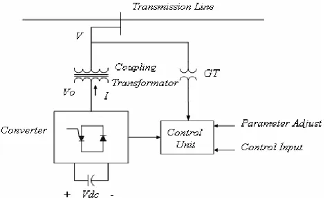
Figure 1. Schematic of STATCOM
The operating principle of STATCOM as shown in figure1 is as follows:
If V=Vs (pu values), no current flows through Rtr and Ltr. If V>Vs, current ows through Rtr and Ltr. As the impedance is essentially inductive, the current phasor is perpendicular to Vs and V voltages. STATCOM injects reactive current to the grid (Capacitive current).
If V < Vs, current flows through Rtr and Ltr. This time the current flow is opposite to the previous, which implies that STATCOM absorbs reactive power from the grid.
Figure 2. Operating principle of STATCOM STATCOM reactive current is determined by the difference between grid voltage and power converter voltage. Reactive current is independent of the voltage of the connection point of STATCOM and is limited by the capacity of the power converter and grid voltage variation. The operation area of STATCOM is determined in figure 2. The maximum inductive current is not assumed until a certain lower limit of the voltage. This is because the voltage drops across the coupling transformer as shown in figure 3. The STATCOM control system, d-q reference is possible to control d-q
[image:3.612.327.562.254.397.2]current independent of DC voltage and reactive power of STATCOM. The calculation of Re-active Power related to STATCOM DC voltage are expressed Q = -V2 B + kVdc VB cos(θ - α) – kVdc VG sin(θ - α) Here, V is the transmission voltage, B is the suseptance, k the modulation index, Vdc the capacitor voltage, alpha the thyristor firing angle, θ phase angle of the transmission line, G is the admittance of coupling transformation.
Figure 3. Systematic of STATCOM
B. Static Var Compensators (Svcs)
Static VAR compensators, commonly known as SVCs and provides an excellent source of rapidly controllable reactive shunt compensation for dynamic voltage control through its utilization of high-speed thyristor switching/controlled reactive devices. An SVC is typically made up of the following major components:
1. Coupling transformer 2. Thyristor valves 3. Reactors
[image:3.612.48.283.449.563.2]International Journal of Emerging Technology and Advanced Engineering
Website: www.ijetae.com (ISSN 2250-2459, Volume 2, Issue 7, July 2012)464
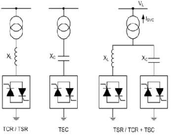
[image:4.612.71.245.310.449.2]Figure 4 shows these configurations: the Thyristor Controlled Reactor (TCR), the Thyristor Switched Reactor (TSR) and the Thyristor Switched Capacitor (TSC) or a combination of all three in parallel configurations. The TCR uses firing angle control to continuously increase/decrease the inductive current whereas in the TSR the inductors connected are switched in and out stepwise, thus with no continuous control of firing angle. Usually SVC‗s are connected to the transmission lines, thus having high voltage ratings [12-13]. Therefore the SVC systems have a modular design with more thyristor valves connected in series/ parallel for extended voltage level capability.
Figure 4. Systematic of TSC/TCR (SVC)
Generally, the two thyristor valve controlled/switched concepts used with SVCs are the thyristor - controlled reactor (TCR) and the thyristor-switched capacitor (TSC). The TSC provides a ―stepped‖ response and the TCR provides a ―smooth‖ or continuously variable susceptance. The SVC can be operated in two different modes: In voltage regulation mode and in Var control mode (the SVC susceptance is kept constant). When the SVC is operated in voltage regulation mode, it implements the following V-I characteristic. As long as the SVC susceptance B stays within the maximum and minimum susceptance values imposed by the total reactive power of capacitor banks (Bcmax) and reactor banks (BLmax), the voltage is regulated at the reference voltage Vref. However, a voltage droop is normally used (usually between 1% and 4% at maximum reactive power output), and the V-I characteristic has the slope indicated in the figure.5.
The V-I characteristic and operating region of SVC is described by the following three equations:
SVC is in regulation range (-Bmax< B <BLmax) V = Vref * Xs * I
V = I / Bcmax
SVC is fully capacitive (B = Bcmax) V = I / BImax
SVC is fully inductive (B = BLmax) V is the positive sequence voltage (p.u.)
I is the reactive current (p.u./Pbase) (I > 0 indicates an inductive current)
Xs is the Slope or droop reactance (p.u./Pbase)
Bcmax is the maximum capacitive susceptance (p.u./Pbase) with all TSCs in service, no TSR or TCR
BLmax is the Maximum inductive susceptance (p.u./Pbase) with all TSRs in service or TCRs at full conduction, no TSC
Pbase is the three-phase base power
Figure 5. The V-I Characteristic of SVC
III. POWER SYSTEM MODEL
[image:4.612.361.515.445.596.2]International Journal of Emerging Technology and Advanced Engineering
Website: www.ijetae.com (ISSN 2250-2459, Volume 2, Issue 7, July 2012) [image:5.612.64.254.120.288.2]465
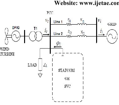
Figure 6. Single line diagram of power system network Generally an integrated power system, wind farm consists of multiple wind turbines is connected with the grid to supply power to the grid and the point of interconnection is known as point of common coupling as shown in figure 6. A STATCOM or SVC can be placed at the PCC between the wind farm and the power system network and with well-tuned converters, there is no mutual interaction between wind turbines in a wind farm, and operates independently from the conditions of the grid. Therefore in this paper, only one wind turbine is used to represent the wind farm. To understand characteristic behavior of DFIG based wind turbine many techniques have been developed under different d-q control conditions. Broadly divided into two categories:
1) Transient approaches 2) Steady-state techniques
The transient approaches are essential to study DFIG dynamic performance in a short time period and steady-state techniques are important to examine DFIG characteristics under different control conditions in a detailed manner. Steady-state approach plays an important role to examine DFIG characteristics under different conditions in a broader spectrum and also in the design and development of highly advanced control schemes. Unlike fixed speed turbines, DFIG delivers power to the grid from both the stator and rotor paths. The stator of the generator is directly connected to grid while the rotor is connected to the grid through PWM power converters.
The DFIG frequency converter can be a potential cause of concern for effective control of a DFIG system. Therefore, in the steady-state characteristic study of a DFIG system, specific regularities like power transferred through both the paths should be considered carefully. It is very important to consider these factors in the steady-state study to enhance proper analysis, design and management of wind energy conversion systems that make use of DFIGs. From a different point of view, although d-q vector control technique regulates DFIG speed, it also changes the basic parameters of the DFIG such as torque, stator real/reactive power, rotor real/reactive power and the effectiveness of PWM converter modulation.
Basically there are two conventional modes of wind turbine operation one is normal mode condition and second is the fault mode condition.
a) The Normal Mode Condition
For wind speed smaller than the nominal rotor side converter (RSC) controls the speed of the generator to follow the maximum energy extraction (speed is variable) and the power factor and the blade pitch angle control is set to 0º (maximum energy capture), grid side controller regulates the DC link voltage between the two converters in a fixed point. However for wind speed greater than the nominal speed rotor side converter (RSC) controls the speed of the generator to a fixed point. The blade pitch angle is controlled to limit the energy capture from the wind in order to do not overcome the generator nominal characteristic. Grid side converter (GSC) regulates the DC link voltage between the two converters .In this paper normal mode operation is considered for simulation and comparison of STATCOM and SVC for steady state stability.
b). Fault Mode Condition
International Journal of Emerging Technology and Advanced Engineering
Website: www.ijetae.com (ISSN 2250-2459, Volume 2, Issue 7, July 2012)466
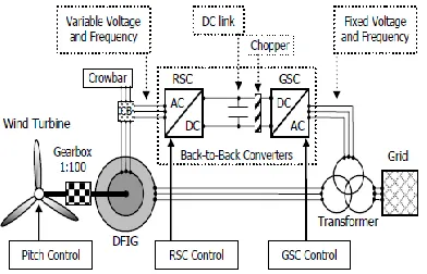
[image:6.612.336.558.251.374.2]Some undesirable high currents may be induced in the rotor windings because the stator windings of the DFIG are directly connected to the network. In conventional DFIG (without fault ride through), the protection system may block the RSC. However, the DFIG with fault ride through is equipped with a crowbar system to limit the high induced currents on the rotor windings. The voltage at the DC-link is another undesirable transient, which can reach high levels, related to the unbalance of active power between RSC and GSC. The very low residual terminal voltage during the fault and the slow velocity of the RSC disconnection from the rotor winding, after fault detection, would cause such unbalance. The crowbar system transforms the DFIG behavior in a conventional squirrel-cage induction generator expanding the rotor critical speed for the period of the RSC disconnection from the rotor winding. The chopper system is used to dissipate the unbalance of active power between RSC and GSC. These devices can be seen in figure 7.
Figure. 7: DFIG with back-to-back PWM voltage source converters
c) Control system for rotor side converter (RSC)
Under normal mode operation, the rotor-side converter controls the injection of reactive power and the developed electric power (Pelec). In this operation point the optimum
electric power reference (P* opt) is calculated taking into account the optimal rotor speed for the incoming wind by the maximum value of the Cp curves. As shown in figure 8, an encoder can give the generator rotor position (θ) to the abc-dq0 and to the dq0-abc transformations. The direct axis component is used to maintain the generator power factor
[image:6.612.52.248.398.524.2]in 1pu thus, the absorbed reactive power reference (Q*) is equal to 0 (zero). The quadrature axis component is controlled in a similar way of the direct axis, however, it regulates the electric power to the optimal value (P*opt). The V*d and V*q reference signals are send to the dq0-to-abc transformation and, then, to the signal generator based on the PWM (Pulse-width Modulation) methodology. V*abc are the three phase voltages desired at RSC output.
Figure. 8:RSC control system
Under fault mode condition, the high resistance is required as the terminal voltage drops below 0.8 pu, then normal mode operation control scheme is stopped and the three phase series resistance is inserted to the rotor windings to prevent the rotor side converters as shown in figure7.
d) Control system for grid side converter (GSC)
International Journal of Emerging Technology and Advanced Engineering
Website: www.ijetae.com (ISSN 2250-2459, Volume 2, Issue 7, July 2012) [image:7.612.66.284.140.279.2]467
Figure. 9:GSC control system
Under fault mode condition, the voltage of the DC link can reach high level depends on the active power unbalance between RSC and GSC. This unbalance can be greater for low the residual terminal voltage during fault and for slowly disconnection of the RSC from the rotor winding after fault detection. The use of the DC chopper can dissipate the power unbalance; however, the GSC maintains the control of the DC link voltage in the same time. After the fault detection, GSC switches the quadrature axis current reference (I*q =0) to terminal voltage control [14-16].
IV. SIMULATION RESULTS
The investigated power system network is modeled and simulated in MATLAB / SIMULINK as shown in figure 10 to study the steady state behavior with STATCOM and SVC. All the parameters are given in Appendix.
Figure. 10:Simulink model of DFIG with STATCOM and SVC
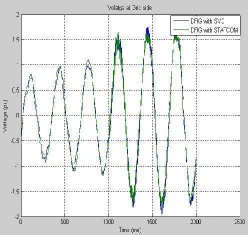
[image:7.612.325.573.291.526.2]Both the system, DFIG with STATCOM and other DFIG with SVC is operated with same load of 200kW connected at PCC. The system is tested under the voltage regulation mode of STATCOM and SVC to analyze and compare the behavior of both the system on the basis of voltage and reactive power flow at PCC. As shown in figure 11 disturbance in grid voltage and harmonics generated when the breaker of load of 200kW at common coupling bus is closed at time 0.001 sec is shown in figure 11.The SVC have a higher effect of harmonics and flickering creating disturbance on grid voltage.
Figure. 11: Grid side Voltage profile of interconnected DFIG based wind farm
[image:7.612.48.294.525.682.2]International Journal of Emerging Technology and Advanced Engineering
Website: www.ijetae.com (ISSN 2250-2459, Volume 2, Issue 7, July 2012) [image:8.612.54.284.131.319.2]468
Figure. 12: Voltage profile point of common coupling of DFIG based wind farm
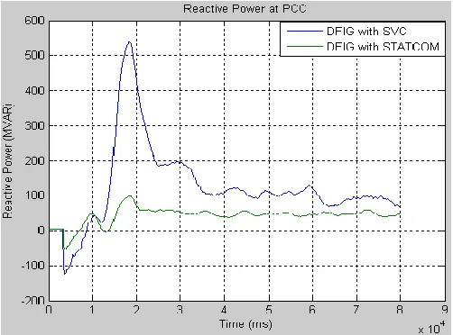
[image:8.612.48.299.480.666.2]However analyzing the reactive power flow for stabilizing the system voltage then it is quite clear from from figure 13 that under the same condition of voltage instability the reactive power in case of STATCOM is -50Mvar as compared to SVC which shoots the reactive power upto -100Mvar and then settling time and reactive power for the stable operation of the system is also quite low in the case of STATCOM.
Figure. 13: Reactive power at PCC for DFIG with STATCOM and SVC
V. CONCLUSION
The steady state behaviour of an interconnected DFIG based wind farm with STATCOM and SVC is studied and compared for performance evaluation of the two FACTs devices. . A case was developed in which when the load is connected at the point of common coupling there is a voltage dip which if not timely corrected then it will eventually leads to voltage instability of interconnected power system, the responses of both the system is analyzed and is found that STATCOM and SVC have made the voltage and reactive power made them stable but the STATCOM yielded better results in terms of time response than SVC in voltage control. Reactive power wise, it was found that STATCOM becomes stable in a shorter time span relative to SVC.
VI. APPENDIX
PARAMETERS OF SIMULATED DFIG
Rated power 3 MW
Stator Voltage 575 V Rs (stator resistance) 0.0071 pu
Rr (rotor resistance) 0.005 pu (ref to stator) Ls (stator inductace) 0.171 pu
Lr (rotor inductance) 0.156 (ref to stator) Lm(magnetizing inductance) 2.9 pu
Number of pole pairs 3 Inertia constant 5.04
SVC 100 MVAR
International Journal of Emerging Technology and Advanced Engineering
Website: www.ijetae.com (ISSN 2250-2459, Volume 2, Issue 7, July 2012)469 References
[1] Sol-Bin Lee, Kyo-Beum Lee, Dong-Choon Lee and Jang-Mok Kim ―An Improved Control Method for a DFIG in a Wind Turbineunder an Unbalanced Grid Voltage Condition‖ Journal of Electrical Engineering & Technology Vol. 5, No. 4, pp. 614~622, 2010
[2] B. Pokharel and Wenzhong Gao, ―Mitigation of disturbances in DFIG-based wind farm connected to weak distribution system using STATCOM,‖ in Proc. IEEE North American Power Symposium, pp. 1-7, 26-28 Sept. 2010.
[3] J. Machowski, J.W. Bialek, J.R. Bumby, Power System Dynamics –Stability and Control, John Wiley & Sons, 2008 [4] B. Sookananta, S. Galloway, G. M. Burt and J. R.
McDonald, ―The Placement of FACTS Devices in Modern Electrical Network‖, UPEC,2006
[5] A. Petersson, T. Petru, and T. Thiringer, ―Grid Disturbance Response of Wind Turbines Equipped with Induction Generator and Doubly-Fed Induction Generator‖, in Proceedings of 2003 IEEE PES General Meeting, Toronto, Canada, July 13-17, 2003.
[6] J.G Slootweg, S.W.H. de Haan, H. Polinder, and W.L Kling, ―General Model for Representing Variable Speed Wind Turbines in Power System Dynamics Simulations‖, IEEE Transactions o Power Systems, Vol. 18, No. 1, February 2003.
[7] J. Feltes, Y. Kazachkov, R. Zavadil, ―Modeling Wind Farms for Power System Stability Studies‖, Procedings of 2003 IEEE Power Engineering Society General Meeting, Toronto, Canada, 13-17 July 2003.
[8] S. Smith, R. Todd, M. Barnes, P.J. Tavner, ―Improved energy conversion for doubly-fed wind generators‖, IEEE Transaction on Industry Applications, Vol. 42, No. 6, pp. 1421-1428, November 2006.
[9] P. Ledesma, J. Usaola, and J.L Rodriguez, ―Models of WECS for Power System Dynamic Studies‖, Proceedings of the 33rd Universities‘ Power Engineering Conference (UPEC‘98), Edinburgh, U.K 8-10 September 1998.
[10]D. Beato, J.L Fernandez, R. Iturbe, P. Ledesma, J.M Rodriguez, J. Usaola, and J.R Wilhelmi, ―Transient Stability Studies in Grids with Great Wind Power Penetration: Modelling Issues and Operation Requirements‖, Proceedings of 2003 IEEE Power Engineering Society General Meeting, Toronto, Canada, 13-17 July 2003.
[11]F.W. Koch, I. Erlich, and F. Shewarega, ―Dynamic simulation of large wind farms integrated in a multi machine network‖, Proceedings of 2003 IEEE Power Engineering Society General Meeting, Toronto, Canada, 13-17 July 2003. [12]M.G. Ioannides, J.A. Tegopoulos, ―Generalized optimization slip power recovery drives‖, IEEE Transactions on Energy Conversion, Vol. 5, No. 1, pp. 91-97, March 1990.
[13]I. Cadirci, M. Ermis, ―Double-output induction generator operating at sub synchronous and super synchronous speeds: Steady-state performance optimization and wind-energy recovery‖, IEEE Proceedings-Electric Power Applications, Vol. 139, No. 5, pp. 429-442, September 1992.
[14]M.S. Vicatos, J.A. Tegopoulos, ―Steady state analysis of a doubly-fed induction generator under synchronous operation‖, IEEE Transaction on Energy Conversion, Vol. 4, No. 3, pp. 495-501, September 1989.
[15]P.C. Krause, O. Wasynczuk, M.S. Hildebrandt, ―Reference frame analysis of a slip energy recovery system‖, IEEE Transactions on Energy Conversion, Vol. 3, No. 2, pp. 404-408, Jume 1988.