SAAD ALI ASSI
Aproject report is Submitted In partial Fulfillment of the Requirements for The Award of The Degree of Master of Electrical Engineering
Faculty of Electrical and Electronic Engineering University Tun Hussein Onn Malaysia
JANUARY 2016
DEDICATION
This dissertation is dedicated to my parents, my brothers,
My sisters, my nieces and nephews
My lecturers and all my friends
That have encouraged, guide and inspired me throughout
ACKNOWLEDGEMENTS
First my praise to Almighty Allah for giving me the power and will to complete this study and peace be upon his final Prophet and Messenger Muhammad, SAW.
I would like to express my appreciation to my supervisor, Dr. NOR
SHAHIDA BINTI MOHD SHAH for his invaluable advice, guidance, support
and motivation to accomplish this project, without his continued support and interest, this project cannot be achieved.
I gratefully thank all the staff of the Department of Electrical and Electronic Engineering, UTHM University to give me the chance to study master degree.
ABSTRACT
ABSTRAK
Skema akses radio yang popular digunakan oleh system generasi ketiga (3G) adalah
CONTENTS
TITLE ii
DECLARATION iii
DEDICATION iv
ACKNOWLEDGEMENT v
ABSTRACT vi
ABSTRAK vii
CONTENTS viii
LIST OF TABLES xi
LIST OF FIGURE xiv
LIST OF APPENDICES xiv
LIST OF SYMBOLS AND ABBREVIATIONS xv
CHAPTER 1 INTRODUCTION
1.1 Introduction 1
1.2 Problem Statement 2
1.3 Aims and Objectives 2
1.4 Scope of Project 3
1.5 Project outline 3
CHAPTER2 LITERATURE REVIEW
2.1 Introduction 4
2.2 WCDMA System 5
2.2.1 WCDMA in 3G System 5
2.2.3 Classification of Services Provided in 8 WCDMASystem
2.3 Spreading and De-spreading 8
2.3.1WCDMA and the Spreading Concept 8
2.3.2 Spreading and De-spreading in DS-SS 9
2.3.3 Processing Gain 10
2.3.4 Scrambling 10
2.3.5 WCDMA System Codes 11
2.4 Multipath and RAKE Receiver 12
2.4.1 Multipath 12
2.4.2 RAKE Receiver 13
2.5 Frequency Reuse 14
2.6 Power Control and Handover in WCDMA 15
2.6.1 Power Control in WCDMA 15
2.6.2 Handover in WCDMA 15
2.7 Radio Access Network Architecture for WCDMA 17
2.8 Radio Network Planning 18
2.8.1 Dimensioning 19
2.8.2 Detailed Planning 19
2.8.3 Optimisation 22
2.9 Topology Planning 22
2.9.1 Initial Topology Planning 22
2.9.2 Detailed Topology Planning 23
CHAPTER 3 METHODOLOGY
3.1 Introduction 25
3.2 Flow chart 26
3.3Simulation in General 27
3.3.1 Dynamic Simulation 27
3.3.2 Static Simulation 28
3.4 NPSW Program 28
3.4.1 General Initialization Phase 29
3.4.1.1 Link Loss Calculations in 31
3.4.2 Iteration Phase 36
3.4.3 Post Processing Phase 38
3.5 Coverage Area Enhancement Methods 38
3.5.1 Mast Head Amplifiers 38
3.5.2 WCDMA Repeaters 40
3.5.2.1 Repeater Equipment 41
3.5.2.2Repeater Gain 43
3.5.2.3Repeater Delay 43
3.5.2.4 Repeater Distance 44
3.5.2.5Repeater Transmission Path 44
3.5.2.6 Thermal Noise in Repeater 46
Transmission Path
3.5.2.7 Repeater in WCDMA Network 47
CHAPTER 4 SIMULATION OF THE PROPOSED MODEL AND RESULTS
4.1 Introduction 49
4.2 Simulation Model Description 49
4.2.1 Sites Distribution 49
4.2.2 Users Distribution 52
4.2.3 Radio Network Parameters 53
4.3 Results of the Coverage Area Enhancement 54
4.3.1 Mast Head Amplifiers Results 54
4.3.2 WCDMA Repeater Results 55
CHAPTER FIVECONCLUSIONS AND FUTURE WORK
5.1 Introduction 66
5.2 Conclusion 66
5.3 Future Works 67
LIST OF TABLES
2.1 Evaluation of Mobile Communication Systems 5
2.2 The Main Parameters of WCDMA System 6
2.3 WCDMA Data Rate with Processing Gain 10
2.4 WCDMA system codes 11
2.5 Example of a radio link budget for speech and data services 21
3.1 A and B constants for the Okumura–Hata model 32
3.2 Parameter definitions for transmission path of repeater 46 3.3 Parameter definitions for the repeater block diagram 47
4.1 Fixed parameter values for BSs and UEs 53
4.2 Fixed parameter values for repeaters 53
LIST OF FIGURES
2.1 Allocation of Bandwidth in WCDMA in the time-frequency-code 7
space
2.2 Spreading and the De-spreading Operation 9
2.3 Spreading and Scrambling Process 11
2.4 Propagation Component 12
2.5 RAKE Receiver 13
2.6 Frequency Reuse Factor 14
2.7 Soft handover between two cells 16
2.8 Softer handover between two sectors 16
2.9 WCDMA Radio Access Network 17
2.10 Radio network planning process in WCDMA 19
2.11 Data rate with coverage 23
3.1 Flow chart of the project 26
3.2 NPSW program with a screenshot for Espoo city 29
3.3 The flow chart of the NPSW program 30
3.4 Horizontal and vertical plane 34
3.5 The azimuth and the elevation angle 35
3.6 The cascaded receiver subsystem components 39
3.7 Typical WCDMA BS receiver sub systems 40
3.8 A comparison of analogue, digital and WCDMA repeaters 41
3.9 An illustration of repeater system 42
3.10 Repeater self oscillation phenomenon 43
3.11 Different repeater distance 44
3.12 Transmission path for repeater installation 45
3.13 Repeater system block diagram 46
4.1 19 sites with one sector 50
4.2 19 sites with three sectors 50
4.4 19 sites with six sectors 51
4.5 User distribution for 8kbps 52
4.6 User distribution for 12.2,64,144 and 384 kbps 52
4.7 EFB and EFR with Gr=60dB 56
4.8 EFB and EFR with Gr=65dB 56
4.9 The impact of the repeater noise figure on the noiserise 57 4.10 Network with repeaters at 1000m from the donor BS103 58
4.11 Network with repeaters at 1200m from the donor BS 58
LIST OF APPENDICES
APPENDIX TITLE PAGE
LIST OF SYMBOLS AND ABBREVIATIONS
ALBS BS antenna loss.
a(hm) The UE antenna correction factor.
BSx position The BScoordinate in x-axis.
BSy position The BScoordinate in y-axis.
CLBS The cable loss in the base station.
csector The correlation coefficients of the two propagation paths from a UE to two sectors at the same site.
csite The correlation coefficient for two propagation paths from a UE to two sectors at different sites.
D The intended area sector size.
dkm Distance between UE and BS (km).
ds Distance between repeater and BS.
Da Distance between UE and BS (m).
Eb/No The energy per user bit divided by the noise spectral density.
F The frequency reuse factor.
f Carrier frequency.
FB BS noise figure.
FR Repeater noise figure.
Gp Processing gain.
GBS BS antenna gain.
GUE UE antenna gain.
GD Repeater donor antenna gain.
GR Repeater gain.
GS Repeater service antenna gain.
GB All gains in the BS.
GT The gains and losses between the repeater and BS.
hb BS antennas height.
hm UE antennas height.
Ioth,k The other cell interference.
i The ratio of the other cell interference to the own cell interference.
K Boltzmann’s constant.
LP Path loss.
P
L Average path loss.
Lp Link loss between repeater and BS.
Ls Link loss between UE and repeater.
Lkm The path loss from cell k to the UEm.
N Number of users in a cell.
Ns Number of users per sector.
Nimp Number of users with imperfect sectorisation.
NF Noise figure.
Nm The background and receiver noise of the UEm.
NiB Noise power at the input of the BS.
No Noise power at the output of the BS.
NTH Thermal noise density.
Pk Total transmit power of the BS to which link k is established.
Pkm The power allocated fromBSk to UEm.
R Is the user data rate.
Rj Data rate of user j.
Rb Bit rate of the modulated signal.
SiB Signal power at the input of the BS.
So Signal power at the output of the BS.
T The noise temperature.
TaB Antenna noise temperature at the BS antenna.
TaR Antenna noise temperature at the repeater service antenna.
TeB Inherent noise temperature of the BS.
TeR Inherent noise temperature of the repeater.
vj Activity factor of user j.
W Chip rate.
UL
η
Uplink load factor.DL
η
Downlink load factor.Α Theorthogonality factor.
αj The orthogonality factor of user j.
αi Is the direction of the UE relative to the BS.
ζ Log-normal random variable represents the shadowing
attenuation.
ξ Fading propagation path for UE.
σ Standard deviation of shadowing.
ϕ The azimuth angle.
𝜗𝜗 The elevation angle.
β The vertical angle between BS and UE antenna.
∆ The number of sectors per cell.
Є Overlap angle between sectors.
1G First Generation.
2G Second Generation.
3G Third Generation.
3GPP Third Generation Partnership Project.
4G Fourth Generation.
AMPS Advanced Mobile Phone Service.
AMR Adaptive Multi Rate.
AGC Automatic Gain Control.
BoD Bandwidth on Demand.
BS Base Station.
BPSK Binary Phase Shift Keying.
C/I Carrier to Interference Ratio.
CDF Cumulative Distribution Function.
CN Core Network.
Cu Is the electrical interface between the USIM smartcardand the ME.
CPICH Common Pilot Channel.
DL Downlink.
DS Direct Sequence.
DCH Dedicated Channel.
DS-SS Direct Sequence Spread Spectrum.
DTX Discontinuous Transmission.
DS-CDMA Direct Sequence Code Division Multiple Access.
EDT Electrical Down Tilt.
ETACS European Total Access Cellular System. EIRP Effective Isotropic Radiated Power.
EFB Effective Base Station noise figure.
EFR Effective noise figure for Repeater.
FDD Frequency Division Duplex.
FH-SS Frequency Hopping Spread Spectrum.
GSM Global System for Mobile.
GPS Global Positioning System.
HCS Hierarchical Cell Structure.
HSPA High Speed Packet Access.
IS-95 Interim Standard-95.
Iu The interface used for communication between the RNCand the core network.
Iub The interface used for communication between the NodeB and the RNC.
Iur The interface used for communication between different RNCs.
IF-HO Inter Frequency Handover.
IP Internet Protocol.
ISI Inter-Symbol Interference.
LOS Line of Sight.
LFS Free Space Loss.
ME Mobile Equipment.
MRC Maximal Ratio Combining.
MHAs Mast Head Amplifiers.
MDT Mechanical Down Tilt.
NF Noise Figure.
RAN Radio Access Network.
RRHs Remote Radio Heads.
RNC Radio Network Controller.
RRM Radio Resource Management.
RNP Radio Network Planning.
RF Radio Frequency.
SHO Soft Handover.
TDD Time Division Duplex.
TH-SS Time Hopping Spread Spectrum.
UE User Equipment.
UL Uplink.
UMTS Universal Mobile Telecommunication System.
USIM UMTS Subscriber Identity Module.
UTRA Universal Terrestrial Radio Access.
UTRAN UMTS Terrestrial Radio Access Network.
Uu The interface used for communication between the Node
and the UE.
CHAPTER 1
INTRODUCTION
1.1 Introduction
The cellular communication evolution has been very rapid in the past decade, the current mobile communication system family can be categorized into different generations; Analog based first generation (1G), circuit switched second generation (2G), packet switched third generation (3G) and lately Internet Protocol (IP) based fourth generation (4G). However, with the technology developments, each proceeding generation provides better quality, capacity and bandwidth efficient thus allowing wide range of services to be offered [1][2].
The most popular radio access scheme used for 3G system is Wideband Code Division Multiple Access (WCDMA), which allows greater capacity and higher data rate (up to 2Mbps) [3]. However, WCDMA radio access technique results in new difficulties for the radio network planners, because it allowed to use common frequencies in all cells of the network. Therefore, the coverage planning for WCDMA network is done because of the other to own cell interference phenomenon [4].
1.2 Problem Statement
The most popular radio access scheme used for the third generation (3G) system is Wideband Code Division Multiple Access (WCDMA), which provides high data rate services (video conferencing, high bit rate up to 2Mbps) compared with first (1G) and second (2G) generations. To obtain good services, increased reliable coverage area with minimum implementation cost, the planners must utilize all possible resources to improve coverage area for the cellular network.
1.3 Objectives
The objectives of this project are:
I. To investigate the influence of the mast head amplifiers and repeaters on the coverage area.
1.4 Scope of Project
I. The area of study is a cellular network in urban area with 13*13 km containing 19 sites.
II. Network Planning Strategies for WCDMA (NPSW) is a static simulation program used to plan the radio network for WCDMA system programmed with MATLAB.
1.5 Project Outline
The project consists of five chapters. Chapter one includes an introduction and the objectives, motivation of work, scope and thesis outline.
Chapter Two gives a brief explanation of the previous related literatures and detailed explanation for WCDMA system and radio network planning.
Chapter Three describes planning tool with types, explain Network Planning Strategies for Wideband CDMA (NPSW) program and explain methods of coverage area enhancement used in the present project.
Chapter Four gives a complete descriptions of the proposed simulation model and results as well as the discussions of results.
CHAPTER 2
LITERATURE REVIEW
2.1 Introduction
Wireless communication has encountered enormous development during the last three decades. The developments started from the 1G analog systems in 1983 such as Advanced Mobile Phone Service (AMPS) and the European Total Access Cellular System (ETACS) [1].
In the early 1990s, the 2G digital cellular systems began to be deployed, such as Global System for Mobile (GSM), while 1G can support voice service only and no privacy. 2G provides voice service as well as low data bit rate service, so the demand for multimedia and high data rate services (up to 2 Mbps) has led to the development of the 3G system [3][4].
Table 2.1 illustrates the evaluation of mobile communication systems.
Table 2.1: Evaluation of Mobile Communication Systems [1]
First Generation Second Generation Third Generation
AMPS, ETACS GSM, IS-95 UMTS, CDMA2000
Speech service
Speech service Low data rate service
Speech service Multimedia service High data rate service Analog transmission Digital transmission Digital transmission
2.2 WCDMA System
2.2.1 WCDMA in 3G Systems
The 3G systems are designed for multimedia communication, personal-to-personal communication can be enhanced with high quality images, video, and high data rate. WCDMA technology has emerged as the most widely is the 3G systems and with specification created in 3G Partnership Project (3GPP). With 3GPP, WCDMA is called Universal Terrestrial Radio Access (UTRA) either Frequency Division Duplex (FDD) or Time Division Duplex (TDD). WCDMA is a multiple access technology used in UMTS. The user information bits are spread over a band of 5MHz, which is nominal of all 3G WCDMA. This bandwidth is chosen because it is sufficient to provide data rate of 144 and 384 kbps and even 2 Mbps in good conditions [3][5].
2.2.2 Summary of the Main Parameters in WCDMA
Table 2.2: The Main Parameters of WCDMA System [5]
Multiple access technique DS-CDMA
Duplexing mode FDD and TDD
Chip rate 3.84 Mcps
Frame length 10 ms
Service multiplexing Multiple service in connection
Detection Coherent detection
Handover Soft handover
Multi user detection ,smart antenna Supported by the standard , optional in the implementation
The effective parameters of WCDMA are presented in this section [5][6]:
• WCDMA is a wideband Direct-Sequence Code Division Multiple Access
(DS-CDMA) system. User information bits are spread over a wide bandwidth (5 MHz) by multiplying the data with a spreading code, in order to support very high bit rates (up to 2Mbps), the use of a variable spreading factor and multicode connections are supported. An example of this arrangement is shown in Figure 2.1.
• The chip rate of 3.84Mcps leads to a carrier bandwidth of approximately 5 MHz. The inherently wide carrier bandwidth of WCDMA supports high user data rates and also has certain performance benefits, such as increased multipath diversity.
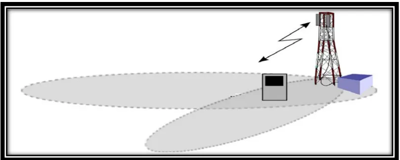
• WCDMA supports highly variable user data rates, in other words the concept
of obtaining Bandwidth on Demand (BoD) is well supported. The
user’s data rate is kept constant during each 10 ms frame. However, the data capacity among the users can be changed from one frame to another
Figure 2.1: Allocation of bandwidth in WCDMA in the time– frequency– code space [5]
• WCDMA supports two basic modes of operation: FDD and TDD. In the
FDD mode, separate 5MHz frequencies are used for the uplink and downlink respectively, whereas in TDD only one channel of 5MHz is time-shared between both the uplink and downlink. Uplink is the connection from the mobile to the base station, and downlink is that from the base station to the mobile.
• WCDMA supports the operation of asynchronous base stations, so that,
unlike the case in the synchronous IS-95 system, there is no need for a global time reference such as a Global Positioning System (GPS).
• WCDMA employs coherent detection on uplink and downlink based on the
use of pilot symbols or common pilot. In IS-95 coherent detection is only used on the downlink. The use of coherent detection on the uplink will result in an overall increase of the coverage and the capacity on the uplink.
2.2.3 Classification of Services Provided in WCDMA System
WCDMA system offers different types of service, and each service have certain data rate. The following are common data rate in WCDMA system [5]:
- 8kbps: This service provides the basic speech service.
- 12.2kbps: This service provides good quality speech service, including Adaptive Multi Rate (AMR) codec (AMR is a speechencoder).
- 64kbps: This service provides good quality speech and data service, with simultaneous data and AMR speech capability.
- 144kbps: This service provides video telephony (real time) or various other data services.
- 384kbps: This service is being further enhanced from 144 kbps, to deal with advanced packet data methods provided in WCDMA (non real time).
- 2Mbps: This service has been defined for the downlink direction only.
2.3 Spreading and De-spreading
2.3.1 WCDMA and the Spreading Concept
Generally CDMA systems are based on spread spectrum communication. In CDMA systems, the communication of multiple users over the same radio channel bandwidth is separated through different spreading codes, which are assigned uniquely to each user at the time of connection set up. The spreading codes are mutually orthogonal to each other (they have zero cross-correlation) [7].
There are three types of spread spectrum techniques [8]: • Direct Sequence Spread Spectrum (DS-SS).
The most common technique used in cellular system is the DS-SS which is used for instance in WCDMA system.
2.3.2 Spreading and De-spreading in DS-SS
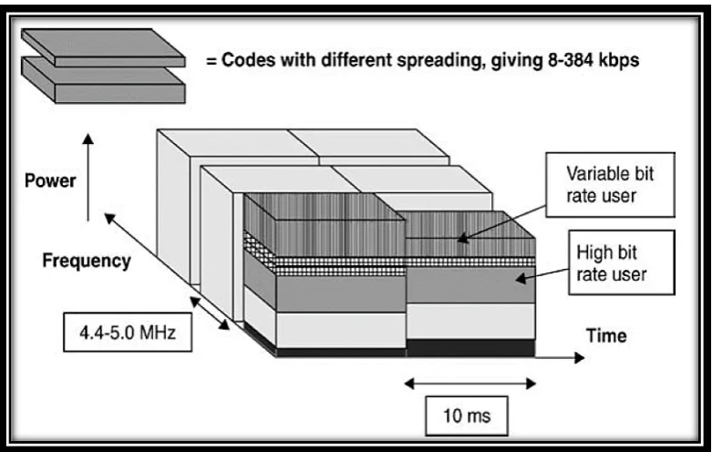
[image:26.595.113.530.413.640.2]In DS-SS each bit in the original signal is represented by multiple bits in the transmitted signal using spreading pseudo random code. Figure 2.2. shows the spreading and the de-spreading operation. The user's data is assumed to be Binary Phase Shift Keying (BPSK) modulated signal having bit rate Rb. Spreading is the X-NOR of each user bit with M chips (M=8) spreading code. Then, the transmitted signal should be 8 times more than the user data. At the receiver side, the received signal is X-NOR by the same spreading code used at the transmitter to detect the user's original data [5].
2.3.3 Processing Gain (Spreading Factor)
The ratio between the transmitted modulation bandwidth and the information signal bandwidth is called the Processing Gain (GP), as shown in equation (2.1) [9]:
Gp =
WR 2.1where W is the chip rate and R is the user data rate.
In WCDMA, the chip rate (w) is kept constant (3.84Mcbps) and thus the processing gain only depends on the user's data rate. The higher user's data rate gives lower processing gain. Thus, it is harder for the receiver to detect the signal correctly, due to the gain which added to the signal received at mobile is very low [10].
[image:27.595.105.533.460.547.2]Table 2.3 illustrates WCDMA data rate with processing gain.
Table 2.3: WCDMA Data Rate with Processing Gain [9]
User Data Rate (R) (kbps) Processing Gain (dB)
12.2 25
64 18
144 15
384 10
2.3.4 Scrambling
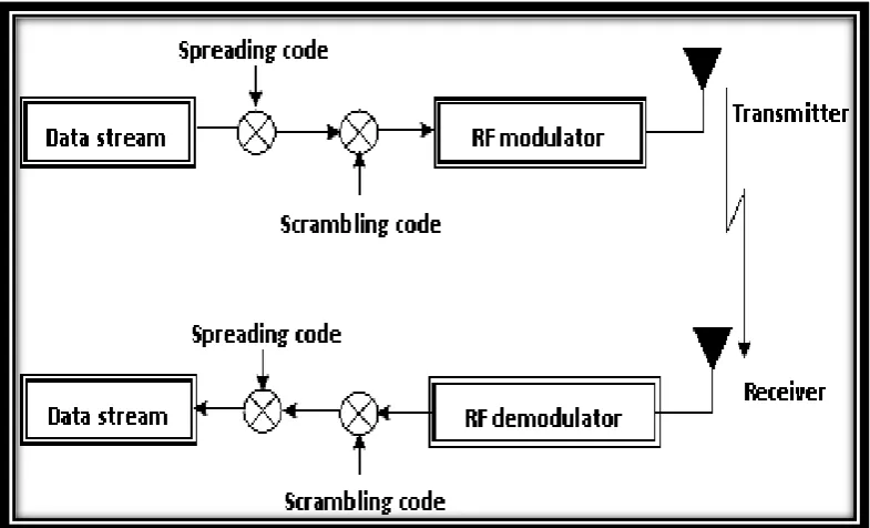
each other. Scrambling is done after spreading at the transmitter side and before de-spreading at the receiver as shown in Figure 2.3. [11].
Figure 2.3: Spreading and Scrambling Process
2.3.5 WCDMA System Codes
The task of each of channelization codes and scrambling codes varies in the uplink and the downlink [2].
[image:28.595.103.519.623.707.2]Table 2.4 illustrates WCDMA system codes and their applications.
Table 2.4: WCDMA system codes [2][5]
Code type Uplink Downlink
Scrambling Codes Users separation Cell separation
Channelization Codes Separation data and
control channels from the same UE
2.4 Multipath and RAKE Receiver
2.4.1 Multipath
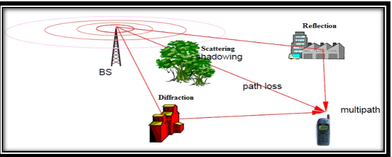
[image:29.595.119.508.364.520.2]Multipath is a phenomenon that happens in the channel of mobile systems when the transmitted signal arrives at the receiver via different paths due to reflection, diffraction and scattering resulting in fading. There is only one transmitted signal, due to obstacles like buildings, hills, trees, and so on, in the signal path that cause different signals to arrive at the receiver from various directions with different delays [7].Figure 2.4. illustrates three propagation components.
Figure 2.4: Propagation Component
where [12]:
• Path loss: decay of the signal strength with distance.
• Slow fading (Shadowing): is due to obstruction of the signal by natural
obstacles.
2.4.2 RAKE Receiver
In a multipath channel, the original transmitted signal is reflected by obstacles
before reaching the receiver and the receiver receives several copies of the original
signal with different delays. These multipath signals can be received and combined
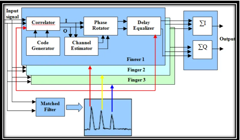
[image:30.595.113.513.480.714.2]using a RAKE receiver. The RAKE receiver consists of several sub-receivers known as correlators or fingers. RAKE receiver is a radio receiver designed to reduce the effect of multipath fading. Each correlator individually detects and processes one multipath component [3].Then, the outputs of the correlators are combined together using Maximal Ratio Combining (MRC) algorithm to gain reliable signal that leads to improve the system performance. Both BS and UE use RAKE receiver with the difference number of fingers (3 fingers in UE, while 4 or 5 fingers in BS) [13]. Figure 2.5. shows a RAKE receiver with three fingers, each finger is equipped with a correlator, channel estimator and phase rotator. The channel estimator tunes the amplitude according to certain attenuation factor and phase rotator equalizes the phases of fingers, before the signal from each finger is combined using certain
algorithm such as MRC [2].
2.5 Frequency Reuse
Frequency reuse is a parameter of how the same channels can be reused in neighboring cells.In WCDMA all users in the same cell share the same frequency spectrum simultaneously, while in 2G systems like GSM use a typical reuse pattern as 7 cells [4], as shown in Figure 2.6a. Cells of the same letters use the same channel frequencies. In WCDMA as illustrated in Figure 2.6b, it has the frequency reuse factor equal to one, this means that all the cells share the same duplex frequencies.
[image:31.595.113.515.373.584.2]Practically the frequency reuse factor (F) can be calculated in WCDMA system according to equation (2.2) [13]:
Figure 2.6: Frequency Reuse Factor [1]
a: Frequency reuse of 7. b: Frequency reuse of 1.
𝐹𝐹
=
1+1𝑖𝑖 2.22.6 Power Control and Handover in WCDMA
2.6.1 Power Control in WCDMA
In WCDMA system all users use the same duplex frequency at the same time. Hence the users will interfere with each other and could degrade the performance of the system. Therefore, itis important to control the transmit power. The power control feature ensures that both the user and control transmitted power levels are such that they cause minimum interference to other users in the system . The power control algorithm adjust the transmit power levels depending on the signal level and offered services [2].
There are three types of power control in WCDMA [6]:
1) Open-loop power control.
Open loop power control is performed in UE, UE examines the received power level measurements of Pilot signal to set its initial power level.
2) Closed-loop power control.
In closed loop power control, the transmitter of UE adjust the transmitted power in accordance with the transmit power control commands transmitted by BS to achieve a better Signal to Interference Ratio (SIR) nearest to given target SIR.
3) Outer-loop power control.
2.6.2 Handover in WCDMA
[image:33.595.113.517.323.469.2]One of the most important features of wireless cellular communication is the provision of mobility for the users. Therefore, each mobile user went entire a cell or network without the loss of connections its cell or network, this process is called handover. Handover is divided into two categories: hard and soft handover [5]. Both hard and soft handover schemes are supported in WCDMA. Hard handover (inter frequency handover) is used when the carrier frequency changes between the cells (for WCDMA 900MHz to WCDMA 2100MHz). In normal WCDMA operation, soft handover (SHO) is the most common handover scheme. In soft handover the mobile is connected simultaneously to two or more BS as shown in Figure 2.7. [5][6].
Figure 2.7: Soft handover between two cells
Besides SHO, it is also possible to maintain simultaneous connections to different sectors within the same serving BS sectored cell. This scheme is called softer
handover as shown in Figure 2.8. [6].
[image:33.595.114.519.615.777.2]2.7 Radio Access Network Architecture for WCDMA
In3GPP, the architecture of WCDMA system such as UMTS is divided into three major parts as illustrated in Figure 2.9. [5]:
1) User Equipment (UE).
2) UMTS Terrestrial Radio Access Network (UTRAN). 3) Core Network (CN).
[image:34.595.114.513.315.562.2]In UMTS the connection between mobile terminal and the core network is established by WCDMA Radio Access Network (RAN).
Figure 2.9: WCDMA Radio Access Network
• The UE consists of two parts :
1) The Mobile Equipment (ME) is the radio terminal used for radio communication.
• UTRAN consists of two parts:
1) The Node B converts the data between the Iub and Uu interfaces.
2) The Radio Network Controller (RNC), which may control one or more node Bs.
Note: the term ‘Node B’ from the corresponding 3GPP Specifications, the more generic term ‘Base Station’ means exactly the same thing [5].
The following main interfaces are shown in the Figure2.9. [5]:
• Cu interface: This is the electrical interface between the USIM smartcard and
the ME.
• Uu interface: This is the WCDMA radio interface, is the air interface between
UE and UTRAN.
• Iu interface: This connects the UTRAN and the CN.
• Iub interface: This is the air interface that connects a node B with the radio
network controller (RNC).
• Iur interface: This interface allows soft handover between RNCs from different
manufacturers and therefore, complements the open Iu interface.
2.8 Radio Network Planning
The target of the radio network planning in general is to provide maximum network coverage and system capacity together with sufficient quality for the planning area using reasonable implementation cost. There are three major radio system planning phases in WCDMA and are identified as [3][4]:
• Dimensioning.
Figure 2.10: Radio network planning process in WCDMA
2.8.1 Dimensioning
In the dimensioning phase, the main target is to obtain an estimation of the required radio network configuration and deployment strategy. The planner estimates the initial traffic requirements, the planning area, the initial coverage thresholds are needed, and theaverage antenna height must be defined in this phase in order to clarify the radio propagation channel characteristics in the next stage [2].
2.8.2 Detailed Planning
• Configuration planning :
Link budget (power budget) is the main tool in configuration planning phase. In the link budget calculations, for example gain of the antenna elements and the amplifiers, losses, and coverage thresholds are decided. The results of the link budget calculations is the uplink and the downlink maximum allowable propagation losses [15].
Table 2.5 illustrates an example of radio link budget for speech and data services.
• Topology planning :
Table 2.5: Example of a radio link budget for speech and data services [4][15].
(1)
Effective Isotropic Radiated Power (EIRP).
• Code, frequency and parameters planning :
The code planning phase in WCDMA is quite straightforward. Typically, in the frequency planning phase, the carrier usage for macro and micro cells is defined separately. Parameters planning include signalling parameter and Radio Resource Management (RRM) strategies, which contain power control,
Parameters Uplink Downlink Uplink Downlink symbol Units
Data rate 12.2 12.2 64 384 R kbps
Load 50 50 30 75 %
Thermal noise density
-174 -174 -174 -174 G dBm/
Hz Receiver noise
figure
4 8 4 8 F dB
Noise power at receiver
-104 -100 -104 -100 H=G+F+10log(3.84*106) dBm
Interference margin
3 3 2 6 I dB
Total noise power at receiver
-101 -97 -102 -94 J=I+H dBm
Processing gain 25 25 18 10 PG=10log(3.84*106/R) dB Eb/No required
[14]
5.1 7.4 1.7 3.4 L dB
Receiver sensitivity
-120.9 -114.5 -118.3 -100.6 M=L-PG+J dBm
RX
Rx antenna gain 18 0 18 0 N dBi
Body/cable loss 5 2 5 2 O dB
Soft handover diversity gain
2 3 2 3 S dB
Power control headroom
3 0 3 0 T dB
Required signal level
-132.9 -115.5 -130.3 -101.6 Req=M-N+O-S+T dBm
TX
TX power per connection
21 30 24 30 PPC dBm
Body/cable loss 2 5 2 5 OO dB
TX antenna gain 0 18 0 18 NN dBi
Peak EIRP (1) 19 43 22 43 EIRP=PPC-OO+NN dBm
Max propagation loss
151.9 158.5 152.3 144.6 Max L=EIRP-Req dB
[image:38.595.106.532.99.615.2]handover, and congestion control [14].
2.8.3 Optimisation
The optimisation phase is an adjustment process based on realistic changes that were not taken into account in the original radio system planning. Optimisation includes, for example verification of call, establishments and functionality of handover. Moreover, monitoring is also included in optimisation phase, since network performance is monitored, and parameters, like antenna tilt can be adjusted towards their optimum values [4][16].
2.9 Topology Planning
In WCDMA network coverage,the same carrier frequency is used over the radio network, and moreover other users signals are seen as additional interference. Hence, attention should be paid on coverage planning phases simultaneously in WCDMA radio network planning [16]. The name of coverage planning is topology planning. Topology planning defines the base station site configuration and location together with antenna configuration. The topology planning phase can be divided into:
2.9.1 Initial Topology Planning (Coverage)
In WCDMA network transmit power is shared between mobiles in downlink (one-to-multiple) and signal reception sensitivity depends on the interference level of a cell. Thus, in WCDMA networks, the coverage thresholds in a cell depend on the number of users and their bit rates. Therefore, the coverage thresholds have to be determined for each cell separately depending on the offered services. Figure 2.12. illustrates different cell coverage with different data rates [15][14].
[image:40.595.108.516.402.641.2]WCDMA network coverage can be roughly divided into two parts: common pilot channel (CPICH) and dedicated channel (DCH) coverage. CPICH is used for channel estimation, handover measurements and cell selection/reselection procedures (define cell border). Typically 5 - 10% of the total base station power is reserved for CPICH. DCH is used for transfer data rate to the user [4][17].
2.9.2 Detailed Topology Planning
In the detailed topology planning phase, the network parameters and configurations of the initial topology planning phase are moved into the Radio Network Planning (RNP) tool or simulator. RNP tool for WCDMA radio network planning must to have at least the following properties [14]:
- User interface for controlling the data. - Possibility to utilize digital maps. - Site and antenna configuration editors. - Propagation model editor.
- Coverage predictions. - Traffic modeling.
- Capacity and performance simulator.
![Table 2.1: Evaluation of Mobile Communication Systems [1]](https://thumb-us.123doks.com/thumbv2/123dok_us/8759427.893631/22.595.108.518.125.229/table-evaluation-mobile-communication-systems.webp)
![Table 2.2: The Main Parameters of WCDMA System [5]](https://thumb-us.123doks.com/thumbv2/123dok_us/8759427.893631/23.595.106.518.98.255/table-main-parameters-wcdma.webp)
![Figure 2.2: Spreading and the De-spreading Operation [4]](https://thumb-us.123doks.com/thumbv2/123dok_us/8759427.893631/26.595.113.530.413.640/figure-spreading-spreading-operation.webp)
![Table 2.3: WCDMA Data Rate with Processing Gain [9]](https://thumb-us.123doks.com/thumbv2/123dok_us/8759427.893631/27.595.105.533.460.547/table-wcdma-data-rate-processing-gain.webp)
![Figure 2.6: Frequency Reuse Factor [1]](https://thumb-us.123doks.com/thumbv2/123dok_us/8759427.893631/31.595.113.515.373.584/figure-frequency-reuse-factor.webp)