International Journal of Emerging Technology and Advanced Engineering
Website: www.ijetae.com (ISSN 2250-2459, Volume 2, Issue 4, April 2012)418
Suggested Modifications of the Conventional Rigid Method for
Mat Foundation Design
S. Shihada
1, J. Hamad
2and M. Alshorafa
3 1Professor, Civil Engr. Dept, IUG-Gaza
2Assistant Professor, Civil Engr. Dept, IUG-Gaza- Corresponding Author: 3M.Sc in Structural Engineering
1[email protected] 2[email protected] 3
Abstract:- The conventional rigid method for mat foundation design is characterized by its ease in execution and therefore, suitable for hand calculations and for small-size mats. Nevertheless, the method is impeded by its inability to satisfy the equations of static equilibrium, which makes the evaluation of correct shear forces and bending moments rather impossible. This study aims at satisfying the equilibrium equations, by suggesting three modification procedures of the conventional rigid method, in order to construct correct shear force and bending moment diagrams. Based on the results of this study, it is found that the three proposed modification approaches constitute lower-bound, average and upper-bound solutions to the internal forces, with maximum differences between upper and lower-bound solutions not exceeding 16 %.
Keywords:- Mat; Shear; Moment; Rigid; Modification Factor; Conventional
I. INTRODUCTION
The structural design of reinforced concrete mat foundations has been for many years one of the least satisfactory areas of design [1].
Mats may be designed and analyzed as either rigid bodies or as flexible plates supported by an elastic foundation. An exact theoretical design of a mat on elastic foundation can be made; however a number of factors reduce the exactness to a combination of approximations. These include difficulty in predicting subgrade responses, variations in soil properties, mat shape, variety of superstructure loads and effect of superstructure stiffness on mat. The analysis and design is carried out using any of the following methods [2]:
Conventional Rigid Method,
Approximate Flexible Method,
Finite Difference Method and
Finite Element Method.
For rigid mat design using the conventional rigid method, two approaches have been suggested; the inverted floor system and the combined footing approach [3].
Teng [4] describes the conventional rigid method, where the pressure under the mat follows a planar distribution such that the centroid of the bearing pressure coincides with the line of action of the resultant force of all column loads acting on the mat. Then, the mat is analyzed as a whole in each of the two perpendicular directions and the total shear forces and bending moments at any section cutting across the mat is equal to the arithmetic sum of all forces and reactions on the left, or right, of this section. The stress distribution along this section is a problem of a highly indeterminate nature.
ACI committee 3362R [2] suggests that mats may be designed and analyzed as either rigid bodies or as flexible plates supported by elastic foundation. In case column spacing is less than 1.75 divided by
or the mat is very thick and variation of column loads and spacing is not over 20%, mat may be designed by treating it as a rigid body and considering strips both ways. These strips are analyzed as combined footings with multiple column loads and loaded with the soil pressure on the strip and column reactions equal to loads obtained from the superstructure analysis. Since a mat transfers load horizontally, any given strip may not satisfy vertical load summation.The effect of column spacing on the behavior of a five story building is studied by Naratajan and Videivelli [5], where they conclude that column spacing has a marginal effect on the contact pressure. Moreover, they state that the increase in mat thickness results in reduced settlement increased bending moments and reduced uniform pressure. Bowels [6] states that the mats may be designed as rigid structures where the mat is sub-divided into a series of continuous beams (strips) centered on the appropriate column lines.
International Journal of Emerging Technology and Advanced Engineering
Website: www.ijetae.com (ISSN 2250-2459, Volume 2, Issue 4, April 2012)419
The portion between beams is designed as a conventional one or two way slabs. Furthermore, Bowels [7] requires that the strip loads need to be adjusted so that statics is satisfied since the shear between adjacent strips is not included in the strip free body. For column loads not falling at the center of the strip area, a nonlinear soil pressure diagram is to be used to close the shear and moment diagrams. Later on, it is affirmed that the method is not recommended at present because of the substantial amount of approximations and the wide availability of computer programs that are relatively easy to use [8, 9].
Das [10] presents the conventional rigid method using strips between column lines in both directions. He proposes a method for satisfying static equilibrium of forces resulting from ignoring shear between adjacent strips. This is done through two sets of modification factors, one for column loads and the other for soil pressures at both ends of each of the individual strips. The soil pressure under each strip is taken as the average of the two values at the end of each strip. Furthermore Das [11] proposes that the soil pressure is not to be averaged at the bottom of each strip while adopting the same modification procedure described in Das [10].
II. IMPORTANCE OF MODIFIED/PROPOSED CONVENTIONAL RIGID METHOD
The conventional rigid method is characterized by its simplicity and ease in execution. On the other hand, the resultant of column loads doesn't coincide with the resultant of soil pressure under the individual strips, which leads to violation of the static equilibrium equations. Most prestigious foundation design textbooks shy away from this fact either by selecting symmetrically-loaded strips and using uniform soil pressure to reduce the eccentricity to zero, or by drawing mistaken shear force and bending moment diagrams that do not close [7, 9, 10, 11]. Others analyzed the mat as a whole in each of the two perpendicular directions and evaluated the shears and moments along selected sections [4]. The stress distribution along this section is a problem of a high indeterminacy.
In this work, the conventional rigid method, using the strip method, is to be modified using three different approaches that satisfy the equilibrium of forces in the vertical direction as well as the summation of moments at any point along the considered strip. Consequently, correct shear force and bending moment diagrams can be achieved.
III. THE CONVENTIONAL RIGID METHOD-CASE STUDY
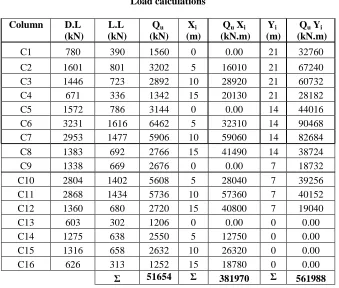
[image:2.612.361.545.306.558.2]A case-study of mat foundation design is worked out using the conventional rigid method as described in Das [10] to show its shortcomings. See Figure-1 and Table-1 for dimensions and loading. Note that ACI 318-08 load factors are followed [12].
International Journal of Emerging Technology and Advanced Engineering
Website: www.ijetae.com (ISSN 2250-2459, Volume 2, Issue 4, April 2012)420
C8 1383 692 2766 15 41490 14 38724
C9 1338 669 2676 0 0.00 7 18732
C10 2804 1402 5608 5 28040 7 39256
C11 2868 1434 5736 10 57360 7 40152
C12 1360 680 2720 15 40800 7 19040
C13 603 302 1206 0 0.00 0 0.00
C14 1275 638 2550 5 12750 0 0.00
C15 1316 658 2632 10 26320 0 0.00
C16 626 313 1252 15 18780 0 0.00
Σ 51654 Σ 381970 Σ 561988
Step 1: Evaluate the factored net soil pressure under the mat
The eccentricity ex is given as
m 105 . 0 5 . 7 51654 381970
ex
The eccentricity ey is given as
m 38 . 0 5 . 10 51654 561988
ey
14985.9 y 9621 1 7645.9
x ) 54350 (
4 . 358
1654 , 5 qu,net
y 1 . 13 x ) 1 . 7 ( 1 .
144
Step 2- Draw shear and bending moment diagrams
The mat is divided into four strips in the first perpendicular direction and another four in the second direction. Strip BDKM which is 22.4 m long and 5 m wide is considered here for demonstrable purposes.
2 C 160.57 kN/m
q
2 L 131.24 kN/m
q
The average uniform soil pressure is given by
2 avg
,
u 145.9kN/m
2 24 . 131 57 . 160
q
Total soil reaction = 145.9 (22.4) (5) = 16340.8 kN Total column loads = 17822 kN
= 17081.6 kN
2
5 . 17822 8
. 16340 load
Average
Column modification factor = 0.958 0
. 17822 6 .
17081
Soil pressure modification factor = 1.045 9
. 16340
6 . 17081
Average modified soil pressures are 167.8 kN/m2 and 137.2 kN/m2 at points C and L respectively.
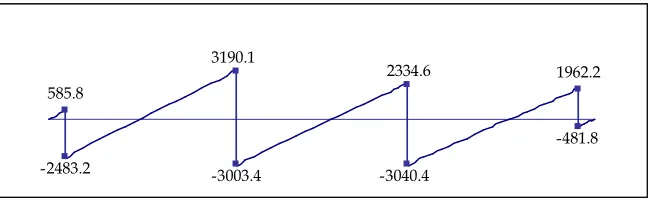
[image:3.612.138.477.180.468.2]Shear force and bending moment diagrams for strip BDKM are shown in Figures-2 and 3.
Table 1 Load calculations
Column D.L
(kN)
L.L (kN)
Qu (kN)
Xi (m)
Qu Xi (kN.m)
Yi (m)
Qu Yi (kN.m)
C1 780 390 1560 0 0.00 21 32760
C2 1601 801 3202 5 16010 21 67240
C3 1446 723 2892 10 28920 21 60732
C4 671 336 1342 15 20130 21 28182
C5 1572 786 3144 0 0.00 14 44016
C6 3231 1616 6462 5 32310 14 90468
International Journal of Emerging Technology and Advanced Engineering
Website: www.ijetae.com (ISSN 2250-2459, Volume 2, Issue 4, April 2012) [image:4.612.144.471.137.238.2]421
Figure 2 Shear force diagram for strip BDKM (kN)
Figure 3 Bending moment diagram for strip BDKM (kN.m)
It is noticed that while the shear force diagram satisfies the equilibrium of forces in the vertical direction, the bending moment diagram fails to do so, yielding a bending moment of 3016.9 kN.m at the end of the strip, instead of zero.
IV. PROPOSED MODIFICATIONS OF THE CONVENTIONAL RIGID METHOD:
In this section three proposed modifications are applied to the conventional rigid method and shear and bending moment diagrams are drawn for strip BDKM.
A. First proposed modification:
In this proposed modification, the strip shown in Figure-4 is treated as a combined footing with the planar soil distribution evaluated for the entire mat being ignored. Therefore, a new soil pressure under mat ends is evaluated based on the strip columns loads from the following equation.
y x u u ) new (I B/2 e Q A
Q
q1,2 (1)
Figure 4 Strip loads- First proposed modification
Using the above equation, the resultants of the soil pressure under the strip and the resultant of the columns loads will have the same line of action. Then, shear force and bending moment diagrams can be easily constructed. Modified loads acting on strip BDKM are shown in Figure-5.
Qu 320264625608250517822KN
m 65 . 10 17822
) 7 . 21 ( 2550 ) 7 . 14 ( 5608 ) 7 . 7 ( 6462 ) 7 . 0 ( 3202
Xl
m 55 . 0 65 . 10 2
4 . 22
ex
2m 112 5 4 . 22
A
-2483.2 -3003.4 -3040.4
2334.6 3190.1
585.8
1962.2
-481.8
-3520.3 -2924.6 -5610.0
-2848.5 -3016.9
205.2
2875.0
International Journal of Emerging Technology and Advanced Engineering
Website: www.ijetae.com (ISSN 2250-2459, Volume 2, Issue 4, April 2012)422
3 4m 1 . 4683 12
4 . 22 5
I
2
1 182.56 kN/m
46831
) 5 . 0 )( 4 . 22 )( 55 . 0 ( 17822 112
17822
q
2
2 135.68 kN/m
46831
) 5 . 0 )( 4 . 22 )( 55 . 0 ( 17822 112
17822
q
The modified soil pressure and column loads for strip
[image:5.612.336.559.143.207.2]BDKM are shown in Figure-5. Figure 5 Loads acting on strip BDKM- First proposed modification Figures 6 and 7 show the shear and bending moment diagrams, respectively for strip BDKM. One can easily observe that the equilibrium equations are satisfied for shear as well as for bending moment.
Figure 6 Shear force diagram for strip BDKM- First proposed modification
[image:5.612.147.468.309.387.2](kN)
Figure 7 Moment diagram for strip BDKM- First proposed modification (kN.m)
B. Second proposed modification:
This includes modifying the columns loads on the strip only through modification factors for columns loads based on the planar soil pressure under the entire mat. Two modification factors are employed in order to make the resultant of the modified column loads coincide with the resultant of the soil pressure under the strip. Column loads situated to the left of the resultant are multiplied by a modifying factor F1 and column loads situated to the right of the resultant are multiplied by a second modifying factor F2 as follows.
Application of the mentioned process on strip BDKM, shown in Figure-8 is outlined next.
Equation (2) is evaluated through application of static equilibrium of forces in the vertical direction.
B B q q Q
F Q
F Left Right i
( ) ) 1 2 22
1 )2)
Equation (3) is evaluated through application of static
equilibrium on summation of
moments.
2 1
1 2 2
1
2 1
3
2
2
)
)
(
q
q
B
q
q
B
B
q
q
Q
F
x
Q
F
i
x Right i
Left i
(3)
2626
-2982 3518.6
-2943.4 -2565.3
636.7
2072.8
-477.2
-3449.9
-1424.5 -2921
3048.8 3859.8
[image:5.612.148.468.454.534.2]International Journal of Emerging Technology and Advanced Engineering
Website: www.ijetae.com (ISSN 2250-2459, Volume 2, Issue 4, April 2012)423
[image:6.612.49.250.149.223.2]
Figure 8 Strip Loads- Second proposed modification
Solving Equations (2) and (3), the values of F1 and F2 can be easily obtained. Therefore, the shear force and bending moment diagrams can be constructed.
The column loads on the strip and soil pressure under strip BDKM are shown in Figure-9.
Substituting in Eqn. (2), one gets
5)(22.4)
(
2
2
.
131
6
.
160
2550
5608
6462
3202
21
F
F
kN
163409
F
8158
F
9664
1
2
Substituting in Eqn. (3),
)
2
.
131
6
.
160
(
3
4
.
22
6
.
160
)
2
.
131
(
2
9
.
16340
))
7
.
21
(
2550
)
7
.
14
(
5608
(
))
7
.
7
(
6462
)
7
.
0
(
3202
(
21
F
F
7
.
189164
6
.
137772
8
.
51998
F
1
F
2
Solving equations (2-a) and (3-a) gives F1 = 0.891 and F2 = 0.948.
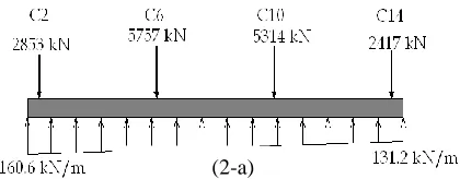
The modified column loads are as follows: Q1 mod = F1 Q1 = 0.891(3202) = 2853 kN Q2 mod = F1 Q2 = 0.891(6462) = 5757 kN Q3 mod = F2 Q3 = 0.948(5608) = 5314 kN Q4 mod = F2 Q4 = 0.948(2550) = 2417 kN
[image:6.612.327.537.284.366.2]The soil pressure and modified column loads for strip BDKM are shown in Figure-9.
Figure 9 Loads on strip BDKM based on the second proposed modification
[image:6.612.149.464.485.612.2]Figures 10 and 11 show the shear and bending moment diagrams respectively for strip BDKM. One can easily see that the equilibrium equations are satisfied for shear force, as well as for bending moment.
Figure 10 Shear force diagram for strip BDKM - Second proposed modification (kN)
-2830.2 2484.1
-2622.4 3134.9
-2292.4
560.4 1955.5
-460.9
(2-a)
International Journal of Emerging Technology and Advanced Engineering
Website: www.ijetae.com (ISSN 2250-2459, Volume 2, Issue 4, April 2012) [image:7.612.147.468.136.238.2]424
Figure 11 Moment diagram for strip BDKM - Second proposed modification (kN.m)
C. Third proposed modification:
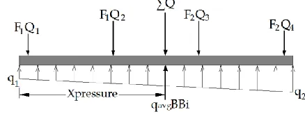
This proposed modification involves both of the columns loads on the strip and the applied soil pressure under the mat. The strip is modified by finding the average loads required to make the resultant of column loads equal to and coincide with that of the average loads at mid point between the influence points of column loads and soil reaction. Two sets of modifying factors are applied to make the resultant of the modified column load equal and coincide with that of the average loads. The first factor will be applied to column loads on the left side of the resultant of the modified column loads, while the second factor will be applied to column loads on the right side of the resultant. Then, the shear force and bending moment diagrams can then be constructed.
The loads acting on the strip are shown in Figure-12 and the process is detailed as follows.
Figure 12 Loads on strip BDKM before application of the third proposed modification
Solving Equations (2-a) and (3-a), gives F1 and F2 values.
The modified soil pressure and column modified loads for strip BDKM are shown in Figures-13 and 14.
Figure13 Modified loads on strip BDKM-Third proposed modification
Q 17822 kN
Qtotal i
kN
B
B
q
reaction
Soil
avg i9
.
16340
4
.
22
*
5
*
2
2
.
131
6
.
160
)
(
kN 5 . 17081 2
17822 9
. 16340 load
Average
,
m
82
.
10
x
and
m
65
.
10
x
L
p
m 74 . 10 2
82 . 10 65 . 10 x
,
so average
Substituting in Equations (2) and (3) gives F1 = 0.945 and F2 = 0.975.
The modified column loads are as follows: Q1 mod = F1 Q1 = 0.945*3202 = 3026 kN Q2 mod = F1 Q2 = 0.945*6462 = 6106 kN Q3 mod = F2 Q3 = 0.975*5608 = 5465 kN Q4 mod = F2 Q4 = 0.975*2550 = 2485 kN
And ; ,mod 2
2 133.6 kN/m
q
2 mod
,
1 171.4 kN/m
q
-3121.7
-1285.1
-2704.9
3035.3 3332.1
[image:7.612.69.288.477.559.2]International Journal of Emerging Technology and Advanced Engineering
Website: www.ijetae.com (ISSN 2250-2459, Volume 2, Issue 4, April 2012)425
Figure 14. Applied load on the strip BDKM- Third proposedmodification
Figure 15 and 16 show the shear and bending moment diagrams respectively for strip BDK M. One can easily notice that equilibrium equations are satisfied for shear as well as for bending mo ment
[image:8.612.99.477.128.504.2].
Figure 15 Shear force diagram for strip B D K M - Third proposed modification (kN)
Figure 16 Moment diagram for strip B D K M - Third proposed modification (kN.m)
V. DISCUSSION OF THE RESULTS
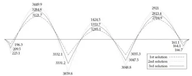
[image:8.612.150.465.400.501.2]From the results obtained from the three modification procedures it is noticed that the first modification procedure represents an upper bound solution of the results, while the second procedure represents a lower bound solution. Moreover, the third proposed modification procedure represents an average solution of the first and second proposed modification procedures. The bending moments obtained from the three procedures are shown in Figure-17. The differences in bending moments are shown in Table-2, where the differences for the upper-bound solution obtained from the first proposed modification procedure range from 0.44 % to 15.84 % compared with the lower-bound solution obtained from the second modification procedure. Similarly, the average solution obtained from the third proposed modification procedure
ranges from 0.40 % to 7.78 % compared with the lower-bound solution.
Figure 17 Bending moments obtained from the three modification procedures for BDKM (kN.m)
2556.8
-2908.3 3324.7
-2781.2 -2427.5
598
2015.4
-469.6
-3284.8
-1353.7 -2813.4
164.1
3591.2 3047.5
[image:8.612.344.542.588.667.2]International Journal of Emerging Technology and Advanced Engineering
Website: www.ijetae.com (ISSN 2250-2459, Volume 2, Issue 4, April 2012)426
Table 2
Bending moments for Strip BDKM and percentages of differences among the three solutions
Exterio r Span (t.m) Interior Span (t.m)
Exterior Span (t.m) Procedure Ext. + ve Ext. - ve Inte rior + ve Inte rior - ve Inte rior + ve Inter ior - ve Exte rior + ve 16.67 3.48% 292. 10 7.99 % 304. 88 0.44 % 142. 45 10.8 5% 385. 98 15.8 4% 344.9 9 10.51 % 22.3 1 13.6 5% 1st Proced ure 16.11 0% 270. 49 0% 303. 53 0% 128. 51 0% 333. 21 0% 312.1 7 0% 19.6 3 0% 2nd Proced ure 16.41 1.86% 281. 34 4.01 % 304. 75 0.40 % 135. 37 5.34 % 359. 12 7.78 % 328.4 8 5.22 % 20.9 5 6.72 % 3rd Proced ure
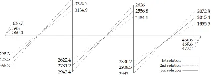
[image:9.612.64.276.472.550.2]Figure 18 shows the shear forces obtained from the three modification procedures. The differences in shear forces are shown in Table 3, where the differences for the upper-bound solution obtained from the first proposed modification procedure ranges from 3.54 % to 13.61 % compared with the lower-bound solution obtained from the second modification procedure. Similarly, the average solution obtained from the third proposed modification procedure range from 1.89 % to 6.71 % compared with the lower-bound solution.
Figure 18 Shear forces obtained from the three modification procedures for BDKM (kN)
Table-3
Shear forces for Strip BDKM and percentages of differences among the three solutions (kN)
Column No. 14 Column No. 10 Column No. 6 Column No. 2 Proce dure Rig ht Left Rig ht Left Rig ht Left Rig ht Left 47.7 2 3.54 % 207. 28 5.99 % 298. 2 5.36 % 262. 6 5.71 % 294. 34 12.2 4% 351. 86 12.2 4% 256. 53 11.9 0% 63.6 7 13.6 1% 1st Proce dure 46.0 9 0% 195. 55 0% 283. 02 0% 248. 41 0% 262. 24 0% 313. 49 0% 229. 24 0% 56.0 4 0% 2nd Proce dure 46.9 6 1.89 % 201. 54 3.06 % 290. 83 2.76 % 255. 68 2.93 % 278. 12 6.05 % 332. 47 6.05 % 242. 75 5.89 % 59.8 0 6.71 % 3rd Proce dure
VI. CONCLUSIONS
The three modification procedures suggested by the authors for mat foundation design have succeeded in solving the main problem associated with the conventional rigid method, which is satisfaction of the equilibrium equations when constructing shear force and bending moment diagrams for the individual strips for the mat.
The three obtained solutions represent lower bound, average and upper bound solution for shear forces and bending moments for each individual strip of the mat.
Since two-way action is ignored in analyzing the strips, it is recommended that the lower bound solution associated with modifying column loads only be used in evaluating shear forces and bending moments in the strips.
The maximum differences in bending moments obtained from the three procedures is less than 16 %.
International Journal of Emerging Technology and Advanced Engineering
Website: www.ijetae.com (ISSN 2250-2459, Volume 2, Issue 4, April 2012)427
REFERENCES
[1 ] Eden, W., McRostie, G., Hall, J., 1973- Measured Contact Pressures Below Raft Supporting A stiff Building, Canadian Geotechnical Journal, Vol. 10, pp. 180-192.
[2 ] American Concrete Institute (ACI) Committee 3362R, Suggested Design Procedures for Combined Footing and Mats (ACI 336.2R-88, Reapproved 2002), Detroit, Michigan, USA, 2002.
[3 ] Gupta, S., Mat Foundations Design and Analysis with a Practical Approach, New Age International limited Publishers, New Delhi, 1997.
[4 ] Teng, W., Foundation Design, Prentice Hall, Prentice Hall Inc., Englewood Cliffs, 1962.
[5 ] Natarajan, K., Vidivelli, B., 2009- Effect of Column Spacing on the Behavior of Frame-Raft and Soil Systems, Journal of Applied Sciences, Vol. 9, No. 20, pp. 3629-3640.
[6 ] Bowles, J., Foundation Analysis and Design, 2nd ed., McGraw-Hill Book Co., New York, USA, 1997. [7 ] Bowles, J., Foundation Analysis and Design, 3rd ed.,
McGraw-Hill Book Co., New York, USA, 1982. [8 ] Bowles, J., Foundation Analysis and Design, 4th ed.,
McGraw-Hill Book Co., New York, USA, 1996. [9 ] Bowles, J., Foundation Analysis and Design, 5th ed.,
McGraw-Hill, International Edition, 1997.
[10 ] Das, B., Principles of Foundation Engineering, PWS Engineering, Boston, Massachusetts, USA, 1984 [11 ] Das, B., Principles of Foundation Engineering, 4th
ed., PWS Engineering, Boston, Massachusetts, USA, 1999..
[12 ] American Concrete Institute (ACI). 2008. Building Code Requirements for Structural Concrete (318-08) and Commentary (318 R-08), Farmington Hills, Michigan, USA, 2008.
NOTATION
A = total area of the mat
B = length of mat strip
Bi = width of mat strip between centers of adjacent strips
D.L= Column's service dead load
L.L = Column's service live load
y x,e
e = coordinates of the resultant force relative to the
center of area of the mat
Ec = modulus of elasticity of concrete
1
F = modification factor for column loads located to the left of the resultant
2
F = modification factor for column loads located to
the right of the
I = moment of inertia of the strip of width Bi
y x,I
I = moment of inertia of the area of the mat with
respect to the
x
andu
Q = factored column loads
Qleft = summation of column loads located to the left of the resultant
right Q
= summation of column loads located to the right of the resultant
mod , total
Q = modified column loads
mod , avg
q = modified average soil pressure
i
X = coordinate of column load in x-direction, relative to the point of origin
i
Y = coordinate of column load in y-direction, relative to the point of origin
y ,
x = coordinate of any given point on the mat with respect to
x
andy
axes passing through the centroid of the matxl = the distance between Qtotal and the left edge of the mat strip
xp = the distance between the resultant of average soil pressure and the left edge of mat strip
2 x x xaverage l p
net , u
q = factored net soil pressure
avg , u
q = average factored net soil pressure resultant
= characteristic coefficient = 4 ci s
I E 4
B K
s
International Journal of Emerging Technology and Advanced Engineering
Website: www.ijetae.com (ISSN 2250-2459, Volume 2, Issue 4, April 2012)428
Samir Shihada is professor in structural engineering at the department of civil engineering in the Islamic University of Gaza. He has extensive experience in teaching and practicing structural concrete design where he has published a refereed book entitled “Reinforced Concrete Design”. His research interests include structural concrete design codes, seismic design and fire-resistant concrete. Furthermore, he has served on several government committees dealing with building damage evaluation and engineering education.
Jehad T. Hamad has a Ph.D. in the field of Geotechnical/Geoenvironmental Engineering - Louisiana State University - December 1990. He worked at Southern Illinois University and Bir-ziet University. Currently, He is a member of the Civil Engineering department at the Islamic University-Faculty of Engineering. He worked as a consultant engineer in a number of private and public engineering firms in USA and Gaza Strip in the field of Geotechnical/Geoenvironment Engineering.