© 2017, IRJET | Impact Factor value: 5.181 | ISO 9001:2008 Certified Journal | Page 1725
Mitigation of Voltage and Current Harmonics Using UPQC Base On
Synchronous Reference Frame Method
Anu Yadav
1, Parveen Kumar
21
PG Student, Dept of EE, Mata Raj Kaur Institute of Engineering & Technology, Saharanwas, Rewari, India
2Associate Professor & HOD
, Dept of EE, Mata Raj Kaur Institute of Engineering & Technology, Saharanwas,
Rewari, India
---***---ABSTRACT: This paper presents a three -phase active power filter for harmonic compensation which is consists of a series active power filter and a shunt passive filter. The active filter connected in series to a source acts as a harmonic isolator between the sources and loads whereas the shunt passive filter is connected in parallel with a load and suppresses the harmonic current produced by the load. Matlab /Simulink and are used for simulation. From the simulation results it is confirmed that the filter topology is capable of compensating the load current and voltage harmonic distortion within the stipulated limits laid down by the IEEE 519 standard.
KEYWORDS: Shunt active power filter, series active power filter, voltage harmonics, current harmonics, UPQC.
I. INTRODUCTION
Power-electronics circuits are widely used in industrial equipment, such as frequency changers, motor-drive systems (AC voltage controller, chopper), etc. Such equipment presents nonlinear impedance to the utility, generating large harmonic currents and voltages with well-known adverse effects, such as low power factor, low efficiency and destruction of other equipment. Also, some precision instruments and communication equipment will be interfered with the EMI.
The effects of current harmonic distortion are poor utilization of distribution wiring and plant, increased power loss, high current flow in the neutral line and dangerous cable overheating. Voltage harmonic interrupts the proper operation of digital electronics mainly communications and process control, which needs sinusoidal supply voltage. Harmonic problem may result in mal-operation of protection equipment, which does not; itself draw harmonic currents from the supply.
Active filters, different from the passive filter, have the capability of dynamically adjusting to the conditions of the system in terms of harmonics and reactive power compensation. The effectiveness of Active Power Filter
depends on the requirements, inverter type and topology. On the basis of topology Active Power Filter can be classified as series connected Active Power Filter and Shunt connected Active Power Filter. Series connected Active Power Filter can be connect before the load in series with the mains using a matching transformer to eliminate the voltage harmonics and to balance and regulate the terminal voltage of the load. Also it can be used to regulate the negative sequence voltage at the load. So the series Active Power Filter works as a controllable voltage source. The drawbacks of this series connected Active Power Filter is, it only compensates the voltage harmonics and another problem is for the short circuit in the load end. This short circuit current passes through the series transformer winding, which may overload the series transformer.
II. SYSTEM CONFIGURATION
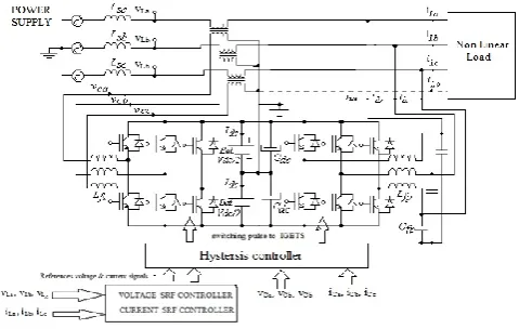
[image:1.595.315.555.557.709.2]The proposed topology consists of a series and shunt active power filter. The active filter connected in series to a source acts as a harmonic isolator between the source and load whereas the shunt active filter is connected in parallel with a load and suppresses the harmonic current produced by the load as shown in Figure 1.
Figure 1 system configuration
© 2017, IRJET | Impact Factor value: 5.181 | ISO 9001:2008 Certified Journal | Page 1726 shunt active filter compensates the harmonic current by
using synchronous reference frame (SRF) -based controllers. The three-Phase PLL used for generation of the unit vector coordinates (sinθ and cosθ) used in the SRF-based algorithms. The SRF-based controller was used to generate the sinusoidal compensating current and voltage references applied to a three-phase line-interactive UPS System.
III.CURRENT AND VOLTAGE HARMONIC DETECTION
In this paper this synchronous reference frame (SRF) method is used to generate the reference voltage and current required to compensate the voltage and current harmonics. The three voltage and/or current signals in a-b-c coordinates are transformed to the orthogonal α-β stationary frame using (1) and then to synchronous rotating frame (d-q) using (2). Based on the control needs the required components are extracted/ separated in d-q frame. To generate the reference signals and thus, to transform them back to original frame, the inverse transformation from d-q to α-β frame, and then to a-b-c frameis carried out utilizing (3) and (4), respectively.
i. Clark’s Transformation
It transforms sensed source voltage /current signal from a-b-c stationary to α-β stationary coordinate system by following equation
12 1 2 1 2 1 2 3 2 3 0 2 1 2 1 1 3 2 cc cb ca o x x x x x x
ii. Park’s Transformation
Now this signal α-β is converted in d-q frame by using equation
2
cos
sin
sin
cos
x
x
t
t
t
t
x
x
q diii. Reverse Park’s Transformation (α-β to d-q)
3
cos
sin
sin
cos
q dx
x
t
t
t
t
x
x
iv. Reverse Clark’s Transformation (d-q to a-b-c)
x
x
x
x
x
x
c b a.
2
1
2
3
2
1
2
1
2
3
2
1
2
1
0
1
.
3
2
Where x represents the variable under consideration, and can be voltage or current.
A.Current SRF controller
In this method the measured load currents are transformed into the rotating reference frame (d-q frame) that is synchronously rotating at the line voltage frequency using (1) and (2).The line frequency components of the load currents become DC quantities and the harmonic components are frequency shifted by ωt in the d-q reference frame. A high pass filter in the d-q frame, with a cut-off at the line frequency can be used to extract the DC components. Currents to transform them back to original frame, the inverse transformation from d-q to α-β frame, and then to a-b-c frame is carried out utilizing (3) and (4).Reference compensating currents(ica*,icb*,icc*) generated using current SRF controller which shown in figure 2
B. Voltage SRF controller
© 2017, IRJET | Impact Factor value: 5.181 | ISO 9001:2008 Certified Journal | Page 1727 Figure 2 current and voltage harmonic detection
IV.HYSTERESIS CURRENT CONTROLLER
Hysteresis current control method of generating the switching signal for the inverter switches in order to control the inverter output current [5]. It is adopted in active filter due to best among other current control methods, easy implementation and quick current controllability.[4] It is basically a fed back current control method, where the actual current continuously tracks the reference current in the hysteresis band(Figure 4).The actual current with in this hysteresis band. The reference and actual current or voltage is compared with respect to hysteresis band which decides switching pulse of voltage source inverter.
Figure 3.Hysteresis Controller
As the current crosses a set hysteresis band, the upper switch in the half-bridge is turned off and the lower switch is turned on (Figure 5). As the current exceeds the lower band limit, the upper switch is turned on and the lowers witch is turned off.
[image:3.595.318.550.169.352.2]The switching frequency depends on how fast the current changes from upper limit to lower limit and vice versa. This, in turn depends on voltage vd and load inductance.
Figure 5.Hysteresis Band and Generation of Pulses
V.SIMULATION RESULTS
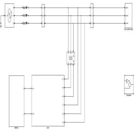
The proposed model for a shunt series active power filter using harmonic detection method with hysteresis current controller has been successfully modelled and tested using MATLAB/SIMULINK toolbox.
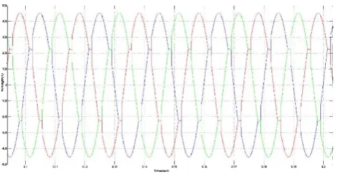
[image:3.595.320.539.486.699.2] [image:3.595.56.271.552.638.2]© 2017, IRJET | Impact Factor value: 5.181 | ISO 9001:2008 Certified Journal | Page 1728 Figure 6.Distorted current at source without
compensation
[image:4.595.44.279.263.379.2]Figure 7. FFT analysis for above distorted current wave forms
[image:4.595.312.554.454.579.2]Figure 8 shows FFT analysis for figure 7wave from and distorted current THD is 21.7%.
Figure 8.Distorted voltages at source without compensation
Figure 9. FFT analysis for above distorted voltages wave form distorted voltage THD is 7.9 %.
Figure 10.Current at source after compensation
[image:4.595.48.276.465.577.2]Figure 11. FFT analysis for above currents wave form and distorted current THD is 1.89%.
[image:4.595.318.552.612.719.2]Figure 12.voltages at source after compensation
[image:4.595.55.267.624.723.2]© 2017, IRJET | Impact Factor value: 5.181 | ISO 9001:2008 Certified Journal | Page 1729
Results
Parameters Without compensation
With compensation
voltage
(THD-V) % 7.9 3.4
current
(THD-I) % 21.7 1.89
VI. CONCLUSION
This project presents some insight about the active power flow in an electrical system with a three Phase Series and shunt Active power filter. The presented three -Phase Series and shunt Active power filter makes use of two back-to-back converters with different purposes and distinct coupling with the electrical power system. One is shunt connected to the electrical grid through a transformer, and the other is series connected without a transformer to the electrical grid. The Shunt Converter performs the regulation of the DC link shared by both converters, by consuming or injecting sinusoidal current. The Series Converter compensates Power Quality issues related with the voltage waveform. The analysis of the active power flow through an electrical system is performed mathematically, and Simulation results were obtained to verify those active power flow issues in a harmonic free electrical System.
REFERENCES
[1].JinweiHe,YunWei Li and FredeBlaabjerg “Active Harmonic Filtering Using Current-Controlled, Grid-Connected Dg Units With Closed-Loop Power Control” IEEE Transactions On Power Electronics, Vol. 29, No. 2, February 2014
[2]. Lei Xiao, GuoChunlin, XuYongha “Study on Harmonic and Reactive Current Detection in Single-Phase Circuit” IEEE International Conference on Measuring Technology and Mechatronics Automation 2009
[3].Hirofumi akagi, yoshihirakanazawa, and akiraNabae“Instantaneous Reactive Power Compensators Comprising Switching Devices Without Energy Storage
Components”, IEEE transactions on industry applications,vol.Ia-20,no.3, may/june 1984.
[4].VasundharaMahajan, PramodAgarwal, Hari Om Gupta, Simulation of Shunt Active Power Filter using Instantaneous Power Theory, IEEE Fifth Power India Conference on Dec.2011.