© 2017, IRJET | Impact Factor value: 5.181 | ISO 9001:2008 Certified Journal | Page 5645
Performance Analysis of Single Pass Earth Tube Heat Exchanger for
Cooling in Summer Season
Prof. Sandip Kale
1, Mayur Gore
2, Dhanashri Datir
3, Rukhsar Tamboli
4,
Sopan Gore
51
Professor, Dept. of Mechanical Engineering, JSPM NTC, Maharashtra, India
2345Student, Dept. of Mechanical Engineering, JSPM NTC, Maharashtra, India
---***---Abstract -
Earth tube heat exchanger are the emergingtechniques which reduce the cooling load of buildings in summer season and this reduces the overall consumption of energy in a building. The ETHE control the ventilation air temperature using the thermal energy of the earth. Single pass earth-tube heat exchanger (ETHE) was installed to study its performance in cooling mode. ETHE is made of 30 m long MS pipe of 0.073 m nominal diameter and 0.003 m wall thickness. ETHE is buried 3 m deep below surface. Ambient air is pumped through it by a 0.25 HP blower. Air velocity in the pipe is 6 m/s. Air temperature is measured at the inlet of the pipe and at the outlet (30 m), by thermocouple inserted into the pipe. Cooling tests were carried out for a period of one month (in the month of March). On each day system was operated for 6 hours during the day and shut down for the night. ETHE cools the ambient air in March by as much as 15 °C. Maximum COP obtained was 2.5. Basic theories of air conditioning were used to determine the selection parameters for blower.
Key Words: ETHE, HVAC system, geothermal energy, MS,
COP
1. INTRODUCTION
A serious issue that has always been debated among the environmentalists over the decades till today is air pollution. While the technology keeps on evolving and emerging it carries along undesirable effects apart from its broad applications. One of the main contributors to this pollution is said to be CFCs and HFCs used in AC systems. Thus, to reduce the ill-effects of these contributors on our environment, an ETHE is used to condition the space.
Geo-thermal energy is a renewable, eco-friendly energy source and is available freely on earth. Its use will ensure the conservation of conventional energy sources and prevent their depletion. It also helps in avoiding the increasing use of refrigerants used in air- conditioning, thus it helps in avoiding the ozone depletion. Also the operational cost of the system is very low compared to that of conventional air- conditioning systems. Thus we can say that, here it is a great need of implementing these systems and improving these kinds of techniques for green future. The average temperature at soil strata at depth of 2-5 m is 25 to 27 °C and is constant throughout the year. Below a certain depth like 2-4m, the temperature is low compare to outside air temperature during summer and comparatively high during winter season.
If the temperature of the outlet air from the ETHE system is low enough, it can be directly supplied to the space which is to be cooled. Alternatively, the outlet air may be cooled further by associating other air conditioning devices. The results obtained by the heat exchanger under bare surface are much satisfactory. The efficiency of an exchanger depends on several parameters such as depth of trench, dimension of the pipe and its physical as well as thermal properties. It was concluded that for an exchange with 30 m length and 0.073 m inner diameter the temperature drop up to 15-17 °C can be obtained(in summer). Many of the researchers concluded that the pipe material has no effect on the performance of the exchanger. We can just use PVC pipes instead of MS, as PVC has the smoother surface texture than MS which compensates for the lower thermal conductivity of PVC. Even when thermal conductivity of MS is high; it cannot be suitable for use if friction factor is compared.
1.1 Methodology
The present investigation is concerned with the experimental performance analysis of earth tube heat exchanger used for cooling purpose. The pipe of 30 m length is buried in the soil strata at about 3m depth from the surface of Earth in ‘C’ shape. The two ends of the pipe are drawn outside using elbows and another two pipes. The inlet end of pipe is connected to 0.25 HP (230V, 1Ø, 2800 rpm) radial air blower while the outlet end of pipe is to be connected to the space to be air conditioned. The system is operated 6-8 hours a day. The ambient air temperature at the inlet and outlet temperature of the air are measured and noted down.
1.2 Prior Approach
© 2017, IRJET | Impact Factor value: 5.181 | ISO 9001:2008 Certified Journal | Page 5646 There are two general types of ground heat exchangers:
[image:2.595.311.557.71.292.2]open loop and closed loop. In an open system, the ground may be used directly to heat or cool a medium that may itself be used for space heating or cooling. In an open loop system, ambient air passes through tubes buried in the ground for preheating or pre-cooling and fresh fluid is circulated through the ground loop heat exchanger. This system provides ventilation while hopefully cooling or heating the building’s interior.
Fig 1.1 Open Loop System
1.3 Our Approach
ETHE consists of a 30 m long 0.073 m inner diameter MS pipe with wall thickness of 0.003 m. A 1 m wide, 3 m deep and 30 m long C-shaped trench was first excavated by a bucket excavator. Trench floor was properly leveled and ETHE piping was kept on it and covered with sand up to about 0.15 m above it. After that the trench was again filled with the original soil at the site. The inlet and outlet of the ETHE is brought 0.5 m above the ground surface using a reducer and 0.050 m diameter pipe.
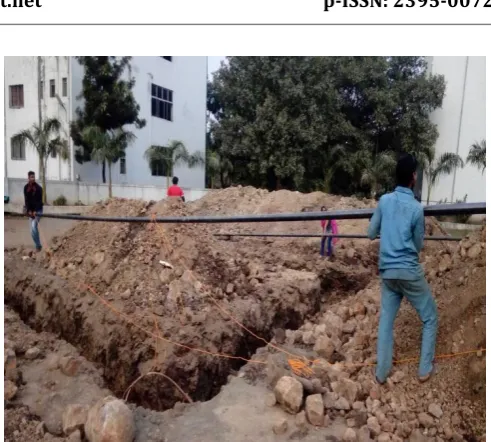
A 90° elbow at both the ends makes the inlet and outlet horizontal hence the entry of rain water in the system is prevented. Inlet is connected to the delivery end of blower and outlet end of ETHE pipe is kept open to the room. (Below figure shows the pipes installed).
Fig 1.2: Experimental Setup
[image:2.595.72.252.224.335.2]The outside air at ambient temperature is supplied in the system using a centrifugal blower. The air velocity is so adjusted to get optimum decrease in temperature (in this case 6 m/s). The air is then passed through the ETHE pipes. This air gets in contact with the MS pipe buried underground at a depth of 3 m where air rejects its heat to the pipe. The heat accepted by the pipe is then further rejected to the soil by conduction as soil is in direct contact with the pipe. In this case, heat transfer by convection is dominating over heat transfer by conduction. Air is the working fluid for the entire system. By rejecting heat to MS pipe, air temperature reduces and it becomes cooler. This cooled air arrives at outlet end of pipe from where it is supplied to the space which is to be air conditioned.
Fig 1.3: ETHE Piping
2. Mathematical Model
Flow rate of air at outlet of blower (Q)
Q = A × v
[image:2.595.311.561.496.664.2]© 2017, IRJET | Impact Factor value: 5.181 | ISO 9001:2008 Certified Journal | Page 5647 pv=
Friction losses per meter length (pf)
pf = 0.00268 ×
Elbow losses
Elbow losses = 0.25 × pv
Total pressure losses
pt = Total pf + Total elbow losses
Static pressure at blower outlet (ps)
ps = Total pressure losses – velocity pressure
ps = 4.6993 × bar
Q = 53.205 CFM
COP
Coefficient of performance is one of the measures of heat exchangers efficiency.
COP =
Qout = × Cp × (Ti – To)
Qout= Rate at which heat is exchanged between hot air and
cooler soil (W)
= Mass flow rate of air (Kg/s)
Cp = Specific heat of air (J/Kg °C)
Ti = Temperature of the air entering the pipe (°C)
To = Temperature of air at outlet (°C)
Win = Rate of energy input into the heat exchanger i.e. energy
consumed by blower.
Power consumed by the air blower
Ein =
2.1 Results and Discussions
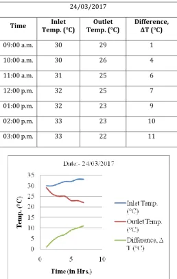
[image:3.595.304.563.126.534.2]The experimental investigation and the calculations were discussed in this chapter. Now the present chapter deals with interpretation of the obtained results. The aim of this project was to reduce the air temperature for the purpose of air conditioning of space. The maximum temperature difference obtained during the test conducted was 15 °C and the minimum temperature difference obtained was 8 °C.
Table 2.1:- Observations for temperature difference on 24/03/2017
Chart -1 : Graph of temperature Vs. time
Graph of Time vs. temperature is plotted. It can be seen that the temperature difference increases up to the peak day temperature is reached and then decreases gradually. The maximum temperature difference obtained for this day was 11 °C. The outlet temperature decreases up to the peak day temperature is reached and at a certain point inlet and outlet temperatures become equal and again outlet temperature increases gradually.
As explained in procedure, performance parameters of the system are observed. Observation is based on the obtained temperature difference between inlet and outlet air. COP of system is monitored on hourly basis.
24/03/2017
Time Temp. (°C) Inlet Temp. (°C) Outlet Difference, ΔT (°C)
09:00 a.m. 30 29 1
10:00 a.m. 30 26 4
11:00 a.m. 31 25 6
12:00 p.m. 32 25 7
01:00 p.m. 32 23 9
02:00 p.m. 33 23 10
© 2017, IRJET | Impact Factor value: 5.181 | ISO 9001:2008 Certified Journal | Page 5648
Table 2.2: Result Table for COP and heat energy extraction on 30/03/2017
Sr.
No (Hrs.) Time Diff. (° C) Temp. COP
Heat energy Extracted from
ground (kWh)
1. 09:00 a.m. 0 0 0
2. 10:00 a.m. 3 0.5 0.0927
3. 11:00 a.m. 6 1 0.3709
4. 12:00 p.m. 8 1.33 0.7419
5. 01:00 p.m. 10 1.66 1.2365
6. 02:00 p.m. 11 1.82 1.7003
7. 03:00 p.m. 15 2.5 2.7822
Chart -2 : Result for COP
Above graph shows that the COP of the system increases up to the point of peak day temperature is reached and then decreases gradually with decrease in day temperature.. COP is dependent on temperature difference obtained. After a peak temperature point is reached COP decreases with decrease in temperature difference and after certain point it becomes zero. Maximum COP is obtained at peak day temperature.
3. CONCLUSIONS
Observations taken shows that during cooling mode ETHE system can provide the maximum temperature difference of about 15 °C. The temperature difference can be further increased by reducing velocity of air passed through the pipe
so as to ensure contact between air and pipe for a longer period providing more time for heat transfer.
Graph shows that the COP of system increases gradually with time up to a peak day temperature is reached. The maximum value of COP obtained is 2.5.
Electrical energy calculations for blower showed that only 1.118 units of electrical energy are required to run the setup for 6 hours. In general, 5 star rated split A.C. having 1.5 TR capacity consumes 1.205 units per hour (considering compressor will run 80% of time). This shows that the cost of running the setup is very less compared to the AC. Thus we can conclude that the ETHE system can be substituted in the place of split ACs.
ETHE can be used as a supportive system for the conventional air conditioning systems.
[image:4.595.320.545.289.698.2]© 2017, IRJET | Impact Factor value: 5.181 | ISO 9001:2008 Certified Journal | Page 5649
REFERENCES
[1] Girja Sharan and Ratan Jadhav, Performance of Single Pass earth-Tube Heat Exchanger: An Experimental Study (2003)
[2] Vikas Bansal, Rohit Misra, Ghanshyam Das Agrawal and Jyotirmay Mathur, Performance analysis of earth–pipe–air heat exchanger for summer cooling, Energy and Buildings 42 (2010) 645–648
[3] Djamel Belatrache, Saïd Bentouba and Mahmoud Bourouis, Numerical analysis of earth air heat exchangers at operating conditions in arid climates, international journal of hydrogen energy (2016)
[4] L. Ramírez-Dávila, J. Xamán, J. Arce, G. Álvarez and I. Hernández-Pérez, Numerical study of earth-to-air heat exchanger for three different climates, Energy and Buildings 76 (2014) 238–248
[5] Ahmed A. Serageldin, Ali K. Abdelrahman and Shinichi Ookawara, Earth-Air Heat Exchanger thermal performance in Egyptian conditions: Experimental results, mathematical model, and Computational Fluid Dynamics simulation, Energy Conversion and Management 122 (2016) 25-38
[6] Saifullah Zaphar, Experimental Performance Analysis of Earth-Air Heat Exchanger for Energy Efficient and Eco-Friendly HVAC Systems, International Journal of Computer & Mathematical Sciences IJCMS ISSN 2347 – 8527 Volume 4, Special Issue February 2015
[7] F. Al-Ajmi, D.L. Loveday, V.I. Hanby, The cooling potential of earth–air heat exchangers for domestic buildingsin a desert climate, Building and Environment 41 (2006) 235– 244