© 2018, IRJET | Impact Factor value: 6.171 | ISO 9001:2008 Certified Journal | Page 917
‘
COMPARATIVE SEISMIC EVALUATION OF RESPONSE OF RC BUILDING
WITH SHEAR WALL FRAME AND DIFFERENT BRACING SYSTEMS
’
Amru shamil
1, Prof. D.J. Dhyani
21PG student, Department of civil Engineering, Sardar Vallabhbhal Patel of technology (SVIT), Vasad, Gujarat, India 2professor, Department of civil Engineering, Sardar Vallabhbhal Patel of technology(SVIT), Vasad, Gujarat, India
---***---Abstract -
In the presents study the seismic evaluation ofG+14 storey RC building using shear-wall and different kinds of bracing systems are carried out. The proposed model buildings are square shaped buildings. All structural members are designed in accordance with EURO CODE 8. The frame type of proposed model building used is the special RC moment resisting frame. In this study, response spectrum analysis technique is used for dynamic analysis. The analysis and design of the structure are carried out through the use of ETABS v 2015 software program. In this study shear-wall and different bracing systems are used to understand seismic response of the proposed buildings. The storey drifts, base shear, and maximum storey displacement results are compared.
Key Words: Response spectrum, base shear, Seismic, Story displacement and Story drift.
1. INTRODUCTION
The demands of high-rise buildings are increasing from time to time in metro cities due to the rapid growth of populations, cost of land, and limitation of spaces. As the height of the building increases, horizontal loads because of earthquake and wind loads becomes the governing loads. To withstand the lateral loads due to seismic loads and wind load to raises the stiffness’s of the structure or to increase the capacity of the building to resist the lateral load. The characteristics of the building at the time of earthquake shake mostly based on the stiffness, strength, and distribution of weight in both directions of the building. To decrease the impact of seismic loads shear-walls and steel braces are utilized as a part of the building. These can be utilized for enhancing the seismic response of the structure. The primary concern of structural design is the safety of the structure during a major earthquake, it is essential to guarantee adequate lateral stiffness to resist the seismic load. The introduction of different steel braces and shear wall on to reinforced concrete buildings to improve rigidity have been discovered effective and efficient [1]. Most commonly reinforced concrete shear walls are utilized in RC buildings due to good performance to resist earthquake loads, whereas different steel braces are frequently utilized in steel buildings due to the fact that steel braces are very effective and efficient techniques to withstand horizontal loads in a frame building [6]. In the past two decade bracing systems are utilized as retrofitting measures for tall buildings, however, recently many researchers have investigated that steel bracings are a viable alternative for RC shear wall in new buildings with the proper connections.
Patil, desai and khurd (2016) carried out “comparative analysis and design of 15 story RC building with shear wall and different types of bracing”. The modeling and analysis of the structure was done in ETABs software. Shear wall and different steel bracing systems are good in reduction of roof displacement and maximum story drift [2].
S.R. Thorat and P.J. Salunke (2014) discussed about “seismic response of braced concrete frames compared with that of shear frames”. They also studied the location of shear wall and brace elements. The location of shear wall and braced frame has important role on seismic response of the building [3].
Viswanth, Prakash and Desai (2010) “investigated the effect of the distribution of steel bracing along the height of RC frame on seismic performance of rehabilitated building in 4, 8, 12 and 16 storied building with various types of steel bracing”. They recommended to using X-type steel bracing system in order to increasing the stiffness of the structure and decreasing the maximum story drift of the structures [4].
Karthik reddy and kala kondepudi (2015) investigated “comparative study on behavior of multi-storeyed building with different types and arrangements of bracing systems”. Four different kinds of bracing systems have been examined for the utilization in tall building to give lateral stiffness [5].
2. METHODOLOGY
To determine the seismic parameters of G+14 storey RC buildings like maximum story displacement, story drift and base shear. “Equivalent static and Response spectrum method of analysis were carried out using ETABs 2015”.
3. MODELING
In the present paperwork, G+14 story Reinforced concrete building with shear wall and different types of bracing systems are considered.
Three types of models are considered for the analysis as given below:
Model 1: bare frame model (unbraced frame model)
Model 2: model frame building with shear wall and different bracing systems at corner of the model buildings
© 2018, IRJET | Impact Factor value: 6.171 | ISO 9001:2008 Certified Journal | Page 918 Table 1: Description of Members used
Number of stories 15
Storey height 3.5 m
Plan dimension 42 m*42 m
Number of bays in x and y
direction 7
Width of bays in x and y
direction 6 m
Slab thickness 0.15 m
Size of beam 400 mm*600 mm.
Size of bracing section 600 mm* 300 mm * 15mm Thickness of shear wall 0.3 m
Size of column 1-10 storey
11-15 storey
600 mm* 600 mm
[image:2.595.284.558.82.269.2]400 mm* 400 mm
Table 2: Material properties used for analysis
Material properties
Grade of concrete C-40
Grade of steel(rebar) S-500 Density of reinforced concrete 25 kN/m2 Modulus of elasticity of
concrete 35GPa for C-40
Modulus of elasticity of steel 200GPa Density of reinforcing steel 7850 kg/m Coefficient of thermal
expansion 10*10-6 per
o C
Poisons ratio of concrete 0.2 Poisons ratio of steel 0.3
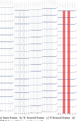
[image:2.595.29.313.99.326.2]Figure 1: plane view of 15 storey model building
Figure 2: 3-D view of bare frame model buildings
a/ bare frame b/ X- braced frame c/ V-braced frame d/ INT V-braced fame e/ shear wall
[image:2.595.310.565.313.713.2] [image:2.595.39.285.355.544.2]© 2018, IRJET | Impact Factor value: 6.171 | ISO 9001:2008 Certified Journal | Page 919 Loads: - The loads considered in this structural analysis are
dead loads, live loads and seismic loads.
Wall load- 7.2 kN/m (Assumed).
Live load and Floor load- 4 kN/m2 & 1.5 KN/m2
[image:3.595.304.567.80.412.2]Earthquake load: - The Seismic loads EQx and EQy are given in Load patterns directly using Code EN 1998-1: 2004. Seismic load used in the analysis is given in table below.
Table 3: seismic load used in the analysis
4. RESULT AND DISCUSSION
The linear static analysis and response spectrum analysis are carried out using analysis software ETABS2015. The response of bare frame, shear wall and different bracing systems results are obtained and results are compared. The response parameter considered in this study is Maximum roof displacement, Maximum story drift, base shear and time period. The reduction in every one of these responses at each story level is found out and reduction rate in percentage (%) is calculated.
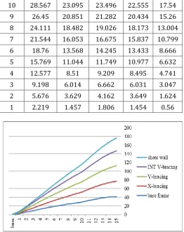
4.1 Maximum story displacement
[image:3.595.31.287.233.381.2]The maximum story displacements of 15 story bare fame model building, with shear wall and different types of bracing systems analysis results are given below in the table and graph respectively.
Table 4: maximum story displacement (mm) of model2 buildings
story bare
frame bracing X- V-bracing bracing INT V- shear wall
15 41.568 35.589 35.503 34.398 29.444 14 40.405 33.487 33.547 32.509 27.124 13 38.411 31.129 31.303 30.317 24.757 12 35.701 28.578 28.846 27.891 22.356 11 32.383 25.893 26.226 25.297 19.942
10 28.567 23.095 23.496 22.555 17.54
9 26.45 20.851 21.282 20.434 15.26
8 24.111 18.482 19.026 18.173 13.004 7 21.544 16.053 16.675 15.837 10.799
6 18.76 13.568 14.245 13.433 8.666
5 15.769 11.044 11.749 10.977 6.632
4 12.577 8.51 9.209 8.495 4.741
3 9.198 6.014 6.662 6.031 3.047
2 5.676 3.629 4.162 3.649 1.624
1 2.219 1.457 1.806 1.454 0.56
Figure 4: maximum stor displacements of model2 buildings
Table 5: maximum story displacements (mm) of model 3buildings
sto
ry frame bare bracing X- bracing V- bracing INT V- shear wall 15 41.568 33.301 34.215 33.793 30.041 14 40.405 31.599 32.545 32.176 27.98
13 38.411 29.609 30.567 30.21 25.841
12 35.701 27.383 28.336 27.957 23.621 11 32.383 24.972 25.898 25.482 21.33 10 28.567 22.388 23.263 22.799 18.99
9 26.45 20.315 21.182 20.722 16.714
8 24.111 18.091 18.977 18.48 14.411
7 21.544 15.782 16.664 16.142 12.103
6 18.76 13.394 14.254 13.718 9.811
5 15.769 10.945 11.762 11.225 7.572
4 12.577 8.466 9.212 8.694 5.442
3 9.198 6.007 6.644 6.175 3.498
2 5.676 3.64 4.116 3.738 1.846
1 2.219 1.466 1.726 1.493 0.616
Subsoil class B
Behavior factor, q Depends on the types of the structural systems
Seismic zone V
Bedrock acceleration ratio (α0 = a0 /g) (ratio of design
bedrock acceleration to acceleration of gravity)
0.2g
Importance factor, I 1
[image:3.595.64.560.490.787.2]© 2018, IRJET | Impact Factor value: 6.171 | ISO 9001:2008 Certified Journal | Page 920
Figure 5: maximum storey displacements of model 3buildings
4.2 STOREY DRIFT
[image:4.595.36.287.67.237.2]Story drift of 15 storey RC frame building with shear wall and different bracing types are given in graph as follow
Figure 6: average maximum storey drift of model 2 Buildings
Figure 7: average maximum storey drift of model 3
[image:4.595.308.560.153.429.2]buildings
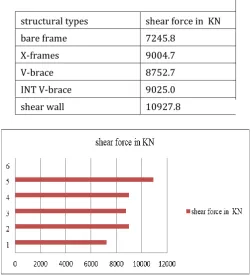
Table 6: base shear force for model2 buildings
structural types shear force in KN
bare frame 7245.8
X-frames 9004.7
V-brace 8752.7
INT V-brace 9025.0
[image:4.595.40.290.344.502.2]shear wall 10927.8
Figure 8: base shear for model 2 buildings
Table 7: base shear for model 3 buildings
structural types shear force KN
bare frame 7245.8
X-frames 8755.9
V-brace 8463.2
INT V-brace 8729.3
shear wall 11338.5
Figure 9: base shear force for model 3 buildings 4.3 BASE SHEAR
[image:4.595.38.564.424.739.2] [image:4.595.244.546.471.747.2]© 2018, IRJET | Impact Factor value: 6.171 | ISO 9001:2008 Certified Journal | Page 921 4.4 TIME PERIODE
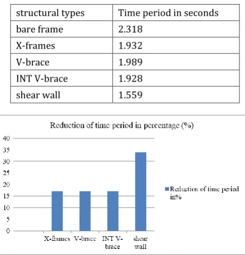
[image:5.595.38.280.157.409.2]The fundamental time period of 15 story model buildings are given in the table and figure below.
Table 8: time period for model 2 buildings
structural types Time period in seconds
bare frame 2.318
X-frames 1.932
V-brace 1.989
INT V-brace 1.928
shear wall 1.559
Figure 10: reduction of time period in percentage for model 2 buildings
Table 9: time period for model 3buildings
structural types Time period in seconds
bare frame 2.318
X-frames 1.875
V-brace 1.925
INT V-brace 1.867
shear wall 1.617
Figure 11: Reduction of time period in percentage for model 3buildings.
5. CONCLUSIONS
Based on the analysis results and discussion the following conclusions are drawn
Providing shear wall and different bracing systems at different location can affect the lateral stiffness and strength of reinforced concrete frame buildings.
Providing shear wall and different bracing system in proper location severely reduces the maximum storey displacement and storey drift.
Steel bracing system can be utilized as an alternative to replace shear wall on new buildings be side using it as retrofitting.
Generally when steel bracing is introduced to the building the lateral stiffness and strength of the building increases
REFERENCES
[1] Chandurkar.et.al. “seismic analysis of RCC building with
and without shear wall” international journal of modern engineering research. Volume 3,pp-1805-1810,2013.
[2] Patil S.p, Desai R.M, Khurd V.G “comparison of shear wall
and bracing in RCC framed structures” international journal for research in applied science and engineering technology .vol 4 pp. 2321-9653. 2016.
[3] S.R. Thorat and P.J. Salunke “Seismic Behavior of
Multistory Shear Wall Frame Versus Braced Concrete Frames “ International Journal of Advanced Mechanical Engineering Volume 4,pp. 323-330, 2014.
[4] K.G Viswanath, K.B Prakash, D.Anant (2010) ‘Seismic
analysis of steel braced Reinforced concrete frame’ international journal of civil and structural engineering”. 114-122.
[5] Karthik reddy and kala kondepudi.”a comparative study
on behavior of multistoried building with different types and arrangement of bracing systems”. International journal of science and technology and engineering, Volume 2, pp. 2349-784X, 2015.
[6] M.R Maheri and A.Sahebi. ”Use of steel bracing in
reinforced concrete frames "engineering structure vol.19 no.12 oct 1996.
[7] EN. Draft n. 6 of Euro Code 8: Design Provisions for
Earthquake Resistance—Part 1: General Rules, Seismic Actions and Rules for Buildings. European Committee for Standardization: Bruxelles, 2003.
[8] CEN. Euro Code 3: Design of Steel Structures—Part 1-1: