© 2017, IRJET | Impact Factor value: 5.181 | ISO 9001:2008 Certified Journal | Page 33
Military Spying & Bomb Diffusing Robot with Night vision
Richa Parmar
1, Akash Malik
2, Attarwala Shahnawaz
3, Barot Parth
4 1Richa Parmar, Student, Dept. of EC, Govt. Eng. College, Bharuch, Gujarat, India
2Akash Malik, Student, Dept. of EC, Govt. Eng. College, Bharuch, Gujarat, India
3Attarwala Shahnawaz, Student, Dept. of EC, Govt. Eng. College, Bharuch, Gujarat, India
4
Barot Parth, Student, Dept. of EC, Govt. Eng. College, Bharuch, Gujarat, India
---***---Abstract - In certain applications, many times it is not desirable for a human to go to a certain place physically. Applications like detecting and diffusing a bomb, spying a place or detecting a land mine are examples of such situations. Our advance military robot will be very helpful in such situations with the help of a night vision camera, and two robotic arms which can grab objects and cut wires and hence it can be sent to such dangerous locations and can be accomplish the objectives.
Key Words: Bomb Diffusing, Spying, RF Communication, Metal Detection, Night Vision Camera, PIC controller.
1.
INTRODUCTION
Our project is designed keeping in mind, the view of the current civil wars, military instability and terrorist scenarios across the globe. Almost every day so many trained people gets either injured or loses their lives while dealing with or trying to defuse bombs. All this can be perceived by the countless number of news articles and documentaries that appears daily on news channels and print media around the world.
Though the idea of our project is original, some projects with similar objectives can also be found. Examples of the French Police have a bomb disposal robot, the Army of Israel possesses it and it is also in use by the bomb squads in a number of states of USA.
The main idea of the robot here is to serve the bomb disposal squad with proving safety and security from the dangers that they are facing in their daily lives. The bomb squads in India have metal detectors and may be some other equipment for detecting the bomb and disposing it, but still they have to keep their lives at risk by going near the bomb physically or the suspicious packets without any safety and precautions. Our robot will serve as an extra layer of protection to the bomb squad members by giving them the facility to simply check and analyse any suspicious packet and further if detected, the robot can be instructed to diffuse it too.
A mobile robot generally reduces or eliminates a bomb technician’s time on target. The robot also takes the danger out of potentially deadly scenarios and allows the bomb technician to focus on his work of what he needs to do to the explosive material rather than deviating on topics of the threat to life and his limbs. Now, even if in some cases the robot may not reach near the suspicious item for disruption, it can still be used to pass the information to help the technician and deciding what needs to be done. Apart from all this, the visuals recorded by the robot’s camera can provide evidences for further research and analysis.
1.1 Objective of the project:
The main goal of our project is to give safety to the bomb squad members and serving an extra line of defense while dealing with the bomb. The main objective will be accomplished only by completing several sub objectives. These sub objectives are as given below -
Serve as distant monitoring and controlling device to check any suspicious packet (or bomb).
To allow the user to manipulate the suspicious packet using the robotic arms.
To give visual display from the place of the packet.
To make the controlling of the robot such that it can be controlled very easily.
This uses project serves as a control application, at the user end to control the robot from some distance using wireless technology.
The bomb technician will also control the robot using a switch box. This input from the user will be transmitted serially by RF signals to the robot, where it will receive, identify and will further instruct the robotic module.
The input to this project will be from the user.
Here the inputs from switches will be first processed at the user side, serially transmitted over a Radio Link. This input is then received at the robot and will be processed again.
The output of the system is then processed into a signal that can instruct the appropriate module.
This module will be a motor of the wheels of the robot or the robotic arm.
© 2017, IRJET | Impact Factor value: 5.181 | ISO 9001:2008 Certified Journal | Page 34
1.2 Major Inputs and Outputs:
Input Signals from Switches
Video Feedback
Movement of Robotic Arm
Movement of Base
1.3 Conventional Wireless Robotics:
In conventional robotics, the controlling and operation of robots is usually done by using RF [Radio Frequency] circuits. These circuits are widely used for control and working applications and are also reliable over a small range. The RF circuits consist of transmitter and receiver which are independent of each other. All the control signals and commands are sent via wireless medium in between transmitter and receiver.
There are a number of advantages of RF circuits such as Low cost, Ease of Construction & design, easy decoding, less maintenance cost etc. Besides these advantages, there are still many serious drawbacks of using a RF circuit in circuit.
They are:
Limited Frequency Range:
The frequency range used for typical RF communication is near about 3 KHz -3GHz. The use of channel separator increases the reliability but decreases the actual usable working frequency range.
Limited Functions:
The limited number of channels causes less number of combinations and thus there are less numbers of available functions.
Limited Working Range:
The working range of RF circuits with transmitters and receiver is very small. It starts from a few meters to a few kilometers. The working varies from circuits to circuits, but mainly depends on the values of physical components used in the circuit. Mainly Wi-Fi and Wi-Max wireless services are used in RF transmitter and receiver circuits. The following table shows the actual working range of different wireless standards that can be used in wireless communication.
Reliability of Operation:
The RF circuits are very prone to errors due to external conditions such as EMI (Electro-Magnetic Interference), medium saturation, absorption due to repetitive reflections from surface. Hence the output recovered is not always what is expected. This might be a serious problem when working with scientific experimental components.
Security reasons:
This is the main disadvantage of using a RF circuit and the main reason why RF circuits are not preferred today. The RF
frequency band is available for almost all the users for data communication. So there might be a scenario where more than one user is trying to accommodate channel for its own communication. In such case the frequency band may get interference from another user. Or worst case would be, some user intentionally trying to jam our communication network. The RF jammer circuits are very easy to design; hence the question of security arises when RF circuit is used in the circuit. This security loop hole can be very dangerous when the robot is being used for very confidential purposes. In areas of military these security threats can produce disastrous outcomes.
2. PROJECT METHODOLOGY
2.1 Block Diagram:
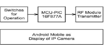
[image:2.595.307.522.332.426.2]2.1.1 Transmitter:
Fig. 1: Transmitter Block Diagram
In the transmitter section, we can observe that there are switches for controlling of robot which are on the remote control which is interfaced with PIC 16F877A controller. After receiving the signal from the switches, the micro controller will generate signals through USART pins for the RF module. Thus RF module will finally transmit the signal to the receiver part.
Also, we are using an android mobile for the display of the visual display of the camera at the robot. The video will be communicated by IP Web Camera application of Android OS.
[image:2.595.310.527.648.741.2]2.1.2 Receiver Block
© 2017, IRJET | Impact Factor value: 5.181 | ISO 9001:2008 Certified Journal | Page 35
In the receiver section, we can observe that there is a RFmodule receiver that will receive the transmitted signal from the RF module placed at the transmitter section. After receiving the single, it is sent to the PIC 16F877A microcontroller. The program stored in the microcontroller will direct the motor’s operation according to the positions of switches at the operator side.
The mobile placed on the robot will capture the visuals and will send it to the operator side by the IP Web Camera app.
3.
LITERATURE REVIEW
3.1 Hardware Description:
3.1.1 PIC 16F877A Microcontroller
The microcontroller IC of the PIC 16F877A is one of the most used microcontrollers of the era. This controller IC is very easy for use and programming the controller is also relatively easier when compared with other microcontrollers. One of the main advantages of this microcontroller is that it provides RAM memory which can be rewritten as many times as the user desires. PIC 16F877A is used in many PIC microcontroller projects. PIC 16F877A IC also have many applications in embedded electronic circuits.
It has a total number of 40 pins and there are 33 pins for input and output in which specifically there are 5 ports named as A , B , C , D and E.
[image:3.595.333.536.172.361.2] A port has 6 pins, B, C and D ports have 8 pins each. Port E has 3 pins. Function wise there are 8 analog pins, 2 UART pins, 2 PWM pins.
Fig. 3: PIC IC
Apart from all this, PIC controller comes with inbuilt ADC.
The IC works on 12 MHz of frequency that is supplied by crystal.
Fig. 4: Pin Configuration of PIC
3.1.2 RF Module
The main objective of the wireless device used in this project is to serve as a means for wireless communication between the user and the robot.
We will be using RF serial data link UART 2.4 GHz model number 1418 which will provide the data transmission serially at 9600 baud rate by the transmitter and receiver and the range will be around 50 meters.
[image:3.595.49.263.577.735.2] Here, signals from the user are processed by the PIC microcontroller and then is transmitted from Rx – Tx ports of the PIC, and is then received by the RF receiver module placed at the robot.
Fig. 5: RF Module
© 2017, IRJET | Impact Factor value: 5.181 | ISO 9001:2008 Certified Journal | Page 36
3.1.3 Metal Detector For detection of any metal we will fix a metal detector on the front side of our robot.
The metal detector can be used to detect slightly big metallic objects, it uses a sensing coil which will be kept near metallic object for detection.
The input of the circuit will be colpitt's RF range oscillator which will have a sensing coil as part of tuned oscillator.
When coil is brought near a metallic object, magnetic energy is observed and oscillator fails to work which leads final transistor to conduct and corresponding signal will be sent to the transmitter.
3.1.4 Camera
For video transmission we will use a pair of mobile phones one each at transmitter and receiver.
The mobile phone at receiver end will record video and sent it in real by an android application through internet to transmitter.
For night vision purpose we will use infrared LEDs. 3.1.5 LM 298 Motor driver IC
Fig 6: LM 298 IC
This is again a very popular and economically feasible motor driver IC known as L298.
It can control two motors at a time.
Currents up to 1.2 amps per motor can be handled by the IC, but to get the maximum current proper heat sinks are necessary.
The L298 has a large metallic heat sink with a hole in it, making it easy to attach a homebrew metal heat sink to it.
3.1.6 DC Motors
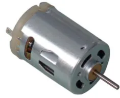
[image:4.595.328.446.185.281.2] A DC motor is a transducer that converts electrical power into mechanical power by the means of electromagnetic fields.
Fig. 7 DC motor
In this project, we are using two types of DC motors which have specifications of 60 rpm and 10 rpm.
The 60 rpm motor will be used for wheels of robot. More rpm is used here so as to increase the speed of robot.
And 10 rpm motor will be used for movement of arms. Here lesser rpm is used so as to make the arms more precise.
3.2 Software Description:
3.2.1 Proteus 8:
Proteus 8 is an application which provides various function such as laying PCB design, schematic capture, and programming can be loaded and virtual simulation can be done. The version of Proteus is better than the previous version as it provide better application and has common data base which provide the feature of accessing schematic capture and PCB layout in synchronized way.
3.2.2 Mikro C:
© 2017, IRJET | Impact Factor value: 5.181 | ISO 9001:2008 Certified Journal | Page 37
3. CONCLUSIONSAlthough we have completed the project with the aim of cost efficiency, in the future to make the product effective still lots of improvements that can be made on the current design and technology and lots of additional features can be added. Like Compact design, Quick movement, improved reliability, Night vision camera, Replacement transmitter with low power transmitter &receiver with highly sensitive to reduce the power consumption or Robotic arm can be attached.
REFERENCES
[1] G. Vashisht, Rahul D., “ Defense survillience robot based
on RF and DTMF technology”, in IJAREEIE.
[2] K. Borker, R. Gaikwad, A. Rajput, “ Wireless controlled
survillience robot”, in IJARCSMS.
BIOGRAPHIES
Richa Parmar is a final year student of Electronics and Communication at Government Engineering College, Bharuch. Her specialization lies in Automation.
Barot Parth is a final year student of Electronics and Communication at Government Engineering College, Bharuch. His specialization lies in hardware components.
Attarwala Shah Nawaz is a final year student of Electronics and Communication at Government Engineering College, Bharuch. His specialization lies in Embedded Systems.