© 2017, IRJET | Impact Factor value: 5.181 | ISO 9001:2008 Certified Journal | Page 1164
DESIGN AND IMPLEMENTATION OF AN EFFICIENT SOFT SWITCHING
INVERTER FED AC DRIVE
Mahesh Kumar K M
1, Dr. P S Puttaswamy
2,
1
Assistant Professor, Dept. Of E &E, PESCE, Mandya, India
2
Professor, Dept. Of E &E, PESCE, Mandya, India
---***---Abstract -
the purpose of this paper is to design and Implement the soft switching inverter for the ac motor drives. The soft switching topology is presented and principle of operation is described in details. Soft switching has the potential of reducing switch stresses and of lowering the switching losses as compared to hard switching. For this reason, several soft switching topologies have been presented in the literature.Key Words: soft switching, inverter, PWM, MOSFET, AC Motor
1.INTRODUCTION
In conventional dc-ac power conversion, the input toPWM inverters is a stiff dc voltage supply and the power switches operate in a switch mode. Therefore, the power devices are subjected to high switching Stresses and switching power losses that increase linearly with the switching frequency of pulse-width Modulation. High switching power losses not only restrict switching frequency, but also reduce the system efficiency and produce tremendous heat inside the inverter. This compels the industrial personnel to use larger heat sinks, which result in increased volume and weight of the system. In addition to these limitations, the system suffers from other shortcomings such as EMI and acoustic noise.The increased demand for high power density converters in aerospace, defense and telecommunications has prompted researchers to design converters capable of operating at a high switching frequency and without the adverse effects of PWM converters. These application areas also impose constraints upon the size, weight and volume of the converters to enable them to accommodate greater payloads. The benefits of high frequency converters have been recognized and their importance has significantly increased. Remarkable efforts have been made in the development of high-frequency voltage switching (ZVS) and zero-current switching (ZCS) dc-ac power converters, which can now realize power supplies that are highly dynamic, high performance with negligible noise. In these converters, the principle of resonance is used in order to implement the soft-switching techniques (ZVS/ZCS) for various devices in the resonant link and the inverter.
The driver based soft switch concept was originated from development of a base driver circuit for current driven bipolar junction transistor (BJT). A new insulated-gate-bipolar-transistor (IGBT) and power metal-oxide-semiconductor field-effect-transistor (MOSFET) gated transistor (IMGT) base drive structure was initially proposed for a high power SiCBJT. The proposed base drive method drives SiCBJTs in a way similar to a Darlington transistor. With some modification, a new base driver structure can adaptively achieve zero voltage turn-on for BJT at all load current range with one single gate. The proposed gate driver based soft switching method is verified by experimental test with both Si and SiCBJT. The idea is then broadened for “soft switch” implementation. The whole soft switched BJT (SSBJT) structure behaves like a voltage-driven soft switch. The new structure has potentially inherent soft transition property with reduced stress and switching loss. The work in this paper presents the concept of “soft switch”. The goal of “soft switch” is to develop a standard PWM switch cell with built-in adaptive soft switching capabilities. Just like a regular switch, only one PWM signal is needed to drive the soft switch under soft switching condition. The core technique in soft switch development is a built-in adaptive soft switching circuit with minimized circulation energy. The necessity of minimizing circulation energy is first analyzed. The design and implementation of a universal controller for implementation of variable timing control to minimize circulation energy is presented. To simplify the control, several methods to achieve soft switching with fixed timing control are proposed by analyzing a family of zero-voltage switching converters.
2. LITERATURE SURVEY
These resonant links are embedded in different locations of the inverters depending upon their configuration. The progress of soft switching techniques has passed through various stages during the last two decades.
© 2017, IRJET | Impact Factor value: 5.181 | ISO 9001:2008 Certified Journal | Page 1165 in the converter systems, characteristics of switch
waveforms (ZVS/ZCS), and types of resonance
A) Load Resonant DC-AC Converters: In load resonant dc-ac converters, an LC resonant tank is added to the load side in series, in parallel, or in a combination of series and parallel LC schemes. The resonant tank oscillates with a resonant frequency (fr) during the entire switching period (Ts = 1/fs, fs is converter frequency). As a result, the resonant tank produces the oscillating load voltage and current waveforms, which create ZVS and/or ZCS conditions for the switching devices
B) Resonant link inverters : In resonant link inverters, the resonant network is connected between the source and the inverter bridge. The resonance of this network is utilized to bring the link voltage or current periodically down to zero to create a soft-switching condition. Resonant link inverters are classified according to the type of resonance employed in the link. Primarily, they are known as resonant ac link (RACL) and resonant dc link (RDCL).
C) Resonant AC link Inverter: A resonant ac link using series resonance was reported by Klaassens .Sul and Lipo reported a resonant ac link based on parallel resonance suitable for an induction motor drive. The main shortcomings of the resonant ac link inverter are that it requires a large number of devices and the control circuit becomes quite complex.
D) Resonant DC link Inverter Resonant networks are placed between the source and the inverter. They are classified as (a) series resonant dc link (SRDCL) and (b) Parallel resonant dc link (PRDCL).
Murai and Lipo proposed the concept of SRDCL in 1988. In this scheme, the resonant components Lr and Cr constitute a series resonant link and the inductor Ld is used for biasing
purpose. By establishing an appropriate biasing current in Ld, the link current is made unidirectional. the bulky biasing inductor makes this topology not very attractive.
The concept of PRDCL was put forth by Divan. In this scheme, a dc bias voltage is provided to the dc link so that the link voltage becomes unidirectional. As a result, the number of unidirectional devices used is reduced as compared to the SRDCL and the cost and complexity of the power modulator is also further reduced
Resonant Transition DC-AC INVERTER: The problems of reduced voltage PRDCL inverters can be overcome by using the principle of resonant transition. In a resonant transition inverter, the soft-switching condition is implemented by resonating the voltage and/or the current across inverter switches. The inverters based on the principle of resonant transition technique may be classified into following three categories.
(a) Soft-transition PWM inverter (b) Resonant snubber inverter (c) Quasi-Resonant inverter
Soft switching for the power devices can be achieved by either zero-voltage switching (ZVS) or zero-current switching (ZCS).ZVS consists of turning on the switches while the voltage across them is zero. ZCS consists of turning off the switches when the current through them is zero. Common to all approaches of soft switching is the use of reactive elements to shape the current and voltage waveforms to achieve the necessary conditions for ZVS or ZCS. Soft switching has been proven to be an effective means of reducing switching losses and for attaining higher overall efficiencies. Various soft-switching techniques have been developed in the recent years.
Advantages of soft switching are as follows:
Lower switching losses due to smaller overlap of switch voltage and current
Lower dv/dt and di/dt and thus lower voltage spike and EMI emissions
Higher reliability due to reduced stresses on the switching components
© 2017, IRJET | Impact Factor value: 5.181 | ISO 9001:2008 Certified Journal | Page 1166
3.
PROPOSED WORK
3
.1
Block Diagram
input dc
MOSFET drive
Rectifier Sensing circuit
AC motor
PWM Generator
IC 3843
H-bridge IGBT(120D)
drive
High frequency transformer
The main object of our project is to design a soft switching inverter for the ac drives. 12volt with current rating of 1amps is fetched from battery source and given to the PWM generator in order to generate the PWM signals. These signal is given to the MOSFET drive the AC output from the MOSFET drive is given to the high frequency ferret core transformer which step-up the 12volt AC to 300volt AC with same frequency. This output voltage is given to the rectifier in order to convert the AC to DC which is required for the IGBT drive. The output from the rectifier is having a high frequency of 12.5khz.in order to convert these high frequency to standard frequency of 50hz and also to convert DC to AC h-bridge IGBT drive is mainly act as a soft switching inverter. The final output will be pure sin wave which is given to the AC motor.
Addition to this a sensing circuit is also used to sense the high current and low voltage. Whenever the voltage is very low it gives an indication and when the current is very high in the circuit the tripping action will take place and it protects the device.
AC MOTOR
AC motors are used worldwide in many residential, commercial, industrial, and utility applications. Motors transform electrical energy into mechanical energy. An AC motor may be part of a pump or fan, or connected to some other form of mechanical equipment such as a winder, conveyor, or mixer. AC motors are found on a variety of applications from those that require a single motor to applications requiring several motors.
An asynchronous motor (by induction) works as follows: The coils placed at the stator are connected to an alternate current and the work as inductor. The changing magnetic
field induces a current in the rotor and a force is exerted on it. As a consequence the rotor rotates
Here the motor used is single phase un synchronized ac motor of rating 0.25hp with a voltage of 230 volts and current rating of 1 amps.
3.2 Circuit Diagram
A 12 volt 7 AH and 12.5khz dc supply is given to the PWM generator IC UC3843.The function of this IC is to generate PWM signal with a high frequency. The frequency is controlled by a feedback resistor of 220kohm. The output from the PWM generator is given to the MOSFET in order to increase the range of signal. In the gate of MOSFET the signal is alternatively get switched on and switched off, there it will convert DC to AC.
The output voltage from the MOSFET fed drive inverter is low and this output is step-up to a voltage level of 300volt-325volts by using a ferret core transformer. The main function of this transformer is to operate at high frequency, because the inverter output frequency is very high which will affect the core of other transformers like iron core. Iron core will only operate in lower frequencies. The output of the transformer is again rectified in order to get the standard frequency which is required for the real time application.
© 2017, IRJET | Impact Factor value: 5.181 | ISO 9001:2008 Certified Journal | Page 1167 freewheeling diode to suppress the high voltage surges in the
inductor.
In this cycle T4 and T5 will start to conduct .The gate pulse required for the triggering of the IGBT is given by the IC IR2153.the output from the H-bridge is SINUSOIDAL WAVE with standard frequency 50hz given to drive the AC motor
3.3
CURRENT SENSING CIRCUIT:
.
The current sense input is configured as shown in
Figure. Current-to-voltage conversion is done
externally with ground-referenced resistor Rs. Under
normal operation the peak voltage across Rs is
controlled by the E/A according to the following
relation:
where VC = control voltage= E/A output voltage.Rs can
be connected to the power circuit directly or through a
current transformer, as Figure illustrates.
While a direct connection is simpler, a transformer can
reduce power dissipation in Rs, reduce errors caused
by the base current, and provide level shifting to
eliminate the restraint of ground-referenced sensing.
3.4
The oscillator is programmed as shown in Figure.
Timing capacitor CT is charged from VREF (5V)
through the timing resistor RT, and discharged by an
internal current source. The first step in selecting the
oscillator components is to determine the required
circuit dead time. Next, the appropriate RT value is
interpolated using the parameters for CT and oscillator
frequency.
3.5
SHUTDOWN TECHNIQUES
:
Shutdown can be
accomplished by two methods; either raise pin 3 above
1 V or pull pin 1 below a voltage two diode drops above
ground. Either method causes the output of the PWM
comparator to be high (refer to block diagram). The
PWM latch is reset dominant so that the output will
remain low until the next clock cycle after the
shutdown condition at pin 1 and/or 3 is removed.
4.
RESULTS AND DISCUSSIONS
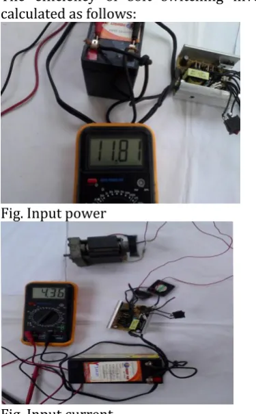
4.1 Soft switching inverter efficiency:
[image:4.595.42.285.216.340.2]The efficiency of soft switching inverter can be
calculated as follows:
[image:4.595.308.496.395.698.2]Fig. Input power
Fig. Input current
Input current of 4.36amp
Input voltage of 11.81v.
© 2017, IRJET | Impact Factor value: 5.181 | ISO 9001:2008 Certified Journal | Page 1168
Output voltage=199.8v
Output
power=V*I*cosᵩ
=199.8*0.42*0.6=50.34Watts
Efficiency η=output/input =97.78%
4.2 Heat sink Temperature of hard-switching and
soft-switching
The heat sink temperature of the hard-switched converter
is too high that it is very difficult to further push the out
power to anything beyond 2kW. The soft switched
converter however, can easily run at 2.8kW with only
little temperature rises on a small heat sink. The loss in
the magnetic cores is not counted in the temperature rise
since the core is not mounted on the heat sink.
CONCLUSIONS
The paper proposed and implemented a novel soft switching inverter topology for a AC motor. The scarcity of research in the field of soft switching was identified. A novel
soft-switching topology was presented Various components of this inverter were designed. The hardware implementation of all the relevant subsystems was presented. To verify the functionality of the inverter, it was used to run a AC Motor. All the relevant waveforms were captured and the efficiency of the inverter was calculated
The following observations were made:
A near zero voltage turn-on was achieved for the main switches.
Turn-off losses were reduced by using the
snubber capacitor.
Freewheeling diodes turned off under zero
current condition and this greatly reduced the reverse recovery problem of the diodes. Due to all the above effects, the switching losses
are considerably reduced.
Soft switching results in considerably less noise than in the hard switching case
An improvement in efficiency of the inverter was observed in the soft switching case. Hence, the proposed topology has been successfully implemented and its effectiveness has been verified.
REFERENCES
[1] soft-switching dc-ac converters:-a brief literature review,b. Panda et. al. / International Journal of Engineering Science and Technology Vol. 2(12), 2010, 7004-7020
[2]A Literature Review on Soft Switching DC-AC Converters, Swathy Soman, Chithra R International Journal of Engineering Research & Technology
[3]A novel soft-switched PWM inverter for AC motor drives, Shaotang Chen, T.A. Lipo, IEEE Transactions on Power Electronics
[4] A Novel Matlab/ Simulink Model Of A Softswitching Converter For Brushless Dc Motor Drives, Souvik Ganguli, International Journal of Advanced Engineering Technology
[5] T. Kenjo and S. Nagamori, Three phase induction Motors, Clarendon Press, Oxford,U.K., 1985.