LANa/yzer
:><'
I-LAN
"Excellence in Local Network Technology"RELEASE NOTES LANalyzer EX 5000E Ethernet Network Analyzer
2180 Fortune Drive San Jose, CA 95131
(408) 434-2300 TELEX 176610
February 10, 1986
The LANalyzer EX 5000E Ethernet Network Analyzer software, along with the EXOS 225 Ethernet Network Analyzer board, are designed for use on an IBM PC XT, IBM PC AT, or compatible system.
You should read these release notes as well as the manual before installing and using the EXOS 225 board and the EX 5000E software. Refer to the LANalyzer EX 5000E Ethernet Network Analyzer User Manual for complete information on installing and using the LANalyzer software and hardware. If you should have any questions, comments, or suggestions, please contact
Product Engineering Excelan, Inc. 2180 Fortune Drive San Jose, CA 95131 (408) 434-2285
COMPONENTS
contains one EXOS 225 board, the LANalyzer User Manual, one transceiver, and transceiver cable. Chapter 2 of the manual describes the procedures for installing the LANalyzer hardware and software.
As shipped, the EXOS 225 board is compatible with Ethernet Version 1.0, Ethernet Version 2.0, and IEEE 802.3 transceivers.
The EXOS 225 board has been tested in the following systems:
• IBM PC XT
• IBM PC AT
• AT&T 6300
• COMPAQ PORTABLE 286
• COMPAQ PLUS
• COMPAQ DESKPRO 286
• Wyse PC
• Sperry PC
When configured in PC-compatibility mode, the bus speed supported by the EXOS 225 board is 4.77 MHz. When configured in AT-compatibility mode, the bus speed supported by the EXOS 225 board is 6 MHz.
REMINDER
Your feedback on this software is appreciated. An overall evaluation form, as well as a software problem report form, are included at the end of these release notes. Please complete them and return them to Excelan.
LANALYZER EX 5000E FILES
The EXOS·· 8051 software is distributed on two floppy disks. The contents of the hardware diagnostics and installation diskette are as follows:
File
BINS.BAT CURFIX.EXE D225.EXE INSTALL.EXE INSTALL.INF OB.BAT PC225.EXE RUNDIAG
Contents/Purpose
Installation batch file Diagnostics. file EXOS 225 diagnostics Install program
Control file for INSTALL program Diagnostics control file
File BINS.BAT CMON.TPO COLLlSIO.TPO DATHD.TPO DEFAUL T.TST DIN.EXE FILL.TPO HOSTNAME.TPO HOSTS.TST INSTALL.EXE INSTALL.INF IPATM.TPO IPTM.TPO LANZ.EXE LANZDRIV.EXE LANZLOAD.EXE LANZRUN.BAT LOADNET. TST LYNX.TST MON.TPO MONITOR.B6 PAT.TPO PKT.TPO PKTDAT.TPO PKTSUM.TPO SEARCH.TPO STATION.TPO STATUS.TPO STNHDR.TPO SUMHD.TPO TEST.TPO TIME.TPO Contents/Purpose
Installation batch file
Object file for LANalyzer screens Object file for LANalyzer screens Object file for LANalyzer screens DEFAULT sample test
DIN command
Object file for LANalyzer screens Object file for LANalyzer screens HOSTS sample test
Installation command
Control file for INSTALL program Object file for LANalyzer screens Object file for LANalyzer screens LANalyzer invocation command
Commands for loading the LANalyzer driver Command for loading the EXOS 225 board code
Batch file for loading the LANalyzer driver and EXOS 225 board code
LOADNET sample test Base-level LANalyzer test Object file for LANalyzer screens EXOS 225 board code
software distribution. This program displays trace files in TCP/IP format. It can also be used to print the contents of LANalyzer trace files. DIN is described in detail later in these release notes.
KNOWN BUGS AND PROBLEMS WITH THE LANAL YZER EX 5000E
The following list enumerates the known bugs and problems in this release of the LANalyzer EX 5000E. Please inform Excelan if you find any additional problems.
• In the Collect Additional Packets field on the Edit Test screen, if you enter a value greater than 64K, the value used is the entered value mod 64K.
• An error . message that either the trace file or the statistics file is full most likely means that the hard disk is full.
• If during installation you encounter the following error messages, you should ignore them:
- Null pointer assignment
- Bad command file name
- File not found
• You should not overwrite the supplied sample tests (DEFAULT, HOSTS, and LOADNET). These tests are located in the directory \XLN\LANZ.
Command
Purpose: Displays LANalyzer trace file in Internet format.
Format: DIN [-b n] [-d] filename
Remarks: Specify the parameters:
Description:
[-b n] to curtail the amount of packet data displayed to a maximum of n bytes.
[-d] to enable debugging statements.
DIN interprets a LANalyzer trace file according to the Internet protocol standards. It recognizes Ethernet, IP, ICMP, and TCP protocol header formats. For each protocol layer, DIN prints a line or lines listing the protocol name and the header information. When DIN reaches a protocol layer it . does not understand, it prints the remainder of the packet in hexadecimal! ASCII memory dump format.
For all packets, DIN displays the Ethernet header and LANalyzer trace information as in this example:
ether: IP 08-00-14-30-02-26 - 08-00-02-00-18-3 t
82 913.931 14.645
since the previous packet was received.
A DIN command in the following format can be used to prepare the contents of a LANalyzer trace file to be printed:
DIN [options] filename > newfile
The file new file can be printed with the appropriate command.
IP Packets
For all IP packets, DIN prints a line as in this example:
ip: TCP alaska - idaho
The protocol type and Internet addresses are shown in symbolic format, if known. DIN looks up the name corresponding to an Internet. address in the HOSTS file. If the HOSTS file does not contain a corresponding name, then DIN prints the Internet address as two hexadecimal numbers separated by a period. The first number is the network number; the second number is the remainder of the address.
DIN scrutinizes each IP packet for inconsistencies and unexpected values." For' each anomaly, it prints one of the following error messages:
ip: BAD LENGTH: IHL=%d, TL=%d, PKT=%d The IP header length, IP packet length, and/or Ethernet packet length are inconsistent.
The IP protocol version is not 4, the value required by the current specification.
- ip: TOS = O/oX
The type of service field contains a nondefault value.
- ip: TTL=O
The time to live is expired.
rcp
PacketsFor all TCP packets, din prints several lines similar to these:
tcp: TELNET - 1027 PUSH ACK
tcp: seq: 190536634 ack: 12971870 win: 2048 len: 1
0: 1b 4f 70 rop
The first line shows the source and destination port values and any control bits that are set in the TCP header. The port values are shown either in decimal format or symbolically if they are a well-known application port value. The second line shows the sequence and acknowledgement numbers, the window size, and the length of data contained in the TCP packet. If the length is nonzero, DIN dumps the data in hexadecimal and in ASCII, 16 bytes per line. If a hexadecimal value has no printable ASCII definition, a question mark (?) character appears in its place.
ICMP Packets
sequence number fields, these are displayed in hexadecimal format. For example, a typical ICMP ECHO request packet would be shown like this:
icmp: ECHO 0 0 0
DIN calculates the ICMP checksum and prints the following line if it differs from the observed value:
icmp: CKSUM ERROR: received=%x, calculated = O/oX
If the ICMP packet contains additional information, DIN dumps it in hexadecimal/ASCII format.
Files: \XLN\TCP\HOSTS contains the HOSTS database
Bugs:
Please take a few moments to complete the following evaluation form and return it to Excelan.
yourname: __________________________________ ___
Organization & address: __________________________ _
Model of PC machine: - - -_____________________ _
DOS version level: __________________________ _
Did you experience installation problems? _ _ _ _ _ _ _ _ _
Comments and suggestions: ________________ ...,;....-_
Details: ___________________________ _
Feature(s) you would most like to see added: ________ _
Ethernet Network Analyzer
User Manual
Publication No. 4200029-00 Revision A February 10, 1986
this publication may be reproduced, transmitted, transcribed, stored in a retrieval system, or translated into any language or computer language, in any form or by any means - electronic, mechanical, magnetic, optical, chemical, manual or otherwise -without the prior written permission of Excelan, Inc., 2180 Fortune Drive, San Jose, CA 95131.
Excelan makes no representations or warranties with respect to the contents hereof and specifically disclaims any implied warranties of merchantability or fitness for any particular purpose. Furthermore, Excelan reserves the right to revise this publication and to make changes from time to time in the content hereof without obligation of Excelan to notify any person of such revision or changes.
EXOS and LANalyzer are trademarks of Excelan, Inc.
COMPAQ, COMPAQ PLUS, COMPAQ DESKTOP 286, and COMPAQ PORTABLE 286 are trademarks of the COMPAQ Computer Corporation.
Ethernet is a trademark of the Xerox Corporation.
IBM is a trademark of the International Business Machine Corporation.
REVISION
A
DATE
2-10-86
SUMMARY OF CHANGES
Initial Release. LANalyzer EX 5000E Network Analyzer User Manual
PREFACE
This manual provides information on how to install and use Excelan's LANalyzer EX 5000E Ethernet Network Analyzer.
The LANalyzer product consists of hardware and software components that install into an IBM PC XT, IBM PC AT, or compatible system and convert it into a powerful network monitor and analyzer system. The LANalyzer system can then be connected to an Ethernet or IEEE 802.3 compliant network to monitor, capture, and generate network traffic.
The LANalyzer EX 5000E is a useful tool for personnel associated with development, debugging, troubleshooting, and monitoring Ethernet or IEEE 802.3 networks.
The following is a list of reference and study material related to the LANalyzer EX SOOOE:
[1] DEC, Intel, and Xerox Corporations, ''The Ethernet: A Local Area Network: Data Link Layer and Physical Layer Specifications," Document Number T588. B/1 080/15K, I ntel Corp., September 1980.
DOCUMENT CONVENTIONS
The following documentation conventions are used in this manual to present various types of information. You should be familiar with these conventions before using this manual.
Numerical constants are given in decimal notation except in the following case: Hexadecimal numbers either are postfixed with an H or an h or are followed by the word (hex).
Italicized characters or words are used to represent LANalyzer commands. For example, in the statement
Press F10 (cmd)
cmd is the name of a command. Italicized characters are also used to represent descriptive names for items that the LANalyzer software replaces with appropriate parameters or values. For example, in the system message
filename. TST not found
the LANalyzer software replaces filename with the appropriate DOS filename.
TABLE OF CONTENTS
Chapter Page
1 INTRODUCTION
1.1. INTRODUCTION 1-1
1.1.1. LANalyzer Features and Applications 1-3
1.1.2. Manual Organization 1-6
1.2. INSTALLATION 1-7
1.3. GETIING STARTED 1-9
1.4. USER INTERFACE 1-9
1.5. CREATI NG A TEST 1-10
1.6. RUNNING A TEST 1-11
1.7. DISPLAYING PACKET TRACES 1-11 1.8. DISPLAYING TEST STATISTICS 1-12
1.9. SAMPLE TESTS 1-12
2 INSTALLATION
2.1. INTRODUCTION 2-1
2.2. HARDWARE INSTALLATION 2-2
2.2.1. Installing the EXeS 225 2-3 2.2.2. Running the INSTALL Program
and Diagnostics 2-13
2.2.3. Reconfiguring the EXeS 225 2-16 2.2.3.1. Changing the Host 2-17 2.2.3.2. Changing the Memory 2-18 2.2.3.3. Changing the 1/0 Space 2-19 2.2.3.4. Changing the Interrupt Level 2-20 2.2.3.5. Selecting the Transceiver Type 2-20 2.3. LANALYZER SOFTWARE INSTALLATION 2-21
2.3.1. Installation Procedure 2-21
2.3.2. Error Messages 2-23
Chapter Page
3 GETIING STARTED
3.1. INTRODUCTION 3-1
3.2. RUNNING THE DEFAULT TEST 3-2
3.2.1. Starting a Test 3-3
3.2.2. Examining the Trace Buffer 3-9 3.2.2.1. Changing the Sizes
of the Subwindows 3-11
3.2.2.2. Selecting a Packet and
Displaying Its Slice Data 3-12 3.2.3. Exiting·from the LANalyzer Software 3-12 3.3. RECEIVE CHANNEL CONTROL
PARAMETERS 3-13
3.3.1. Channel Name 3-13
3.3.2. Receive Status 3-14
3.3.3. Packet Size (Range) 3-14
3.3.4. Allow Packets 3-14
3.3.5. Match Pattern 3-15
3.3.6. Collect Stats. 3-16
3.3.7. Start Count 3-16
3.3.8. Stop Count 3-16
3.4. CREATING NEW TESTS 3-16
3.5. INVOKING THE LANALYZER
EX 5000E SOFTWARE 3-17
Chapter Page
4 USER INTERFACE
4.1. INTRODUCTION 4-1
4.2. THE LANAL YZER SCREEN 4-2
4.2.1. Status Window 4-2
4.2.2. Data Window 4-4
4.2.3. Commands Window 4-5
4.3. KEYBOARD 4-7
4.3.1. Cursor Control Keys 4-7
4.3.2. Field Editing Command Keys 4-11
4.3.3. Function Keys 4-13
4.3.4. Miscellaneous Keys and
Key Combinations 4-15
5 CREATING A TEST
5.1. INTRODUCTION 5-1
5.2. EDIT TEST SCREEN 5-4
5.2.1. Edit Test Screen Commands 5-7 5.2.2. Edit Test Screen Fields 5-7 5.2.2.1. Receive Channel 5-7 5.2.2.2. Data Collection 5-12 5.2.2.3. Transmit Channel 5-19
5.3. EDIT PATTERN SCREEN 5-23
5.3.1. Edit Pattern Commands 5-24 5.3.2. Edit Pattern Screen Fields 5-25
5.4. EDIT PACKET SCREEN 5-28
5.4.1. Edit Packet Screen Commands 5-29 5.4.2. Edit Packet Screen Fields 5-31
5.5. EDIT NAME SCREEN 5-34
Chapter Page
6 RUNNING A TEST
6.1. INTRODUCTION 6-1
6.2. RUN COUNTER SCREEN 6-4
6.2.1. Run Counter Screen Commands 6-5 6.2.2. Run Counter Screen Fields 6-10
6.3. RUN GLOBAL SCREEN 6-14
6.3.1. Run Global Screen Commands 6-14 6.3.2. Run Global Screen Fields 6-18
6.4. RUN CHANNEL SCREEN 6-21
6.4.1. Run Channel Screen Commands 6-22 6.4.2. Run Channel Screen Fields 6-25
6.5. RUN TRANSMIT SCREEN 6-27
6.6. RUN STATION SCREEN 6-29
6.6.1. Run Station Screen Commands 6-31 6.6.2. Run Station Screen Fields 6-31
7 DISPLAYING PACKET TRACES
7.1. INTRODUCTION 7-1
7.2. TRACE SCREEN COMMANDS 7-4
7.3. TRACE SCREEN FIELDS 7-8
7.3.1. Summary Subwindow 7-9
7.3.2. Packet Slice Data Subwindow 7-13
7.4. FIND COMMAND FIELDS 7-14
7.5. INTERPACKET ARRIVAL SCREEN 7-19
8 DISPLAYING TEST STATISTICS
8.1. INTRODUCTION 8-1
8.2. GLOBAL STATISTICS SCREEN 8-2
8.2.1. Global Statistics Screen Commands 8-4 8.2.2. Global Statistics Screen Fields 8-8
8.3. CHANNEL STATISTICS SCREEN 8-10
8.3.1. Channel Statistics Screen Commands 8-12 8.3.2. Channel Statistics Screen Fields 8-16 8.4. TRANSMIT STATISTICS SCREEN 8-18
9 SAMPLE TESTS
9.1. INTRODUCTION 9-1
9.2. DEFAULT SAMPLE TEST 9-2
9.3. LOADNET SAMPLE TEST 9-3
9.2.1. Setting Parameters for
the LOADNET Test 9-4
9.2.2. Running the LOADNET Test 9-8
9.3. HOSTS SAMPLE TEST 9-11
9.3.1. Setting Parameters for the HOSTS Test 9-11 9.3.2. Running the HOSTS Test 9-15
A LANALYZER SPECIFICATIONS
A.1. INTRODUCTION A-1
A.2. LANAL YZER KIT COMPONENTS A-1
A.3. LANALYZER PACKAGE COMPONENTS A-2 A.4. EXOS 225 ETHERNET NETWORK
ANALYZER CONTROLLER A-3
A.5. MINIMUM SYSTEM CONFIGURATION A-4
A.6. ORDERING INFORMATION A-4
B CONFIGURATION FILE FORMAT 8-1
LIST OF TABLES
Table Page
2-1: Jumper Configuration for Different Hosts 2-17 2-2: Jumper Configuration for
Different Memory Blocks 2-18
2-3: Jumpers for I/O Address Configuration 2-19 2-4: Jumpers for Selecting the Interrupt Level 2-20
4-1 : Editable Field Types 4-5
4-2: Cursor Control Keys - Line/Field Movement 4-9 4-3: Cursor Control Keys - Rapid
Line/Field Movement 4-10
4-4: Cursor Control Keys - Scrolling 4-11
4-5: Field Editing Commands 4-12
4-6: Cmd Subcommands 4-14
4-7: Miscellaneous Key Commands 4-15
5-1 : Edit Test Screen Commands 5-8
5-2: Then/Or and No Count/Channel Count Subfields 5-15 5-3: Edit Pattern Screen Function Key Identifiers 5-25 5-4: Edit Packet Screen Function Key Identifiers 5-30 5-5: Edit Name Screen Function Key Identifiers 5-36
LIST OF TABLES (Continued)
Table Page
7-1 : Trace Screen Commands (Group 1) 7-5 7-2: Trace Screen Commands (Group 2) 7-7
7-3: Find Commands 7-16
7-4: Interpacket Arrival Screen Commands 7-22
8-1 : Global Statistics Screen Commands (Group 1) 8-5 8-2: Global Statistics Screen Commands (Group 2) 8-6 8-3: Global Statistics Screen Commands (Group 3) 8-8 8-4: Channel Statistics Screen Commands (Group 1) 8-13 8-5: Channel Statistics Screen Commands (Group 2) 8-14 8-6: Channel Statistics Screen Commands (Group 3) 8-16
9-1 : LOADNET Test Fields 9-4
9-2: HOSTS Test Fields 9-12
LIST OF FIGURES
Figure Page
2-1: An IBM PC XT System 2-5
2-2: Removing the Cables 2-6
2-3: Removing/Replacing the Shell Screws 2-7 2-4: Removing the System Unit Shell 2-7
2-5: The Expansion Slots 2-8
2-6: Installing the Card Guide 2-9
2-7: Installing the EXOS 225 Board 2-10
2-8: Replacing the System Unit Shell 2-11 2-9: Attaching the Transceiver Drop Cable 2-12
3-1 : The Edit Test Screen 3-4
3-2: The Run Counter Screen 3-6
3-3: The Run Global Screen 3-7
3-4: The Trace Buffer Screen 3-10
4-1 : The LANalyzer Screen 4-3
4-2: Sample Commands Window 4-5
5-1 : Edit Test Screen (Upper Portion) 5-5 5-2: Edit Test Screen (Lower Portion) 5-6
5-3: Edit Pattern Screen 5-24
5-4: Edit Packet Screen 5-29
5-5: Edit Name Screen 5-35
6-1 : Run Counter Screen 6-4
6-2: Run Global Screen 6-14
6-3: Run Channel Screen 6-21
6-4: Run Transmit Screen 6-28
6-5: Run Station Screen 6-30
7-1 : Trace Screen 7-2
7-2: Find Command Superimposed
on Trace Screen 7-15
LIST OF FIGURES (Continued)
Figure Page
8-1 : Global Statistics Screen 8-3
8-2: Channel Statistics Screen 8-11
8-3: Transmit Statistics Screen 8-19
9-1 : Edit Test Screen (Lower Portion)
for the LOADNET Test 9-5
9-2: Edit Packet Screen for the LOADNET Test
(Channel 1) 9-6
9-3: Edit Test Screen (Upper Portion)
for the HOSTS Test 9-13
1.1. INTRODUCTION
INTRODUCTION
Excelan's LANalyzer EX SOOOE Ethernet Network Analyzer is a powerful tool for monitoring, debugging, and characterizing local area networks. It is designed for use on networks based on the Ethernet (Version 1.0 or 2.0) or IEEE 802.3 standard.
The LANalyzer EX SOOOE Network Analyzer has the following functions:
• Monitor network traffic. The LANalyzer EX SOOOE examines all packets transmitted on the network.
• Capture, timestamp, and store packets or packet segments. The LANalyzer EX SOOOE filters packets based on user-defined criteria, including packet length, packet content, errors, and time.
• Compute statistics about network activity. The LANalyzer EX SOOOE computes, displays, and stores statistics about network utilization, network traffic rate, packet capture. rate, packet sizes, errors, and interpacket time intervals.
• Generate network traffic. The LANalyzer EX SOOOE transmits user-defined packets. The transmission rate and other transmission conditions are also under user control.
concludes, the contents of captured packets can be displayed in hexadecimal and ASCII formats, and test statistics can be viewed as tables and graphs.
The LANalyzer EX SOOOE is an indispensable tool for network administrators, field service/test engineers, and development programmers in the following applications:
• Network performance measurement
• Traffic analysis
• Network troubleshooting
• Network protocol and application debugging
The LANalyzer EX 5000E consists of three logical components: the EXOS 225 Ethernet Network Analyzer board, the LANalyzer software, and the associated hardware to connect the PC to the network. These components install on an IBM PC XT, IBM PC AT, or a compatible system. The LANalyzer components are available both as a kit and pre-installed in a COMPAQ PORTABLE 286 computer.
The EXOS 225 Ethernet Network Analyzer board is designed around an Intel 80186 CPU and an Intel 82586 LAN coprocessor; it has 1 Mbyte of RAM. The EXOS 225 performs at high speed the functions of packet collection, packet filtering, and network statistics calculation, thereby offloading this burden from the PC's CPU. The LANalyzer EX SOOOE delegates to the PC's CPU the lower speed functions of user software control, screen updating, and disk I/O.
The LANalyzer software allows users to define network test conditions, to monitor network status while a test is in progress, and to view the results of the test. In addition, the LANalyzer software can collect and store statistics about network activity and test results.
PC to the network. The EXOS 225 board installs in an expansion slot in the PC. The LANalyzer software runs under the DOS operating system (Version 2.0 or later). The complete system consists of a COMPAQ PORTABLE 286 computer in which the EXOS 225 board and the LANalyzer software, as well as DOS, have been pre-installed. A set of diskettes containing the LANalyzer software and DOS is also supplied with the complete system.
1.1.1. LANalyzer Features and Applications
The LANalyzer EX 5000E Network Analyzer offers the following features:
• Extensive packet filtering capabilities. Packet capture criteria can be specified on up to eight user-defined channels. One or more of these channels can be active during a test. Each channel filters network traffic, capturing only the packets that match user-defined criteria. Packet capture can be based on byte-level data patterns, error conditions, and packet size. Packets that meet Ethernet specifications, as well as those that do not, can be captured.
• Flexible triggering. When packet capture starts and stops can be based on keyboard input, packet activity on a user-defined channel, relative time, and/or absolute time.
• Traffic collection around an event of interest. The traffic immediately preceding and following a network event can be collected. Thus the pattern of network traffic prior to the event of interest and the subsequent reaction of the network to the event can be analyzed.
• Real-time display of network traffic activity. This allows rapid determination and analysis of network status.
counts, peak packet rates, packet size distributions, and interpacket time intervals. LANalyzer statistics are displayed in tables and histograms.
• Error reporting. While a test is in progress, the LANalyzer EX 5000E continually reports the number of packets with errors that are observed, captured, and transmitted. Packets observed or captured are monitored for CRC, alignment, or size (smaller than Ethernet minimum 64 bytes) errors. Packets transmitted are monitored for collisions.
• Large on-board data buffer. The EXOS 225 Ethernet Network Analyzer board provides a 700-Kbyte packet data buffer. This allows for the capture of a large number of packet traces.
• High data capture rate. The large buffer on the EXOS 225 board allows the LANalyzer system to handle network traffic bu rsts of 700 Kbytes or sustained traffic of up to 1000 packets per second.
• Disk storage of packet traces and statistics for evaluation at a later time or different site. Up to 10.5 Mbytes of packet traces and up to 10.5 Mbytes of statistics can from a single test be stored in normal DOS files on the hard disk. (The actual number of packets that can be saved depends on their size.) Subject to this size limit as well as to the constraints imposed by the EXOS 225's buffer size, throughput to the hard disk, and the PC's bus speed, the LANalyzer EX 5000E can save to disk all packets that meet user-defined criteria.
• Network load generation. Various loads, up to 97% of full· network saturation, can be induced to aid in characterizing network performance.
• Retransmission of packets collected from the network. Packets collected from a previous test can be modified, if desired, and retransmitted over the network. This allows for verifying protocol paths when debugging networking software.
• Rapid post-test analysis. The LANalyzer software searches quickly through captured packet for byte patterns, events, and/or errors. Packet contents can be viewed simultaneously in hexadecimal and ASCII formats.
• Packet numbering and timestamping. Captured packets are sequentially numbered and timestamped. This provides for easy reference when reviewing test results and aids in identifying performance problems.
• Unattended operation. Predefined tests can be run without any user interaction. For examples, a test can be run during the night or over the weekend. Test results can be saved to a DOS file and reviewed after the test completes.
The LANalyzer EX SOOOE is a multipurpose tool for network analysis and debugging. It can be used by network administrators, -field test/service engineers, and software developers in a variety of applications. These include the following:
• Troubleshooting network problems, such as system faults and random software bugs
• Isolating bugs encountered during protocol and/or network development
• Testing and integrating protocol and network application software systems
• Gathering network statistics
• Characterizing the performance and utilization of a local area network
• Monitoring the impact of new nodes on the performance of a local area network
• Characterizing local area network operation under different traffic loading conditions
1.1.2. Manual Organization
This manual is organized as follows:
Chapter 1, Introduction, provides an overview of the functions and capabilities of the LANalyzer EX SOOOE Ethernet Network Analyzer.
Chapter 2, Installation, describes how to ready the LANalyzer system for use. For the kit, this chapter describes the procedures for installing the LANalyzer hardware and software. For the LANalyzer package, this chapter describes how to check the pre-installed hardware and software before use to ensure they have not been damaged in shipment.
the system software, this chapter leads you through a hands-on session designed to familiarize you with the different facets of the LANalyzer system.
Chapter 4, User Interface, discusses the means by which you pass information to and receive information from the LANalyzer system.
Chapter 5, Creating a Test, describes how to define the criteria for running a test.
Chapter 6, Running a Test, explains how to run a previously defined test. It also explains the screens on which to observe the results of a test in progress.
Chapter 7, Displaying Packet Traces, discusses how to view the packet traces collected during a previously run test.
Chapter 8, Displaying Test Statistics, describes how to view the test statistics computed and saved by the LANalyzer system.
Chapter 9, Sample Tests, explains the sample tests provided in the LANalyzer software distribution. These general-purpose tests illustrate the capabilities of the LANalyzer system.
Appendix A, LANalyzer Specifications, gives the specifications for the various LANalyzer components.
Appendix B, Configuration File Format, describes the contents of the configuration file (\XLN\HARDWARE\EXCELAN.HDW).
An index is provided at the end of this manual for easy cross-reference.
1.2. INSTALLATION
The kit consists of the following hardware and software components:
• One EXOS 225 Ethernet Network Analyzer board.
• Standard 5-1/4" floppy diskettes containing the hardware diagnostics, the installation software, and the EX 5000E system software.
• One Excelan Series 1100 transceiver.
• One transceiver cable.
The LANalyzer kit installs in an IBM PC XT, an IBM PC AT, or a PC-compatible system. The LANalyzer software runs under the DOS operating system (Versions 2.0 or later). The PC requires the following minimum hardware configuration:
• One low-density (360-Kbyte) floppy disk drive
• One 10-Mbyte hard disk
• One vacant board expansion slot
• 512 Kbytes of RAM
• Power supply capable of supporting all installed boards and attached peripherals
The EXOS 225 board is installed into a vacant expansion slot in the PC. The LANalyzer INSTALL program is then run. This program sets up board configuration parameters, and runs diagnostics on both the host PC and the EXOS 225'5 CPU (an Intel 80186 microprocessor). Finally, the LANalyzer system software is installed.
1.3. GETTING STARTED
All functions of the LANalyzer EX 5000E are realized by setting up and running a test. A test is a program of user-defined criteria that specify the conditions under which to collect packets from and/or transmit packets to the network.
When a test is run, its results are continuously displayed on the screen. Packet traces (information about captured packets, as well as their data) collected during the test are temporarily stored in the EXOS 225 board's· memory. They can be displayed immediately after the test concludes. Traces can optionally be saved to D.OS files on the hard disk for review and analysis at a later time.
A default test is provided with the software. It serves as an example of how a LANalyzer test is set up and run, and how test results can be displayed.
1.4. USER INTERFACE
The basic user interface to the LANalyzer software consists of the PC's keyboard and screen. The keyboard provides the means for user input, while the screen provides a means for the LANalyzer software to echo input and display output.
The alphanumeric and symbol .keys on the keyboard retain their standard meanings. The labeled symbol keys on the ten-key numeric keypad, sometimes in combination with other keyboard keys, control cursor movement. The function keys are redefined to correspond to LANalyzer commands: most commands are entered by simply pressing a function key. The commands corresponding to the function keys are displayed on the lower portion of the screen.
The LANalyzer software is organized into four main groups of screens. Each group consists of several screens.
• Edit Screens. These screens allow the user to specify test criteria.
• Run Screens. These screens display the results of a test in progress.
• Trace Screens. These screens show information about and the contents of packets collected during a test.
• Statistics Screens. These screens display the statistics about the packets collected and/or transmitted during a test.
1.5. CREATING A TEST
LANalyzer functions are realized by creating and running a test. When creating a test, the conditions under which packets will be collected and/or transmitted are defined on the Edit screens.
Incoming packets can be filtered on up to eight separate, user-defined channels to match eight different sets of specific criteria. Match criteria include packet length and content, and the types of errors the packet contains. The entire packet or a segment (slice) of it can be collected. Start and stop triggers for packet collection are user-definable and can be specified in terms of absolute time, time elapsed since the test began, and/or packet activity. Packet traces and test statistics (compiled by the LANalyzer software) can be saved to DOS files for future reference.
1.6. RUNNING A TEST
Once the conditions of a test have been defined, the test can be run. While a test is in progress, the Run screens display the results of the test. The results include counts of packets observed on the network, packets collected on user-defined channels, and packets transmitted. Graphs of network and channel utilization are also shown. Tests results are displayed in real time, so network status can be continually monitored.
1.7. DISPLAYING PACKET TRACES
The LANalyzer EX 5000E collects traces of all packets or packet segments that meet user-defined criteria. A trace, or packet trace, is a record of the packet or packet segment. Each packet trace includes information about when the test was run, how many traces were collected during the test, the packet's length, and the packet's contents.
Packet traces can be stored in the EXOS 225 buffer, which can hold up to 700 Kbytes of packet data. (The actual number of packets saved depends on the packet size.) Optionally, traces can be saved to several disk files, which can hold a maximum of 10.5 Mbytes. Packets are numbered sequentially and timestamped when collected for easy identification.
Packet traces are viewed on the Trace screens. Traces stored in the board's memory can be viewed immediately following completion of the test, while those stored to disk files can be viewed any time after the test completes.
The Trace screens display summary information and the data contents of packets or packet slices. Summary information includes the sequential packet number and the time the packet was captured, the packet size, which channel(s) it was received on, and what types of errors it contains, if any. The packet's data are displayed simultaneously in hexadecimal and ASCII formats. A search function allows rapid location and display of individual captured packets.
1.8. DISPLAYING TEST STATISTICS
On request, the LANalyzer software can compute statistics about a test. Statistics are saved to a DOS file and can be viewed on the Statistics screens. The primary function of the LANalyzer statistics is to allow a user to step through an entire test moment by moment. In this way, a test performed unattended can be re-created and analyzed.
Statistics are displayed both numerically and in graphical format. They report information on all packets observed on the network, packets received and transmitted at various times, and network utilization during the test.
1.9. SAMPLE TESTS
The LANalyzer software distribution includes several sample tests. These illustrate the capabilities of the software, and demonstrate how to create and run a test, and how to view and interpret test results. The samples are general-purpose and can usually be used with little or no modification to monitor a network at any site.
The sample tests provided with the software perform the following functions:
• Collect all packets transmitted and all packets broadcast on the network
• Place a load on the network by rapidly transmitting large numbers of packets
2.1. INTRODUCTION
INSTALLATION
The LANalyzer EX 5000E system hardware and software are supplied in two forms: as a kit and as a complete package. You will need to install the kit in an IBM PC XT, IBM PC AT, COMPAQ PLUS, COMPAQ PORTABLE 286, or a compatible personal computer. To use the LANalyzer kit, your PC must have a diskette driver, a 10-Mbyte hard disk, and 512 Kbyte of RAM. The LANalyzer package requires no installation: it is a ready-to-use system.
This chapter describes the installation of LANalyzer kit hardware and software in an IBM PC XT. The installation process is quite similar for IBM PC AT. For other PCs, the process may vary considerably. This chapter also describes the preparations that you should make before using the LANalyzer package.
The LANalyzer kit includes the following:
• One EXOS 225 Ethernet Network Analyzer board
• Standard 5-1/4" floppy diskettes (inside the LANalyzer User Manual)
• One LANalyzer User Manual
• One EXOS 1100 Series transce!ver (AMP-style transceiver with SQE)
• Twenty feet of transceiver cable
The LANalyzer package consists of a COMPAQ PORTABLE 286 computer in which the LANalyzer software and the EXOS 225 board, as well as DOS Version 3.x, have been pre-installed. After a few short checks to ensure nothing has been damaged during shipment, your LANalyzer package should be ready to use. Section 2.4 describes how to prepare the package for use.
2.2. HARDWARE INSTALLATION
The EXOS 225 Ethernet Network Analyzer board, which is supplied as part of the LANalyzer kit, installs into one of the vacant full-length expansion slots of the IBM PC XT, IBM PC AT, or a compatible personal computer.
Before you begin installing the board into your PC, you need to understand the board's configuration, which is described below.
As shipped from the factory, the EXOS 225 is configured to utilize the following addresses and interrupt level on the PC. These values are used by the LANalyzer INSTALL program (on the hardware installation and diagnostics diskette) as well as by the LANalyzer software. If necessary, these settings can be jumper-reconfigured.
Memory: AOOOO - AFFFF (hex)
liD space: 310 - 317 (hex)
Interrupt: Level 2
The physical installation of the EXOS 225 board into the PC is described in Section 2.2.1. After installing the board, you will need to run the INSTALL program which resides on the EXOS 225 hardware installation and diagnostics diskette. This program lets you specify various configuration data for the EXOS 225 board, which the program then writes to the configuration file. The INSTALL program then runs diagnostics, which exercise various components on the board. The INSTALL program and the diagnostics are described in Section 2.2.2.
Once the EXOS 225 is installed and the diagnostics run successfully, you can install and use the LANalyzer software.
2.2.1. Installing the EXOS 225
The following equipment and tools are required to install the EXOS 225 board into the PC and then to connect the PC to an Ethernet network:
• Your PC - IBM PC XT, IBM PC AT, COMPAQ PLUS, COMPAQ DESKTOP 286, COMPAQ PORTABLE 286,
or a compatible PC. The PC must have a hard disk.
• An EXOS 225 Ethernet Network Analyzer board
• A plastic card guide
• A transceiver drop cable
• An Ethernet Version 1.0 or 2.0 transceiver or an IEEE 802.3 transceiver
• A medium-size, flat-head screwdriver (or a 1/4" and a
3/16" nutdriver) and/or other tools required to install an expansion board. Refer to the user manual for your PC.
NOTE
Ensure that the PC's power supply is capable of supporting all the boards installed in and all the peripherals attached to the PC. The power supply's specifications are listed in your PC's user manual. The power requirements of the EXOS 225 board are listed in Appendix A of this manual. The power requirements of other boards and peripherals should be listed in their operations manuals.
Installation Procedure
The following is the step-by-step procedure for installing the EXOS 225 into a PC. Specifically, this procedure is applicable for IBM PC XT systems only. For other systems, refer to the manufacturer's expansion board installation guide or manual.
1. Determine if the default configuration of the EXOS 225 is suitable for your system. If suitable, continue with Step 2. Otherwise, reconfigure the board as described in Section 2.4, note the new configuration information, and then continue with Step 2. (The new configuration information is used when the diagnostics are run. Refer to Section 2.3.)
2. Turn off the power to the PC.
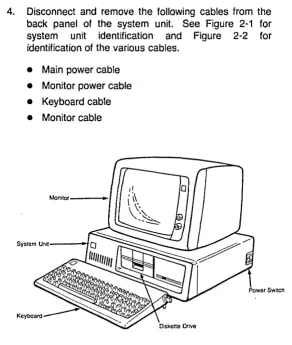
4. Disconnect and remove the following cables from the back panel of the system unit. See Figure 2-1 for system unit identification and Figure 2-2 for identification of the various cables.
• Main power cable
• Monitor power cable
• Keyboard cable
[image:46.398.73.366.47.392.2]• Monitor cable
o
o
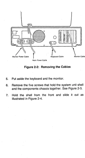
[image:47.406.51.348.41.587.2]Monitor Power Cable Keyboard Cable Main Power Cable
Figure 2-2: Removing the Cables
5. Put aside the keyboard and the monitor.
6. Remove the five screws that hold the system unit shell and the components chassis together. See Figure 2-3.
Cover Screws
Figure 2-3: Removing/Replacing the Shell Screws
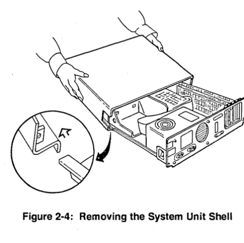
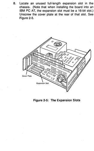
8. Locate an unused full-length expansion slot in the chassis. (Note that when installing the board into an IBM PC AT, the expansion slot must be a 16-bit slot.) Unscrew the cover plate at the rear of that slot. See Figure 2-5.
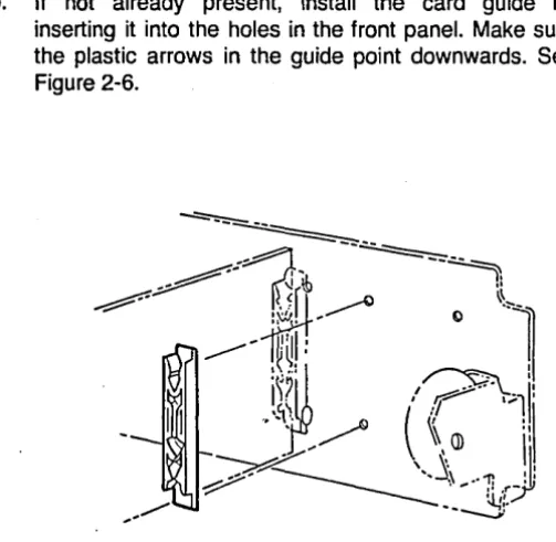
9. If not already present, install the card guide by inserting it into the holes in the front panel. Make sure the plastic arrows in the guide point downwards. See Figure 2-6.
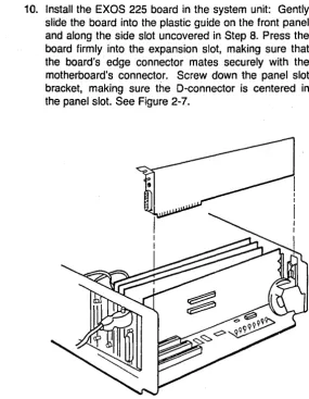
10. Install the EXOS 225 board in the system unit: Gently slide the board into the plastic guide on the front panel and along the side slot uncovered in Step 8. Press the board firmly into the expansion slot, making sure that the board's edge connector mates securely with the motherboard's connector. Screw down the panel slot bracket, making sure the D-connector is centered in the panel slot. See Figure 2-7.
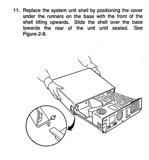
11. Replace the system unit shell by positioning the cover under the runners on the base with the front of the shell tilting upwards. Slide the shell over the base towards the rear of the unit until seated. See Figure 2-8.
12. Replace the five cover screws. See Figure 2-3.
13. Replace the following cables that were removed in Step 4:
• Main power cable • Monitor power cable
• Keyboard cable
• Monitor cable
14. Attach the male end (the end with locking posts) of the transceiver drop cable to the D-connector of the EXOS 225 (which is now accessible from the outside of the PC) and secure it by moving the slide latch as shown in Figure 2-9.
---P~il'
sh to close
___ --
I
TrTI1~
i
i'I'!I:',I!!
I
'~'II
: II: I Iii
J
: I
J9
_
,,~
J
-:;:;::--
15. Attach the female end (the end with slide latch) of the transceiver drop cable to the transceiver on the network.
Following Step 15, the installation of the EXOS 225 Ethernet Network Analyzer board into the PC and its connection to the network are complete. You are now ready to run the diagnostics, which are described in the next section.
2.2.2. Running the INSTALL Program and Diagnostics
The EXOS 225 hardware diagnostics and installation diskette contains the INSTALL program and diagnostics. The INSTALL program sets up various board configuration parameters by reading data from the configuration file; you can also supply these parameter values interactively. The program also runs diagnostics, -which are divided into two sets: one set is executed by the host PC; the other is executed by the 80186 CPU on the EXOS 225. The diagnostics exercise the on-board RAM, the 82586 Ethernet controller, the Ethernet serial interface chip, the connected transceiver, and the on-board Ethernet PROM. In addition, the diagnostics run three interrupt tests.
Note that as supplied from Excelan, the hardware diagnostics and installation diskette is write-protected. You should not remove the write protection.
The step-by-step procedure for running the diagnostics is given below. Naturally, before running the diagnostics, the EXOS 225 must have been installed as described in Section 2.2. Also, the EXOS 225 must be connected to the network through a transceiver and transceiver cable; otherwise, the diagnostics will fail.
1. Boot your system from ~OS. (The LANalyzer software operates under DOS Version 2.0 or later.)
If not already present, create the system file CONFIG.SYS with the following entry and then reboot the system.
DEVICE =ANSI.SYS
3. I nsert the EXOS 225 hardware diagnostics and installation diskette into drive A.
4. Enter the following command to input configuration information prior to running the diagnostics. Note that following Step 7, the configuration information is saved to the configuration file on the currently logged drive (drive C, the hard disk).
C> A:INSTALL
You will be prompted for the directory path (refer to Step 5) and for configuration information (refer to Step 6) if you have not previously installed the board and entered this information. If you have already entered some of the information, you will be prompted only for what the system needs.
5. If the configuration file is not already present on the hard disk, you will be prompted to enter the directory path as follows. Enter '\xln" as shown and then press Return.
Please enter the directory path where you wish the Excelan support software to be located: \Xln
You will then be prompted to confirm your entry, as follows. Enter a "y" response, as shown, and then press Return.
The path for Excelan software will be : \Xln Is this Ok (yes or no)? y
proper values. Note that the values for IOBASE and MEMBASE are given in hexadecimal. If you enter numbers for these values, you must append an "h" to the number (for example, 302h). Refer to Section 2.2.3 for information on entering other values.
Please enter monitor type
(M for monochrome, C for color): Please enter the value for IOBASE
(default [310h]):
Please enter the value for MEMBASE (default [AOOOh]):
Please enter the value for SIGNAL (default [2]):
7. At this point, the system displays the following messages:
Checking the installation of the EXOS 225 board. EXOS 225 diagnostics started
The system then begins running the diagnostics.
When the diagnostics are running, the screen shows various test names, associated parameters, and a zero error count for each test. For each test, the test data and status flash in the lower part of the screen.
Finally, one of the following messages appears at. the bottom of the screen:
Tests completed: PASSED Tests completed: FAILED
This message is followed by the DOS prompt, indicating that control has returned to the operating system.
If the diagnostics pass, the EXOS 225 is healthy and has been installed correctly. You can now install the LANalyzer software, as described in Section 2.3.
At the conclusion of Step 7, the configuration information entered in Step 6 is written to the file \XLN\HARDWARE\EXCELAN.HDW on the currently logged drive, that is, the hard disk. A detailed description of the configuration file is provided in Appendix B.
2.2.3. Reconfiguring the EXOS 225
As shipped from the factory, the EXOS 225 is configured for use in the PC you ordered it for. The following default values are set for all boards, regardless of the PC type .. These defaults can be changed as described in Sections 2.2.3.1 through 2.2.3.4. (Note that the parameters discussed in these sections are the only ones that can be changed while maintaining compatibility with the LANalyzer software supplied by Excelan.)
Memory: AOOOO - AFFFF (hex)
I/O space: 310 - 317 (hex)
I nterrupt: Level 2
In addition, the EXOS 225 board can be configured to operate with either an Ethernet Version 1.0 transceiver or and Ethernet Version 2.0/1EEE 802.3 transceiver. Configuring the board in this way is described in Section 2.2.3.5.
CAUTION
2.2.3.1. Changing the Host
If the board is to be installed in a different host from the one for which you ordered the LANalyzer kit, the board should be jumper-reconfigured as described in Table 2-1. Then the configuration file modified either by editing or by running the I NSTALL program.
Table 2-1: Jumper Configuration for Different Hosts
Host PC
IBM PC XTor COMPAQ PLUS
IBM PC AT or COMPAQ 286
Jumper Configuration
J6-1 through J6-8 J7
J10 (2-3)
J14,J15,J16 J17,J18,J19
J6-1 through J6-8 J7
J10(1-2) J14,J15,J16 J17,J18,J19
In Out In In In
2.2.3.2. Changing the Memory
The EXOS 225 uses a 64-Kbyte block of the PC's memory address space. The default block is AOOOO-AFFFF (hex). The memory block, which must be on a 64K boundary, can be changed by reconfiguring jumpers J8 and J9 (refer to Table 2-2). The configuration file should then be modified either by editing or by running the INSTALL program.
Table 2-2: Jumper Configuration for Different Memory Blocks
Memory Block (Hex)
~80000-8FFFF
90000-9FFFF AOOOO-AFFFF* BOOOO-BFFFF
" Default setting
Jumper Configuration
J8 J9
In Out
In Out
2.2.3.3. Changing the I/O Space
The EXOS 225 uses a block of eight addresses in the PC's 1/0 space. The default block is 310-317 (hex). If necessary, a different 1/0 block can be selected by reconfiguring the jumpers in J11 as shown in Table 2-3. The configuration file should then be modified either by editing or by running the INSTALL program.
Table 2-3: Jumpers for I/O Address Configuration
I/O Block Jumpers
(Hex) J11-1 J11-2 J11-3 J11-4 J11-5
300-307 In In In In In
308-30F In In In In Out
310-317* In In In Out In
318-31F In In In Out Out
320-327 In In Out In In
328-32F In In Out In Out
330-337 In In Out Out In
338-33F In In Out Out Out
340-347 In Out In In In
348-34F In Out In In Out
350-357 In Out In Out In
358-35F In Out In Out Out
360-367 In Out Out In In
368-36F In Out Out In Out
370-377 In Out Out Out In
378-37F In Out Out Out Out
2.2.3.4. Changing the Interrupt Level
The EXOS 225 uses one interrupt level on the PC. The factory setting is interrupt level 2, which is set by the presence of jumper J12-6. If this causes any conflict with the PC's configuration, the interrupt level can be changed to any level from 2 to 7. To change the interrupt level, install the applicable jumper as shown in Table 2-4. The configuration file should then be modified to reflect the change.
Table 2-4: Jumpers for Selecting the Interrupt Level
* Default
To Select Interrupt Level
2*
3
4
5
6
7
2.2.3.5. Selecting the Transceiver Type Install Jumper
J12-6 J12-1 J12-2 J12-3 J12-4 J12-5
As shipped from the factory the board is configured to run with an Ethernet Version 1.0 transceiver. The EXOS 225 board can a'iso be configured to operate with an Ethernet Version 2.0 or IEEE 802.3 transceiver.
When configured to operate with a Version 2.0 or IEEE 802.3 transceiver, the SQE test is enabled. Also, when in this mode, the output is AC-coupled; that is, the idle voltage is zero.
The transceiver configuration is defined by jumper J5. If this jumper is present, the board is in Version 1.0 mode (the factory setting). If this jumper is absent, the board is in Version 2.0IlEEE 802.3 mode.
2.3. LANALYZER SOFTWARE INSTALLATION
After the EXOS 225 board has been installed in the PC and the PC connected to the network as described above, the LANalyzer software is installed. The LANalyzer software is found on the system software diskette.
Note that your PC must be running DOS Version 2.0 or later in order to install and use the LANalyzer software.
Also note that as supplied from Excelan, the system software diskette is write-protected. You should not remove the write protection.
2.3.1. Installation Procedure
The following is a step-by-step procedure for installing the LANalyzer software on your PC. (In the description of the procedure, it is assumed that no problems are encountered. If any problem is encountered. the system displays an error message. Refer to Section 2.3.2 for details.)
1. Make sure that the EXOS 225 board has been installed in your PC and that the PC has been connected to the network, as described in Section 2.2.
2. Ensure that no floppy diskette is installed in drive A (or drive 8, if present) so that the system boots from the hard disk (drive C).
4. Insert the LANalyzer system software diskette into drive A of your PC.
5. Type the following command:
C> A:INSTALL
This initiates execution of the INSTALL program, which installs the system software on the hard disk.
After some time, the system displays the following message:
Please enter the directory path where you wish the command files to be placed.
This directory path should be included in the MS-DOS PATH command.
6. Enter the directory path as prompted.
The system then prompts you to confirm the directory pathname:
The path for the command files will be: directory_name Is this Ok (yes or no)?
Type y if directory_name is correct. Type n if it is incorrect; the system then reprompts you for the directory path.
After several moments, the system may display the following two lines, which you should ignore.
C>ECHO OFF
Unable to create directory
After about a minute, the system displays the following message and then returns to DOS (indicated by the prompt C>).
EXSOOOE software installation is complete. C>
8. Append the file \xLN\LANz\LANZRUN.BAT, which is supplied on the LANalyzer software diskette, to the AUTOEXEC.BAT system file so that the LANalyzer driver and EXOS 225 board code are loaded each time the PC is booted. This can also be accomplished by editing the AUTOEXEC.BAT system file to include the following two command lines:
LANZDRIV LANZLOAD
Following Step 8, you can begin using the LANalyzer software, as described in Chapter 3, Getting Started.
2.3.2. Error Messages
During the LANalyzer software installation process, you may encounter the following two error messages. Both may be displayed after you try to execute Step 5 above. The cause and cure for each problem is also indicated in the message.
• Cannot install software from an invalid software diskette. Please insert valid diskette and retype the INSTALL command.
• The Configuration File is not created/present on the system hard disk. Please install the hardware as described in the user manual; this will also create/update the Configuration file.
2.4. LANAL YZER PACKAGE SETUP
The LANalyzer package consists of a COMPAQ PORTABLE
286 computer in which the EXOS 225 board, the LANalyzer software, and DOS Version 3.x have been pre-installed and tested. The package also includes a transceiver and transceiver cable.
under which the LANalyzer software runs. Also, you may encounter problems in using your LANalyzer package at first because the hardware and/or software may have been damaged during . shipping. This section describes the modifications you can make to DOS. This section also explains the steps to take if the LANalyzer hardware and/or software do not appear to be working properly.
Before using the LANalyzer software, you may want to check that the factory-supplied AUTOEXEC.BAT file and the path are suitable for your needs. If they are not, you can modify them.
The AUTOEXEC.BAT file provided with LANalyzer contains the following commands. (This list also explains the purpose of each command.)
ECHO OFF
PATH= C:;C:\DOS;C:\LOCAL MODE SPEED=COMMON
EXCELAN=\XLN
LANZDRIV LANZLOAD LANZ
Disable screen echoing Set command search path Set operating speed for
COMPAQ 286
Set directory for Excelan support software Load LANalyzer driver Load EXOS 225 board code Invoke LANalyzer software
You can modify this file as necessary to meet your needs. However, if you want the LANalyzer software to be loaded and invoked each time the system is booted, the following lines must remain in the AUTOEXEC.BAT file:
PATH= C:;C:\DOS
MODE SPEED=COMMON EXCELAN =\xLN
LANZDRIV LANZLOAD
directories in the PATH command .. Refer to your DOS manual for information about the PATH command.
The directory specified in the command line "EXCELAN=directory_name" is the one that contains the Excelan support software. (The support software includes the object files for the LANalyzer screens [files with the extension .TPO] and the file MONITOR.86, which contains the EXOS 205 board code.) Actually, the support software resides in the directory \directory_name\LANZ. If you move this software to a different directory, you should modify this line in the AUTOEXEC.BAT file accordingly.
If any problem arises while using the LANalyzer system for the first time, you can attempt to correct it by performing one or more of the following steps, depending on the nature of the problem:
1. If you cannot invoke the LANalyzer software properly, check that the files CONFIG.SYS and ANSI.SYS are both present on drive C.
2. If you suspect a problem with the disk drive(s), run the DOS CHKDSK command. Refer to your DOS manual for information on this command.
3. If you suspect a problem with the EXOS 225 board, run the LANalyzer diagnostics. These are described in Section 2.2.2.
4. If the above steps are unsuccessful, re-install the LANalyzer software. This is described in Section 2.3.
3.1. INTRODUCTION
GETTING STARTED
The· LANalyzer EX 5000E system hardware and software are normally supplied in a kit form, which you must install into an IBM PC AT, IBM PC XT, or compatible PC. Once you have installed the hardware and software, as described in Chapter 2, you are ready to get started using the LANalyzer system.
As has been mentioned in Chapter 1, the main functions of the LANalyzer EX 5000E are to monitor traffic on a local area network, to generate traffic on the network, to capture and store packets (or packet segments), and to compile and save statistics about various network activities. These functions are realized by setting up and running tests.
A test is a program in which various control parameters are specified. The test parameters can be saved to a normal DOS file. (The LANalyzer software supplies the extension ".TST" to the test filename before saving it.) When a test is run, its results are displayed in real time .on the screen. The packets collected during a test reside in the EXOS 225 board memory and can be displayed immediately after a test concludes. Optionally, the collected packets can be saved to a DOS file.
This chapter, as the name suggests, is intended to get you started using the LANalyzer system. It provides a hands-on session which runs a test that is supplied as part of the system software. The chapter provides annotation at various stages of test execution.
manual, the following documentation convention is used to indicate execution of a command:
Press function key Fn (command)
or
Press Fn (command)
Both mean that you execute the command command by pressing function key Fn, where n is the number of the function key. For example, "Press function key F2 (run)" means that you should execute the run command by pressing function key F2. "Press F2 (run)" has the same meaning.
3.2. RUNNING THE DEFAULT TEST
A default test is provided as part of the LANalyzer system software. This test resides in the file \xLN\LANz\DEFAULT. The test accomplishes the following:
• Observes a" packet traffic activity on the network
• Collects all packets transmitted on the network
• Determines and displays the following on the screen:
- Total number of packets transmitted over the network
- Total number of bytes of packet data transmitted over the network
- Total number of packets broadcast (packets receivable by a" hosts on the network)
- Individual totals of packets observed with CRC, alignment, or length (short packet) errors
- Percent utilization of the network capacity
- Packet size distribution
3.2.1. Starting the Test
The following is a step-by-step procedure for running the default test.
1. Ascertain that the LANalyzer hardware and software have been correctly installed in the PC and that the PC has been correctly connected to the network. Ensure that the AUTOEXEC.BAT file has been updated, as described in Step 8 of the software installation (refer to Section 2.3.1).
2. Ensure that no floppy diskette is inserted in drive A (and drive B, if present). Then power up the PC.
3. When the prompt "C>" appears, invoke the LANalyzer software by entering the following command. Refer to Section 3.6 for a detailed description of all forms of invoking the LANalyzer software.
C> LANZ
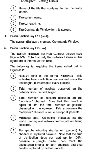
After a few moments the system displays the Edit Test screen (see Figure 3-1). Note that only the called-out items in this figure are of interest at this time.
The following list explains the items called out in Figure 3-1.