The Development of A New VTOL UAV Configuration For Law Enforcement
Zamri Omar
Department of Mechanical Engineering UTHM University, K.B 101, Pt.Raja
Johor, Malaysia Email: [email protected]
Cees Bil, Robin Hill
Wackett Centre for Aerospace Design RMIT University GPO Box 2476V
Melbourne, Australia
Email:{cees.bil, r.hill}@rmit.edu.au
Abstract:
This paper summarizes the ongoing project at RMIT University on the development of a new ducted-fan VTOL UAV configuration that mainly to aid the law enforcement activities. In this new configuration, several elements from fixed-wings and rotary-wings airplanes are merged together that
distinguish it from its class. The design objective is primarily to have a VTOL feature without
scarifying the high speed horizontal flight capability. It is a small, compact and light vehicle that makes it very effective to be used generally for law enforcement in the areas that other means are incapable. Discussions on the vehicle configuration, aerodynamics prediction, onboard systems, system simulation, and some of the planned works are briefly presented.
1. Introduction
Unmanned aerial vehicles (UAVs) are undoubtedly have great potential for supporting law enforcement operations in the areas that are difficult to reach by human or ground vehicles. The UAVs that are compact, high manoeuvrability, and have the capability of autonomous operation are effective to perform these duties. The conventional UAVs have three-dimensional mobility but have landing and takeoff restrictions, mission time limitations, and usually are demanding to operate. The typical problem encountered on most sites is the unavailable of ground space for the vehicle to take-off and land. In these restricted environments, the UAVs that have vertical take-off and landing (VTOL) capability offer some distinct operational advantages.
In this paper, a new UAV configuration has been developed that shows great promise for aiding law enforcement personnel. This UAV concept uses a ducted- fan VTOL, unmanned air vehicle to provide mobility to sensors and other payloads. On top of that, this unique design of UAV has the ability to perform transition maneuvers
between vertical and horizontal flights. This outstanding feature enables the UAV to capture the performance capabilities from both fixed-wing airplane and helicopter-like machines. This UAV system, with its onboard sensors, can assist in collecting evidence, performing long term surveillance or in assessing hazardous situations prior to engaging personnel. Also, this UAV is small enough to be transported in standard vehicles and which can easily be operated by law enforcement personnel.
2. Vehicle Configuration
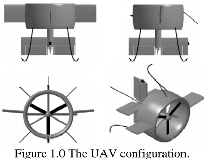
Figure 1.0 The UAV configuration.
Behind the location of the propeller,
[image:2.612.82.292.483.629.2]three aerodynamically shape stators are located and designed in such a way its angles are set so that they produce a rolling moment countering the torque of the propeller. This design eliminates the need of other countering torque mechanism for single propeller such as twin contra-rotating rotors which cause in weight penalty. At aft section is cross tail with independent control surfaces. System components and surveillance hardware are to be placed inside the wing duct and fuselage. At the outer section of the duct, two rectangular wings are attached in the y-axis direction, similar to typical airplane’s wings.
Figure 2.0 The flight modes.
A thin three-legged structure is attached to the body for take-off and landing purposes. Geometrically, this newly designed
UAV is about 0.5 m in both width and length and have approximately 5.18 kg for maximum take-off weight. The UAV will take-off vertically, then it be able to hover at the commanded altitude. From hovering condition, it will ramp in vertical forward to
gain enough speed, then rotates its body 90o
about y-axis to transit to enter the high speed in horizontal flight. In anytime during the flight, the reverse manoeuvre will bring the UAV to hover again. The UAV will have to be in this near static-orientation in order to perform task such as to have a high quality video transmitting on a particular location. The UAV also needs to be in hover again before it can land vertically as it does for take-off, but in reverse direction. A schematic diagram of the vehicle trajectory is shown in Figure 2.0.
3. Aerodynamics of the UAV
A computational fluid dynamics (CFD) analysis has been done to predict the aerodynamics of the UAV. The determination of various coefficients and parameters that establish the aerodynamics characteristics of the UAV through CFD method required several steps. It started with the development of the UAV geometric model using computer-aided-design (CAD) package, follows by grid generation around that CAD model. Then the airflow modelled around the UAV’s body that is to simulate the airspeed during the flight, and the respective data such as pressure distribution are recorded.
shows the swirling flow pattern, and pressure distribution around the tail and duct inlet sections.
Figure 4.0 Aerodynamics analysis.
4. Flight Control System
An intelligent system based on genetic algorithm and fuzzy logic is used as the vehicle controller. The diagrammatical representation of the overall control system is shown in Figure 4.0. The desired trajectory of the UAV is generated from the mission profile block that consists details of flight setting starting from UAV deployment, predefined waypoints/trajectory, navigations, and surveillance tasks to the recovery mission The commanded signals to the UAV control surface that determine vehicle’s attitude and trajectory are generated through a rule-based fuzzy logic control (FLC).
Genetic algorithm is embedded in the controller that is to be used at appropriate level for optimization of the fuzzy logic controller’s parameters. This is to find the optimal solution for the controller to respond on any specific flying condition such as to obtain the optimum shapes of membership functions of FLC during the transition from vertical to horizontal flight. The gathered information from the UAV’s states are fed to the controller, thus generates the system’s error needed for the feedback control system loop.
text
101010 110000
UAV Intelligent Control
[image:3.612.76.294.139.293.2]UAV position & orientation Mission Profiles
Figure 4.0 Intelligent flight control system.
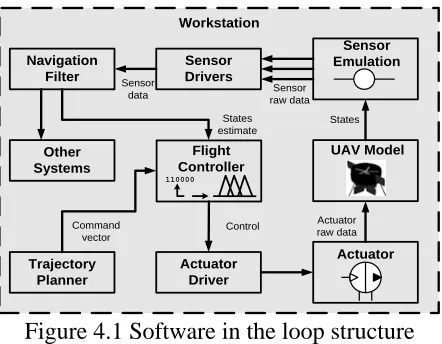
The software-in-the-loop (SITL) simulation which normally run on the desktop is a crucial tool that provides the user with the familiarization of the overall system operation. It also at this stage the debugging and modifying on any system parameters should be done. Figure 4.1 shows the SITL diagram of the UAV system. The un-compiled software source code, which normally runs on the onboard computer, is compiled into the simulation tool itself, allowing this software to be tested on the simulation host computer. This allows the flight software to be tested without the need to tie-up the flight hardware.
110000
UAV Model Flight
Controller
Actuator Actuator
Driver Sensor Drivers
Sensor Emulation Navigation
Filter
Trajectory Planner
Other Systems
States Sensor raw data Sensor
data
States estimate
Control Command
vector
Actuator raw data
Workstation
Figure 4.1 Software in the loop structure
5. Onboard System Architecture
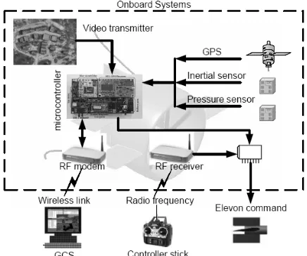
[image:3.612.333.554.481.653.2]control station (GCS) and the interconnections between the two. Figure 3.0 shows the schematic diagram of this system. The heart of the onboard system is a micro-controller, along with sensors and actuators, and communication devices that allows the functionality of autonomous control system. The on-board sensors include angular rate sensors for three axes, accelerometers for three-axes, a three-axis magnetic compass, a GPS sensor, an engine RPM sensor, absolute and differential pressure sensor, battery voltage and temperature sensors.
Figure 3.0 The system architecture
The micro-controller provides data acquisition, processing, and communication with the ground station. Although the fully autonomous operation of the UAV is possible, the system also been designed to enable the user to select between semi-autonomous or telemetry operation from ground control system. The UAV has two main remote communication links. The first link provides the main communication data between the UAV and the ground control station, that is for autonomous mode. The second link uses the standard communication channel between the remote control and the airplane, that is for manual mode. These two links are kept completely separate for safety reason. It is
because the manual mode using remote control acts as a failsafe mode which has to be available in anytime during the flight.
6. Concluding Remarks
The overall framework of processes, starting from the development of the UAV configuration, behaviour predictions, controller architecture, softwares and hardware requirement/applications and missions objectives have been discussed in substantially details. The findings in these works could direct the the research direction.
References
[1] Damien Poinsot, Conception Of An Uav Generic Mission System, 25th International Congress Of The Aeronautical Sciences, place 2006.
[2] Michael Livchitz, et.al, Development of an automated fuzzy-logic-based expert system for unmanned landing, Journal fo Fuzzy Sets and Systems, 145-159, 1993.
[3] Nicolas Grelaud et.al, Aerodynamic Design of a VTOL Ducted Fan UAV with
Surface Flow Control , 21st Bristol UAV Systems
Conference, April 2006.
[4] Michael P. Kontitsis, Nikos C. Tsourveloudis, and Kimon P. Valavanis, A UAV Based Automated Airborne Surveillance System.
[5] Kyuho Lee, Development of Unmanned Aerial Vehicle For Wildlife Surveillance, M.Sc Dissertation, University of Florida, 2004.
[8] Douglas Murphy, James Cycon,
Applications for mini VTOL UAV for law enforcement.
[9] Eric N. Johnson, Michael A. Turbe, Modeling, Control, and Flight Testing of a Small Ducted Fan Aircraft.
[10] Michael Gough, Design of a Mini
Tail-Sitter Ducted Fan VTOL UAV, B.Eng Project, RMIT University, 2005.
[11] Reed Siefert Christiansen, Design Of An Autopilot For Small Unmanned Aerial Vehicles, M.Sc Thesis, Department of Electrical and Computer Engineering, Brigham Young University, 2004.
[12] Kailash Kotwani, Ducted Fan or Shrouded rotor Aerodynamics and Its applications in VTOL Miniature Aerial Vehicles, Perhaps final year projet, got to google this ref,
[13] Derek Kingston, et.al, Autonomous Vehicle Technologies For Small Fixed Wing Uavs, AIAA labelled 2003, got to check.
[14] Ulrik B. Hald, et.al, Autonomous Helicopter:Modelling and Control, Project Report, Department of Control Engineering, Aalborg University, 2005.