Methods of Oil Drilling Sensor for High Temperature
and Vibrations
Tafiq Ahmed*, Mohammad Liton Hossain**
*
Electrical Engineering, University of Rostock, Germany * *
Electronics and Communication Engineering, Institute of Science and Technology, Bangladesh
DOI: 10.29322/IJSRP.8.11.2018.p8340 http://dx.doi.org/10.29322/IJSRP.8.11.2018.p8340
Abstract- Oil is any nonpolar chemical substance that is a viscous liquid at ambient temperatures. Oil drilling is a complex process that involves the drilling and pumping of oil from underground wells. There are some technologies for bringing oil to the earth surface. Oil drilling reaches usually a depth of 2 to 3 km. The drill heads containing a sophisticated sensor electronic, which is collecting data permanently during the drilling process. Due to the high friction temperatures up to 300°C may occur, only selected electronic components may resist for a few days. To measure the drill string vibrations shock-and-vibration sensors are used. Shock-and-vibration sensor is installed in measurement-while-drilling tools, logging-while drilling tools, and rotary steerable system [1]. Technologies working behind oil well drilling are developing. Electronic devices are used for oil well drilling having some high temperature fault and it's questionable for sustainability in huge vibrations. There is another problem in PCB. Most of the PCB made of brittle ceramic materials. This PCB substrate can’t sustain huge vibration. As a result, efficiency is decreasing and losses are increasing of oil companies. There for this research proposed a unique sensor which can work in high temperature for few days and also can sustain huge vibration
.
Index Terms- Band Gap, Chip Wafer, CMOS, LTCC, MCM, PCB
I. INTRODUCTION
T
As the oil industry looks to increase production from old field’s reservoirs, the vision of the digital oilfield is highlighted as a potential solution to many of the challenges presented by higher temperatures, higher pressures, longer tiebacks, and more expensive operations. We lead easy life because of the development of modern electronics. The drilling sensors are leading Big Oil’s mining of so-called big data, with some firms envisioning billions of dollars in savings over time by avoiding outages, managing supplies and identifying safety hazards. The main focus of oil companies is to make this ever-shrinking, increasingly complex electronics to operate at the hightemperatures, vibration, and extreme pressures encountered in ambient environments.
Many reputed company in the world already researched with oil drilling sensor. These company made their solutions by own. Here is some company name below
o Baker Hughes o Xilinx,Inc. o Schlumberger o Honeywell
II. EXISTING SOLUTIONS EVALUATION
There are so many solutions from different companies. Different companies are using different chip wafer, PCB Substrate, and Packaging material in order to get higher productivity for example:
A. Honeywell
American based company Honeywell Solid State Electronics Center (SSEC) are using different electronic devices for various purpose like example- HT83C51 (Microprocessor), HT6256 (SRAM), HT2007, HT2080, HT2160, HT2300, HT2400 (Gate array), HTCCG (Crystal clock generator). The operating temperature of these devices is in the range of 200º-300º C [5] This company use SOI technology for Chip Wafer. This company is also trying to develop SIC Chip Wafer which can be operating at 300º C [5].
http://dx.doi.org/10.29322/IJSRP.8.11.2018.p8340 www.ijsrp.org
Figure 1: SOI vs Bulk technology cross section [5]
For packaging this company uses a plastic housing [5]. The housing is cheap and can be mass produced. Investigated in this paper, Honeywell uses high temperature solder, Au88Ge12, industry name Indalloy IND.183 [5]. This solder is capable of working at around 300°C [6].
B. Xilinx,Inc.
Another popular American electronics company Xilinx manufactures sensors for oil wells technology. The chip used in oil drilling is known as XA6SLX45 which can operate in high temperature about 175º C [7]. This company is using wafer chip made of GaN or SiC [7]. GaN is used for its technological maturity though it is expensive in cost. On the other hand, the conductivity of SiC has better than other available semiconductors. Xilinx is using FR4 advance version popularly known as NELCO for PCB substrate which is also designed for high layer count PCB and high-speed digital applications [7]. NELCO is using for its extraordinary attribution such as- Pb (lead) free assemblies, high-speed low loss PCB, fine-line high layer PCBs, backplanes, communications and networking, manifold mounting and packaging etc [8].
For packaging technology, Ball Grid Array plastic package is mostly used [9]. BGA has numerous advantages, for instance, high density which means many hundreds of pin can be installed has lower thermal resistance between package and PCB, and due to low inductance leads signal are not distorted in high-speed electronic circuit [9].
Because of environmental concerns Pb-free soldering materials are the first and foremost for the industries. Pb is mixed with other solder material such as TIN(Sn). For the mechanical, electrical and thermal properties a viable solder material is used by Xilinx which is SnAgCu (96.5 Sn–3 Ag–0.5 Cu) with dispersion hardening technology. This technology has higher creep resistance and higher temperature sustainability [9].
C. Baker Hughes
One of the most respected producers of oil drilling sensors called Baker Hugher, have taken a direct approach to the problem
[image:2.612.41.296.59.217.2]which is they have wanted to substitute and use solutions which are currently available in the market hence easy to integrate. An important solution advised by the Engineers of Journal of Petroleum Technology (JPT) designed the sensors which can operate at the temperature of 180º C. Si is used as a chip wafer with SOI technology like Honeywell SSEC. Unlike Honeywell, for PCB substrate JPT Electronics is using LTCC (Low Temperature Co-fired Ceramic) as LTCC has good thermal conductivity [11].
Figure 3: Baker Hughes chip [10]
As we know Pb(lead) is unfriendly for environment. So, for soldering material with solid solution hardening technology JPT Electronics company uses PbSn [11]. For strengthening the pure material solid solution hardening alloy is used. This company is also using Pb-free soldering material Sn96Ag04 which is environment Friendly [11].
Baker Hugher is using Multichip Module (MCM) for housing which is generally an assembly contains a multiple number of chips and integrated circuit. MCM is also called hybrid integrated circuit [11].
III. EVALUATION & DISCUSSION OF PROBABLE SOLUTION
A. Chip Wafer
[image:2.612.323.568.67.170.2]The main foundation of circuit is chip wafer. It is necessary to focus on band gap energy of the semiconductor materials and effect of intrinsic carrier concentration due to temperature when choosing materials for chip wafer.
[image:2.612.314.567.327.464.2]B. Band Gap
First step is to consider band gap. Proposed system needs higher band gap energy and also higher conduction band. 6H-SiC is the best option for that. Those materials which have higher band gap and higher conduction band are suitable at room temperature. With the increase in temperature the band energy gap reduces. When the property is reduced it compromises electrical conductivity. The higher band gap is suitable for operating the sensor at a higher temperature [12]. If the band gap is too high then the material will not work at normal temperature. Now the most important thing is material should not choose only looking at high temperature operating point but also long temperature range [13]. Then this material will be efficient for the system.
C. Intrinsic Carrier Concentration
Second step is understanding the intrinsic carrier concentration of the semiconductor materials. The intrinsic carrier concentration is the number of electrons in the conduction band or the number of holes in the valence band in intrinsic material. This number of carriers depends on the band gap of the material and on the temperature of the material. The equation is
n = NcNve( −Eg
KT) ………….(1)
[image:3.612.34.592.59.283.2]Equation (1) shows effective density of states at valence and conduction band. Changing of temperature, causes the value of density change. For this, electrons travel from one electron band to another due to the gain of kinetic energy provided by the heat. In graph there is a relationship between normalized temperature and intrinsic carrier concentration. Lower the gradient of material the greater stability at high temperature.
Figure 4: Different semiconductors Intrinsic Carrier Density Vs. Temperature [17].
D. Identifying Best Semiconductor
Studying all types of semiconductor materials, proposed system can eliminate all semiconductor materials except GaN and 6H-SiC. It is possible to choose both GaN or 6H-SiC for chip wafer but 6H-SiC is the best choice. It has good stability at high temperature compared to GaN. 6H-SiC has huge operating temperature range. Adding to that the assembly technology maturity of SiC is better [16]. So 6H-SiC is the final choice for chip wafer in this proposed system.
Figure 5: Different semiconductors Intrinsic Carrier Density Vs. Temperature [17].
E. PCB Substrate Material
Another important part of packaging is PCB substrate. Before shorting out PCB substrate material it is very important to focus on: Substrate temperature resistivity, Shock and vibration absorb capability.
Materials
Band
Gap
(E
g)/eV
Operating
Temperature/°C
Density
at
Valence
band
(N
v)/cm
-3
x10
19Density at
Conduction
band
(N
v)/cm
-3x10
19Si
1.08
150
1.04
2.89
Ge
0.66
75
0.6
1.04
GaAs
1.42
350
0.7
0.05
6H-SiC
3.03
>600
2.9
8.5
[image:3.612.322.560.440.651.2]http://dx.doi.org/10.29322/IJSRP.8.11.2018.p8340 www.ijsrp.org
a. Direct Bonded Coper Substrate (DBC)
[image:4.612.304.585.69.328.2]DBC means Direct Bonded Copper and denotes a process in which copper and a ceramic material are directly bonded. Normally, DBC has two layers of copper that are directly bonded onto an aluminum-oxide (Al2O3) or aluminum-nitride (AlN) ceramic base. The DBC process yields a super-thin base and eliminates the need for the thick, heavy copper bases that were used prior to this process. Because power modules with DBC bases have fewer layers, they have much lower thermal resistance values [19].
Figure 6: DBC process flow [19]
Properties of DBC ceramic substrates:
• Good mechanical strength; mechanically stable shape, good adhesion and corrosion resistant [19].
• Excellent electrical insulation [19].
• Superb thermal cycling stability [19].
• The thermal expansion coefficient is close to that of silicon, so no interface layers are required [19].
• Good heat spreading [19].
Table-2: Comparison among DBC, LTCC and MCPCB [19]
PCB substrate
types
DBC
LTCC
MCPCB
Pull Strength
(Kg/cm
3)
>120
>50
>50
Meterial
99.99%
Cu
Ag+SiO
299.99%
Cu
Thickness (mm)
0.01-1.6
0.01
0.01-1.5
Current(A) (1mm
Width)
10 (0.3
mm
thickness)
0.3
(0.01mm
thickness)
10 (0.3
mm
thickness)
Dielectric
Strength(KV/mm)
>14
>14
<5
Reliability
>500
cycles
<200
cycles
<200
cycles
Maximum
Temperature (°C)
850
<500
<300
From the Table-2 it can easily find out the best one. For DBC the temperature is higher than others, Reliability is high compares to others and finally the strength is also very high comparison to LTCC and MCPCB.
b. Mechanical Protection
Though DBC is the best for PCB substrate but I also like to add some additional protection which is called mechanical protection for shock and vibration. Vibration may also cause mechanical failure in the housing itself. This is equally undesirable; a loosened screw, pin, or clip can lead to cascading failures that damage and even destroy the system. Elastomers and thermoplastic mounts can effectively reduce the likelihood of such an event by dampening these instead of transmitting the vibrations [20]. As insulation material, mineral wool (stone) can be used which can survive at the temperature up to 750º C [21].
IV. PACKAGING AND JOINING TECHNOLOGY
A. Packaging (Housing)
[image:4.612.45.257.215.522.2]www.ijsrp.org
[image:5.612.84.278.127.257.2]is necessary to identify operating temperature of materials. From the equation of homologous temperature, it can be easy to find out the operating temperature. The equation is
Figure 7: Outline of Packaging
𝑇
𝐻=
𝑇
𝑇
𝑚𝑒𝑙𝑡Here,
TH= Homologous temperature T= operating temperature Tmelt= Melting temperature
All metals have TH around 0.3-0.5 [22]. From the above equation I find out the operating temperature of Aluminum which is 330º C which is suitable to face the challenge of high temperature. The thermal expansion of Aluminum is larger comparing to the other metal. The coefficient of thermal
expansion of Al is 25.2 μm/m-°C [23]. It is also corrosion Resist metal. Aluminum is not brittle. Aluminum is lighter in weight compare to other material. So, considering all these strong side of Aluminum my choice is to use Aluminum instead of ceramic.
B. Joining Technology
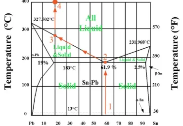
Soldering is the main concern of Joining technology. Mostly used solder alloy in high temperature is Pb-Sn. Melting point of Pb-Sn depends on the percentage of Pb and Sn of it’s combination. When the percentage of Pb is 95% and Sn is 5% normally the melting point of Pb-Sn is greater than 330º C [24].
But for oil drilling sensor, Pb-Sn might be used with solid solution hardening technology which improves the strength of the pure metal.
We all know that Pb is not environment friendly that is why we can also use Au-Sn. Though Au-Sn is expensive might be used for joining technique
.
Figure 9: Solder alloy Au-Sn High melting point [26].
Au-Ge and Au-Si might be the solution though these are expensive solder alloy which can perform at 300º C for 20 days. To increase strengthen of the material solid solution hardening technique can be used [27].
V. COMPARISON BETWEEN EXISTING SOLUTION AND SUGGESTING SOLUTION
Oil Company using their own solution to find out high temperature electronics fault and the effect of vibrations. It is clear that the existing solutions are well researched and successfully applied for oil drilling. The suggesting solution is theoretical analysis of some problems and solution is also theoretical. Comparison between the both can only possible in theoretical way. Considering temperatures, existing solution given by Baker Hughes and Xilinx are not good enough. So, the only company that is Honeywell is exists.
For chip wafer, Honeywell used SOI technology and suggested solution is 6H-SiC. It is well documented that with increasing of Si wafer the quality collapse with temperature. That is why 6H-SiC is better option for chip wafer.
Honeywell uses ceramic nature for PCB substrate. The suggesting solution is also ceramic nature but Reliability of DBC is very high comparing to the others ceramic substrate. There is also used mechanical protection for Suggested solution. So, comparing both suggesting solution is better.
Housing technology, the company used plastic packaging which cannot operate at high temperature like more than 300º C. Suggesting solution is Aluminum which is used with insulation layer can be a better idea.
[image:5.612.314.575.143.326.2] [image:5.612.63.248.580.708.2]http://dx.doi.org/10.29322/IJSRP.8.11.2018.p8340 www.ijsrp.org
soldering alloy can easily integrate with PCB. Both have high-temperature superiority.
VI. MANAGEMENT OF COST
Table-3: Cost management [29,30,31,32]
VII. CONCLUSION
Oil Company always trying to find out stable and efficient solutions to overcome all drawbacks. They redesign the electronic assembly so that the system can be stable for a limited time but it is not easy to find a stable solution against high temperature and high vibration. This research is trying to find out some probable solutions, only analyzing these problems theoretically. This research tried to find out something new and stable solutions which are not used in market. Before using these solutions multiple and proper experiments are needed.
APPENDIX
Appendixes, if needed, appear before the acknowledgment.
ACKNOWLEDGMENT
At first all thanks goes to almighty creator who gives me the opportunity, patients and energy to complete this study. I would like to give thanks to Prof. Dr Mathias Nowottnick. I have found always immense support from them to keep my work on the right way. His door was always open for me, when I have got myself in trouble. Finally, I must express my very profound gratefulness to my parents for providing me with constant support and encouragement during my years of study and through the process of analyzing and writing this paper. This accomplishment would not have been possible without them. Thank you
REFERENCES
[1] Bowler, A., Harmer, R., Logesparan, L., Sugiura, J., Jeffryes, B. and Ignova, M. (2016).
Continuous High-Frequency Measurements of the Drilling Process Provide New Insights Into Drilling-System Response and Transitions Between Vibration Modes. SPE Drilling & Completion, 31(02), pp.106-118.
[2] R.Lowther,W.Morris,D. Gifford,D.Duff,R. Fuller,J.Salzman. Latchup Immunity Temperature Bulk CMOS Device. Available at:
https://www.voragotech.com/sites/default/files/whitepapers/110715_HiTEN _Paperfinal_watermark%26addTI.pdf
[3] PCB materials. Available at: https://www.pcbcart.com/pcb-capability/pcb-materials.html
[4] Exploration & Production. (2013). Downhole electronics: How hot can you go?. [online] Available at: http://www.epmag.com/downhole-electronics-how-hot-can-you-go-708311 [Accessed 22 Jul. 2018]. [5] G oetz, J. (1998, October), High Temperature Electronics for Sensor Interface and Data Acquisition. Expo(pp.1-23)
[6] Chidambaram, V., Yeung, H. B., & Shan, G. (2012). Reliability of Au-Ge and Au-Si eutectic solder alloys for high-temperature electronics.Journal of electronic materials,41(8), 2107-2117.
[7] XA Spartan-6 Automotive FPGA Family Overview. [online] Available at: https://www.xilinx.com. (2012). [Accessed 22 Jul. 2018].
[8] Parkelectro.com. (2010). Nelco FR4 Epoxy Electronic Materials. [online] Available at: http://www.fastturnpcbs.com/upfile/2014102214381244.pdf [9] En.wikipedia.org. (2017). Ball grid array. [online] Available at: https://en.wikipedia.org/wiki/Ball_grid_array#Advantages [Accessed 22 Jul. 2018].
[10]Beckwith, R. (2013). Downhole electronic components: Achieving performance reliability.Journal of Petroleum Technology,65(08), 42-57. [11] Beckwith, R. (2013). Downhole electronic components: Achieving performance reliability. Journal of Petroleum Technology, 65(08), 42-57. [12] Temperature dependence of the energy bandgap.ecee. colorado. edu. Van Zeghbroeck, B. J. (1996).
[13] Solid state electronic devices. Prentice-Hall. Streetman, B. G., & Banerjee, S. K. (2005).
[14] Werner, M. R., & Fahrner, W. R. (2001). Review on materials,
microsensors, systems and devices for high-temperature and harsh-environment applications.IEEE Transactions on Industrial Electronics,48(2), 249-257. [15] Shenai, K., Scott, R. S., & Baliga, B. J. (1989). Optimum semiconductors for high-power
electronics.IEEE transactions on Electron Devices,36(9), 1811-1823. [16] Choyke, W. J., Adlerstein, M. G., Cuomo, J. J., Foyt, J. A. G., Hu, E. L., Kimerling, L. C., ... & Turlik, I. (1995). Materials for High-Temperature Semiconductor Devices.
[17] Kemerley, R. T., Wallace, H. B., & Yoder, M. N. (2002). Impact of wide bandgap microwave devices on DoD systems. Proceedings of the IEEE,90(6), 1059-1064.
[18] Semiconductors for High Temperature Electronics", in HITEN. [19] Better thermal management and smaller footprient in thin film, thick film design. Available at: https://metallized-ceramic.ready-online.com/dbc.html [20] David Askew, Mouser Electronics. Vibration Protection of Electronic Components in Harsh Environments. Available at:
https://eu.mouser.com/applications/harsh-environment-vibration-protection/ [21] Competition Commission Alternatives to Glass Mineral Wool. Available at:
https://web.archive.org/web/20090902213111/http://www.competition-commission.org.uk/inquiries/completed/2004/superglass/glass_wool_report.pdf [22] Gibeling, J. C. (2000). Creep Deformation of Metals, Polymers, Ceramics, and Composites.ASM Handbook,8.
[23] Elmer, J. W., Olson, D. L., & Matlock, D. K. (1982). Thermal expansion characteristics of stainless steel weld metal. WELDING J.,61(9), 293. [24] Solder Properties. Available at:
http://www.rfcafe.com/references/electrical/solder.htm [25] The origin of magmas. Available at:
http://www.indiana.edu/~geol105/images/gaia_chapter_5/origin_of_magmas.htm
Remark Chip
wafer
PCB
Substrate
Packaging
Joining
Name
6H-SiC
Direct
Bonded
Copper
(DBC)
Aluminum
a)
Pb-Sn
b)
Au-Sn
Price
per
Unit
$10-1000
[28]
$0.5-8
[29]
$2000-4200 /
Metric ton
[30]
a) $2-2.7/ Roll
[31]
b) $125/ Piece
[26] A wafer-level Sn-rich Au–Sn intermediate bonding technique with high strength. Available at: http://iopscience.iop.org/article/10.1088/0960-1317/23/9/095008
[27] Chidambaram, V., Yeung, H. and Shan, G. (2012). Reliability of Au-Ge and Au-Si Eutectic Solder Alloys for High-Temperature Electronics. Journal of Electronic Materials, 41(8), pp.2107-2117.
[28] www.alibaba.com. (2017). Silicon Carbide Sic Semiconductor Wafer - Buy Semiconductor Wafer,Sic Semiconductor Wafer,Sic Wafer Product on Alibaba.com. [online] Available at:
https://www.alibaba.com/product-detail/Silicon-Carbide-SiC-semiconductor-wafer_60611370099.html? spm=a2700.7724857.main07.1.73f973f0L5qT9q&s=p [Accessed 22 Jul. 2018].
[29] https://www.alibaba.com/product-detail/HIGH-INSULATIVITY-Ceramic-
Direct-Bond-Copper_60374886910.html?spm=a2700.7724838.2017115.1.3d67435cmQwLQh [30] www.alibaba.com. (2017). Aluminium Coil In Roll For Building And Vehicl Construction And Electronics Product 1xxx 3xxx 5xxx - Buy 5xxx,3xxx,6061 Product on Alibaba.com. [online] Available at: https://www.alibaba.com/product-
detail/Aluminium-Coil-in-Roll-for-Building_60582806278.html?spm=a2700.7724838.2017115.1.TjOnHm&s=p
[31] www.alibaba.com. (2017). High Melting Point Tin Lead Solder Wire Sn5/pb95 - Buy Solder,Tin Solder, Super Solder Wire Product on Alibaba.com. [online] Available at:
https://www.alibaba.com/product-detail/high-melting-
point-tin-lead-solder_1351793653.html?spm=a2700.7724838.2017115.29.GMcqQI
[32] www.alibaba.com. (2017). Solder Wire / Ribbon / Strip Gold Tin Foil Ausn Alloy - Buy Solder Wire,Gold Tin Foil,Ausn Product on Alibaba.com. [online] Available at: http://liquids.seas.harvard.edu/alexey/gold.html
AUTHORS
First Author – Tafiq Ahmed, , M.Sc in Electrical Engineering in University of Rostock, Germany;
Email: [email protected]
Second Author – Mohammad Liton Hossain, M.Sc in Computational Science and Engineering, University of Rostock, Germany, Lecturer at Institute of Science and Technology (IST), Bangladesh.
![Figure 3: Baker Hughes chip [10]](https://thumb-us.123doks.com/thumbv2/123dok_us/9064288.978252/2.612.41.296.59.217/figure-baker-hughes-chip.webp)
![Figure 4: Different semiconductors Intrinsic Carrier Density Vs. Temperature [17].](https://thumb-us.123doks.com/thumbv2/123dok_us/9064288.978252/3.612.322.560.440.651/figure-different-semiconductors-intrinsic-carrier-density-vs-temperature.webp)
![Figure 6: DBC process flow [19]](https://thumb-us.123doks.com/thumbv2/123dok_us/9064288.978252/4.612.45.257.215.522/figure-dbc-process-flow.webp)