ISSN 2250-3153
CFD Analysis of Mass Flow under Non-Uniformity
constraints through Heat Exchanger
Kirti Onkar Prajapati1, Harshwardhan Uddhage2, Sanjay Kumbhare3, Krishna Kumar Thakur4 1
M.Tech Research Scholar, Dept. of Thermal Engg., PCST, Bhopal, [email protected] 2
M.Tech Research Scholar, Dept. of Thermal Engg., PCST, Bhopal, [email protected] 3
Assistant Professor, Dept. of Thermal Engg., PCST, Bhopal, [email protected] 4Associate Professor, Dept. of Thermal Engg., PCST, Bhopal, [email protected]
Abstract- Heat exchanger is mainly associated with transfer heat from one fluid to another fluid either in direct contact with each other or separated by wall. The heat exchangers characteristics are concerned with the rate of heat transfer between the fluids with assuming the flow to be uniform throughout the core of the exchanger. But in actual practice it is usually the flow Non-uniformity that occurs and adversely affects the Heat Transfer rate and heat exchange properties of the heat exchanger. The major non-uniform flow is caused due to poor header design or restrictions in flow at microscopic level as a result of manufacturing operations on the surface. The CFD analysis of Heat exchanger is achieved considering the concept of Viscosity induced flow Non-Uniformity through the exchanger tubes. With the application of Computational Fluid Dynamics package FLUENT relative analysis pertaining to Non-uniform flow is carried out. The matter of interest of this paper is to analyze the heat transfer related to two mean temperatures namely cross-sectional and adiabatic mean temperature.
Index Terms- Algorithm, Analysis, CFD, Convergence, Fluent, Gambit, Grid, Heat flow, Models, Non-uniform, and Solver.
I. INTRODUCTION
Shell-and-tube heat exchangers are the most versatile type of heat exchanger. They are used in many industrial areas, such as power plant, chemical engineering, petroleum refining, petrochemicals industries, food processing, paper industries, etc. Shell and tube heat exchangers provide relatively large ratios of heat transfer area to volume and weight and they can be easily cleaned. They have greater flexibility to meet any service requirement. The shell-and-tube heat exchangers consist of a bundle of tubes enclosed within a cylindrical shell. One fluid flows through the tubes and a second fluid flows within the space between the tubes and the shell. Heat exchangers in general and tubular heat exchangers in particular undergo deterioration in performance due to flow non-uniformity. The design and Analysis of Heat Exchanger is carried out with a major consideration in terms of Mass flow of the fluid to be distributed uniformly at the inlet of the exchanger on each side that is, fluid side and throughout the core. But, in actual practice, the flow Non-Uniformity is more common and significant which reduces the desired heat exchanger performance. Non-uniform flow is defined as of the mass flow rate on one or both sides in any of heat exchanger
ports and in the heat exchanger core. The prime non-uniform flow occurs at the macroscopic level. The overall flow non-uniformity is independent of local geometry of the heat transferring surface. Flow non-uniformity can be induced by basic geometry, operational conditions, passage to passage flow imperfections and instability. One class of flow non-uniformity is a result of geometrically non-ideal fluid flow passages or non-ideal exchanger inlet/outlet manifold, nozzle, and referred as geometry induced flow non-uniformity.
Investigation is carried out to study the cross sectional mean temperature and adiabatic mean temperature profiles in the computational domain, tubular single pass heat exchanger for flow Non-Uniformity or uniform mass flow distribution on tube side and ideal plug flow on shell side. It is investigated that for uniform mass flow distribution on tube side and ideal plug flow on shell side, there is no difference between the cross-sectional mean temperature and adiabatic mean temperature. For the analysis purpose a shell and tube heat exchanger is considered with pure axial flow on the shell side and non-uniformity on the tube side.
II. NEED OF ANALYSIS
ISSN 2250-3153
a considerable amount of time and effort. Therefore, it is usually necessary to minimize the number of simulation runs needed for optimization. However, few authors studied the fluid flow Non-Uniformity using the computational fluid dynamics (CFD) simulation technique, especially the effects of the configuration of header and distributor on the flow distribution in plate-fin heat exchangers. CFD simulation technique can provide the flexibility to construct computational models that are easily adapted to a wide variety of physical conditions without constructing a large-scale prototype or expensive test rigs. Therefore, CFD can provide an effective platform where various design options can be tested and an optimal design can be determined at a relatively low cost.
The objective of study is to provide more complete understanding of Flow Non-Uniformity in tubular heat exchanger by studying area weighted and mass weighted temperature profiles for Non-Uniformity without back flow and Non-Uniformity with back flow. And comparison of average temperature profiles of flow Non-Uniformity with the average temperature profiles of uniform mass flow distribution. The FLUENT codes were used for the simulations. The simulation procedure with the required conditions of operation is started with pre-processing. The computational mesh was generated using tetrahedral elements. In order to accurately resolve the solution fields in the high gradient regions, the grid was stretched. The discretization scheme was first order upwind scheme.
III. MODELING USING GAMBIT
Depending on the problem, the geometry can be created and meshed with a careful consideration on the size of the computational domain, smoothness of cells, shape, and density. More efficient results are obtained by considering the proper physical models. Several independent variables are generally encountered in the design of a thermal system. A workable design is obtained when the design, as represented by a selection of values for these variables, satisfies the given requirements and constraints. The same variables, considered over their allowable ranges, indicate the boundaries of the
Fig.1 Outline of a Conventional Heat Exchanger
domain in which the optimal design is sought.A change in the conceptual design is undertaken at the feasible design stage, not during optimization, since one would proceed to optimize the system only after a workable design has been obtained. There is limitation for variation in design at analysis level however the model may be improved due to inputs from the simulation.
The generation of grid is carried out for corresponding boundary constraints and grid meshing values. The possibility of using simplified 3D models of recurrent segments of the heat exchanger in order to consider the non-uniform mass flow and simulate the flow throughout the length of exchanger. A very important factor when creating the numerical model is division of a real heat exchanger into current segments. This process should be dependent on the heat exchanger construction. In the analyzed case the possibility of utilizing Finite volume method is used for model validation taken into account.
There are two ways of generating a mesh. Gambit calls them 'top down' or 'bottom-up' in the user manuals. These instructions are bottom-up. You will create vertices upon which the edges will be built upon. Connecting edges will create a face. Connecting faces will create a volume (3D). Once the face or volume is created, a mesh can be generated on it.
Fig.2 Heat exchanger with outlet and inlet temperature Variables
ISSN 2250-3153
Fig.3 Meshed model using Computational Domains
A complexity for application of the numerical methods in tubular heat exchangers is the fact that one is faced with a complex geometry of the flow configuration. Moreover, several geometric parameters directly effecting on the enhancement of heat transfer
IV. GOVERNING EQUATION
The basic set of equations was added to this numerical mesh to complete the numerical model, and the complete unsteady Navier-Stokes and the energy equation for incompressible fluid with temperature-dependent properties. Computational fluid dynamics (CFD) is one of the branches of fluid mechanics that uses numerical methods and algorithms to solve and analyze problems that involve fluid flows. The fundamental basis of any CFD problem is the Navier-Stokes equations, which define any single-phase fluid flow. These equations can be simplified by removing terms describing viscosity to yield the Euler equations. Further simplification, by removing terms describing vortices yields the full potential equations.
Finally, these equations can be linearized to yield the linearized potential equations.
Continuity equation (mass balance):
𝜕
𝜕𝑥𝑖 (𝜌𝑈𝑖) = 0
Momentum equation:
𝐷(𝜌𝑈𝑖)
𝐷𝑡 =−
𝑑𝜌 𝑑𝑥+
𝜕 𝜕𝑥𝑖�𝜇 �
𝜕𝑈𝑖
𝜕𝑥𝑗+
𝜕𝑈𝑗
𝜕𝑥𝑖�� −
2𝜇𝜕𝑢𝑘
3𝜕𝑥𝑘 𝛿𝑖𝑗
Energy balance equation:
𝐷(𝜌𝑇)
𝐷𝑡 =
𝜕 𝜕𝑥𝑖��
𝜇 𝑃𝑟+
𝜇𝑡
𝑃𝑟𝑖�
𝜕𝑇 𝜕𝑥𝑖�
Momentum equation - Navier-stokes equation:
𝜕
𝜕𝑥𝑗�𝜌𝑢� �𝚥 = 0
𝜕
𝜕𝑥𝑗(𝜌𝑢� 𝑢𝚥�𝚤=−
𝜕𝑝̅ 𝜕𝑥𝑖+
𝜕 𝜕𝑥𝑗�𝜇
𝜕𝑢�𝚤
𝜕𝑥𝑗+𝜏𝑖𝑗�
The Navier-Stokes equations mentioned so far have been developed essentially for the flow of fluid to be considered under laminar flow regimes. However, in practical applications, the flow is almost always turbulent. To compensate for this fact a model needs to be utilized to simulate the existence of turbulence.
Governing equations in shell and tube heat exchanger with non-uniform flow in tube side:
In the shell-and-tube heat exchanger, a constant velocity of tube side fluid is usually assumed in all the tubes. Under the realistic assumption of plug flow inside each of the N tubes, the tube side equation given by Ranjit Kumar Sahoo, Wilfried Roetze,[1] is,
𝑑𝜃1𝑗
𝑑ξ +
𝑘 𝐴 𝑁⁄
(𝑊1⁄𝑁)�𝑊1𝑗⁄ �𝑊����1 �𝜃1𝑗− 𝜃2�= 0
Mass continuity equation:
𝜕𝜌
𝜕𝑡+𝑑𝑖𝑣(𝜌𝑢�⃗) = 0
X-component momentum equation:
𝜌 �𝐷𝑢𝐷𝑡�=𝜕(−𝑝𝜕𝑥+𝜏𝑥𝑥)+𝜕𝜏𝜕𝑦𝑦𝑥+𝜕𝜏𝜕𝑧𝑧𝑥+𝐹𝑥
Y-component momentum equation:
𝜌 �𝐷𝑣𝐷𝑡�=𝜕𝜏𝜕𝑥𝑥𝑦+𝜕�−𝑝𝜕𝑦+𝜏𝑦𝑦�+𝜕𝜏𝜕𝑧𝑧𝑦+𝐹𝑦
Z-component momentum equation:
𝜌 �𝐷𝑤𝐷𝑡�=𝜕𝜏𝜕𝑥𝑥𝑧+𝜕𝜏𝜕𝑦𝑦𝑧+𝜕(−𝑝𝜕𝑧+𝜏𝑧𝑧)+𝐹𝑧
Shell side equation is given as
𝑑𝜃2
𝑑ξ + 𝑁𝑇𝑈2�
1
𝑁� 𝜃1𝑗− 𝜃2
𝑁
𝐽=1
ISSN 2250-3153
The Case of NTU2 are as:-
1. For counter flow, NTU2 > 0
2. For concurrent flow, NTU2 < 0
3. For condensation and evaporation, NTU2 = 0
Turbulence is fundamentally the presence of velocity fluctuations of the mass of fluid within flow. It is characterized by random and scattered, three-dimensional motions of fluid particles in addition to the mean flow motion on the surface and within the core of heat exchanger.
V. NUMERICAL ANALYSIS
The Numerical analysis is achieved using the finite volume technique to yield a set of algebraic equations which could be solved by the algebraic multi grid solver of Fluent 13.1in an iterative manner by imposing the above boundary conditions. FLUENT is a computer program for modeling fluid flow and heat transfer in complex geometries.Constrained problems are quite common in the design of thermal systems. The equality constraints are largely due to the basic conservation principles for mass, momentum, and energy.However, in most practical cases, the numerical simulation of the system includes the conservation equations and other restrictions on the variables. All attempts are made to convert constrained problems into unconstrained ones so as to reduce the complexity. FLUENT provides complete mesh flexibility, including the ability to solve flow problems using unstructured meshes that can be generated about complex geometries with relative ease. Supported mesh types include 2D Triangular/ quadrilateral, 3D tetrahedral/ hexahedral/ pyramid/ wedge, and mixed (hybrid) meshes. FLUENT also allows you to refine or coarsen your grid based on the flow solution. All functions required to compute a solution and display the results are accessible in FLUENT through an interactive, menu-driven interface.
Case Consideration: - Single pass two channel shell and tube heat exchanger.
Dimensions of the exchanger:
Length of the exchanger (L) 550 mm
Width of the exchanger (b) 22 mm
Height of the exchanger (h) 28 mm
Tube diameter (d) 8 mm
Boundary conditions:
Channel number
Mass flow rate in (kg/sec)
Channel 1 5.439
Channel 2 2.745
Three-dimensional equations of mass, momentum and energy have been integrated over the control volume and the subsequent equations have been discretized over the control volume using the finite volume technique to yield a set of algebraic equations which could be solved by the algebraic multi grid solver of Fluent 12.1 in an iterative manner by imposing proper boundary conditions.
Simple algorithm has been used for the pressure-velocity coupling for the pressure correction equation and the cell face values of pressure could be obtained from simple arithmetic averaging of centroid values
VI. RESULT AND DISCUSSION
The CFD analysis of the meshed model generated in Gambit is analyzed through series of iterative operations using the boundary conditions of the Fluent solver of standard k-ε model. The result obtained determines the influence of temperature distribution on the rate of heat transfer and characteristics of heat exchanger. The linearization of governing equation is done to obtain results that satisfy the convergence criterion.
0 0.1 0.2 0.3 0.4 0.5 0.6 290
300 310 320 330 340 350 360
Fig.4 Average temperature profile for uniform mass flow for two tube inline arrangement
Length (m)
A
v
era
g
e T
em
p
era
tu
re
(K
ISSN 2250-3153
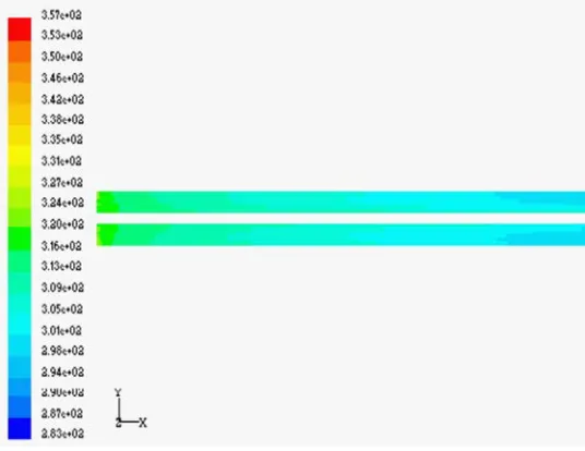
For the analysis purpose a shell and tube heat exchanger with pure axial flow on the shell side and non-uniformity on the tube side is considered.
First the usual case is considered in which all flow velocities are positive) there may arise a difference between the two mean temperatures i.e. average mass weighted temperature and average area weighted temperature, at the same cross-section of the heat exchanger. If the flow velocity is the same for all the channels, i.e. tube side plug flow, there is no difference between the two mean temperatures. If there is Non-Uniformity but the temperatures are the same for all the channels the two mean temperatures take the same value.
VII. CONCLUSION
As investigated in the two channel shell and tube arrangement heat exchanger without back flow, it is concluded that the average weighted temperature profile reduces to values lower than the mass weighted temperature profile. Even under the consideration of the flow to be uniform.
It is observed that the flow irregularities adversely affect the rate of heat transfer and mass flow rate through the flow passages. it is calculated that the temperature profile for non-uniformity without black flow falls below the temperature profile of uniform mass flow of fluid through heat exchanger.
VIII. FUTURE WORK
With finer grid generation accuracy can be increased to obtain optimized results through Computational analysis for different arrangement of tube channels and multiple pass flow pattern of heat exchangers.
Also the rate of heat transfer and total flow rate are important consideration in these systems. These quantities may be used for optimization. The resulting temperature of fluid being heated or cooled, the efficiency of the equipment, energy losses may also be chosen as objective functions for analysis of the system
IX. REFERENCES
[1]Sahoo, R. K., and Wilfried Roetzel, 2002. "Hyperbolic axial dispersion model for heat exchangers" International Journal of Heat and Mass Transfer 45,pp.1261-1270
[2]Yimin Xuan, and Wilfried Roetzel., “Stationary and dynamic simulation of multipass shell and tube heat exchangers with the dispersion model for both fluids” Int. J. Heat Mass Transfer. Vol. 36, No. 17,4221A231,
[3]Wilfried roetzel and Das, S.K., 1995 “Hyperbolic axial dispersion model: concept and its application to a plate heat exchanger” Int..J. Heat Mass Transfer. Vol. 38, No. 16, pp. 3062-3076.
[4]Roetzel, W., Spang, B., Luo, X., and Dash, S.K., 1998 “Propagation of the third sound wave in fluid : hypothesis and theoretical foundation” International Journal of Heat and Mass Transfer 41, pp. 2769.-2780.
[5]Anindya Roy, and Das, S. K., 2001," An analytical solution for a cyclic regenerator in the warm-up period in presence of an axially dispersive wave" Int. J. Therm. Sci. 40, pp.21-29
[6]TEMA, 1988 Standards of the Tubular Exchanger Manufacturers Association, New York 7th edition
[7]Haran, Ravindra Reddy, “Thermal Analysis of shell and tube heat exchanger using C and Ansys” –Volume 4 issue 7 July 2013
[8] S. B. Revagade, K. G. Deshmukh, S. V. Nemane and R. V. Marode. “Analysis of different type of tubes to optimize the efficiency of heat exchanger” International Journal of Innovative Science, Engineering & Technology, Vol-2 Issue 3, March 2015
AUTHORS
First Author – Kirti Onkar Prajapati, M. Tech Research Scholar, Dept. of Thermal Engg., PCST, Bhopal,
Second Author – Harshwardhan Uddhage, M. Tech Research Scholar, Dept. of Thermal Engg., PCST, Bhopal, [email protected]
Third Author – Sanjay Kumbhare, Assistant Professor, Dept. of Thermal Engg., PCST, Bhopal,
Fourth Author – Krishna Kumar Thakur, Associate Professor, Dept. of Thermal Engg., PCST, Bhopal, [email protected]
[image:5.612.38.306.56.263.2]Correspondance Author – Kirti Onkar Prajapati, M. Tech Research Scholar, Dept. of Thermal Engg., PCST, Bhopal, [email protected] , Contact No. 8827737757, 9595861257 Fig. 5 Temperature contours for Non-uniformity with