Design and Implementation of Solar Tracking System
through PIC Controller
Ei Phyu Soe*
Department of Electrical Systems and Instrumentation, Myanmar Aerospace Engineering University, Meiktila Township, Mandalay Division, Myanmar
DOI: 10.29322/IJSRP.9.08.2019.p9248 http://dx.doi.org/10.29322/IJSRP.9.08.2019.p9248
Abstract- Solar energy is considered to be as a renewable energy solution for most of energy crises and environmental pollutions. Sun always moves from east to west direction independent of weather condition. So with this concept, movement of the solar panel without using sensors is done with the help of programme loaded into the microcontroller. Solar tracking enables more energy to be generated because the solar panel is able to maintain a perpendicular profile to the sun’s rays .As such, it is vital that those in engineering fields understand the technologies associated with this area. This thesis describes the design and implementation of solar panel tracking system by using PIC microcontrollers. These solar tracking systems are controlled using PIC16F887 Microcontroller for vertical axis and PIC16F84A Microcontroller for horizontal axis. Two stepper motors (NEMA17) is mounted to control the vertical axis and horizontal axis. The project includes the design and construction of Solar Tracking Control with the associated electronic circuits. This prototype is designed for double axis to solve solstice problem. The PIC Microcontrollers are programmed using C language in microC PRO for PIC.
Index Terms- solar tracking system, PIC microcontroller, stepper motor, double axis, microC PRO.
I. INTRODUCTION
Now, many people use solar energy or photovoltaic energy as an alternative power because it is free and renewable. The sun is the central body of this planetary system; it is the star closest to the earth. Nowadays, solar energy has been widely used in the world, and it's expected to grow up in the next years. One of the most important problems facing the world today is the energy problem. This problem is resulted from the increase of demand for electrical energy and high cost of fuel. The solution was in finding another renewable energy sources such as solar energy, wind energy, potential energy etc.
Radiation from the sun can be converted into usable energy through thermodynamic processes. However, concentrating the energy from the sun can be difficult because the incident radiation that reaches Earth is spread out over a large area. Moreover; the solar panel that many of the users use is only in one way direction. If the sun located at the direction that is not perpendicular to the solar panel, the power that can be generate is low when comparing to the sun located exactly perpendicular to the solar panel. The sun rotates from east to west during a day, from north to south over a year but the highest power that can be generate by the solar panel when the solar panel is perpendicular to location of the sun.
Therefore, it is needed to rotate the solar panel in order to follow the sun’s direction. Tracking systems try to collect the largest amount of solar radiation and convert it into usable form of electrical energy (DC voltage) and store this energy into batteries for different types of applications. The sun tracking systems can collect more energy than a fixed panel system collects.
II. HARDWARE AND SOFTWARE USED IN SOLAR TRACKING SYSTEM
Solar Tracking System
The solar tracker that designed is a two axis tracker, which will track the sun on both horizontal and vertical axis. This is achieved by building a prototype that consisted of many individual parts. Some of the key hardware that used is
1) Stepper motors
2) PIC 16F microcontrollers 3) Driver circuit (L298N) 4) 7-segment display
In order to make the system completely, all these hardware had to be linked together.
1) Stepper Motor
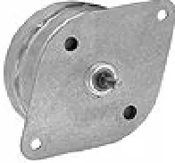
[image:1.612.410.508.532.623.2]Stepper motors are commonly used for precision positioning control applications. All stepper motors possess five common characteristics which make them ideal for this application. Namely, they are brushless, load independent; have open loop positioning capability, good holding torque, and excellent response characteristics.
Figure 1 Stepper motor
ISSN 2250-3153
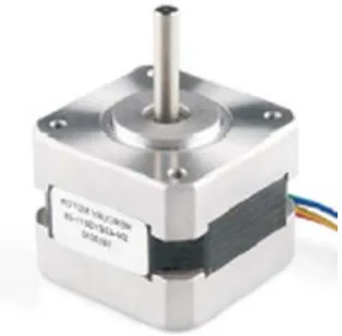
[image:2.612.91.248.89.243.2]provide greater positioning accuracy. This results in 0.9 degrees-per-step. NEMA 17 stepper motor is shown Figure 2
.
Figure 2 NEMA 17 stepper motor
2) PIC16F887 Microcontroller
PIC 16F887A is one of the most commonly used microcontrollers especially in automotive, industrial appliances and consumer applications .PIC16F887 is at the upper end of the mid-range series of the microcontrollers developed by microchip Inc. It can be reprogrammed and erased up to 10,000 times. Therefore it is very good for new product development phase. There are 40 pins on PIC 16F887. Most of them can be used as an I/O pin.
Figure 3 Pin Diagram
3) Motor Drive Circuit
The Motor Shield is based on the L298, which is a dual full-bridge driver designed to drive inductive loads such as relays, solenoids, DC and stepping motors. It can be drive two DC motors, controlling the speed and direction of each one independently. All inputs are TTL compatible. Each output is a complete totem-pole drive circuit with a Darlington transistor sink and a pseudo Darlington source. Two enable inputs are provided to enable or disable the device independently of the input signals. The driver has some features such as wide supply voltage range 4V to 35V, separate input logic supply, thermal shutdown, high noise immunity inputs, and output current 2A per
channel, peak output current 4A per channel and output clamp diodes for inductive transient suppression.
[image:2.612.336.551.163.264.2]L298N driver uses four input pins and two enable pins to configure the operation of a stepper motor. Digital output pin of PIC microcontroller are wired to four input pin of the driver to control the direction of the motor. Two enable pins are connected to the supply pin of the microcontrollers.
Figure 4 Motor Driver Circuit
4) 7-Segment Display
There are two types of 7-segment display: common anode (CA) and common cathode (CC). Basically the display consists of seven segments of LEDs connected either as common anode or common cathode. In a common anode display the anodes of all the LED segments are connected together and the signals are sent to the individual cathode segments as shown in Figure 5. Similarly, all the cathodes are connected together in a common cathode display and the signals are sent to the individual anode segments. Table 1. .shows the segments that should be turned on to generate the decimal numbers 0 to 9.
Figure 5 The signals are sent to the individual cathode segments
[image:2.612.46.284.393.549.2] [image:2.612.334.552.482.632.2]Table 1 The segments are turned on to generate the decimal numbers 0 to 9
Number
0
1 2 3
4 5
6 7 8
9
g f e d c b a
0 1 1 1 1 1 1 0 0 0 0 1 1 0
1 0 1 1 0 1 1 1 0 0 1 1 1 1
1 1 0 0 1 1 0 1 1 0 1 1 0 1
1 1 1 1 1 0 0
0 0 0 0 1 1 1 1 1 1 1 1 1 1
1 1 0 0 1 1 1
III. CONSTRUCTION OF TWO AXIS SOLAR TRACKING SYSTEM
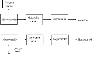
In order to make the automatic solar tracker, all the components are linked together to track the sun. It was very important to design the system carefully so that slightest movement of the sun can be tracked. The two complete circuits used to track the sun are Figure 7and Figure 8 one of microcontrollers is responsible for tracking the sun on each of the two axes. In the circuit, timer of PIC microcontroller is used and for seasonal changes push-button switch is also utilized in controller of horizontal axis for tiling solar panel by manually. Without using sensor, movement of solar panel is done with the timer of PIC.
When reaching specific time, microcontrollers control the movement of stepper motor. As each stepper motor have 4 electromagnets so 4 pulses are required from the microcontroller for each of the stepper motors. Since the stepper motors have high current rating so the pulse generated by the PIC 16F microcontrollers is not sufficient to drive the stepper motors.
So, to amplify the current output from the microcontroller L298N module driver is used. As the pulse are given in sequence from the microcontroller so the stepper motors receive the pulse accordingly telling them which way to move and how many steps to move.This mechanism allows the whole system to continuously track the sun throughout the whole day.
Motor drive
circuit Stepper motor Microcontroller
CW/CCW button
Horizontal axis Motor drive
circuit Stepper motor
Microcontroller Vertical axis
7-segment display
[image:3.612.57.264.70.253.2]
[image:3.612.357.572.305.471.2]
Figure 6 Hardware Block Diagram
Figure 7 Hardware Circuit Diagram of Vertical Axis
Figure 8 Hardware Circuit Diagram of Horizontal Axis
IV. TEST AND RESULT
A. Overall Circuit Diagrams of Solar Tracking System
[image:3.612.51.247.554.677.2]ISSN 2250-3153
[image:4.612.339.562.55.188.2]http://dx.doi.org/10.29322/IJSRP.9.08.2019.p9248 www.ijsrp.org
Figure 9 Simulation circuit diagram of solar tracking system for vertical axis
[image:4.612.40.275.56.163.2]For giving pulses PORTB pins of PIC 16F84A are connected to input pins of L298N motor driver and are also connected LEDs. When running the motor, LEDS also emit light. If a push-button switch connected RA2 is pressed, the motor changes in the direction.
Figure 10 Simulation circuit diagram of solar trackung system for horizontal axis
B. Controller Circuits
The sample arrangement of controller circuit on project board is shown in figure. Four 7-segmens display minutes and seconds. The right two display seconds and others are for minutes. When it reaches at 10minutes, PIC output pins will transmit output signals.
[image:4.612.358.576.288.406.2]Figure 11 Testing controller circuit (PIC16F887)
Figure 12 Testing controller circuit (PIC16F887)
The following figure is controlling circuit of PIC16F84A for horizontal axis .In this circuit, switch is utilized to control the clockwise / counterclockwise direction of the motor. Three LEDS also include to display condition (CW /CCW).
Figure 13 Testing controller circuit in project board (PIC16F84A)
[image:4.612.37.272.295.426.2] [image:4.612.351.582.457.583.2] [image:4.612.47.274.582.718.2]http://dx.doi.org/10.29322/IJSRP.9.08.2019.p9248 www.ijsrp.org Table 2 Data of Solar Panel during Hardware Testing
Table 2 shows the data of voltage, current and power received from solar tracking system and static solar panel for a day.
V. CONCLUSION
This paper has presented a means of tracking the sun’s position with the help of microcontroller. Specially, it demonstrates a working software solution for maximizing solar cell output by positioning a solar panel at the point of maximum light intensity. Built in timer of PIC is used in this system so that it responses more accurately. Even in a cloudy day when intensity of sun light may vary at different time of a day, the timer can be more that handy to drive solar panel correctly in that low light. So the prototype represents a method for tracking the sun both in normal and weather condition. Moreover, the tracker can initialize the starting position itself which reduce the need of any more photo resistors. To solve summer solstice and winter solstice the solar panel is titled manually with the help of switch. The PIC microcontrollers are programmed using C language in microC PRO PIC. So C language has been studied in detail. In addition; the design of mechanical structure and electrical circuit has been understood.
REFERENCES
[1] Ms Ei Thwe Win, Design and Implementation of Solar Tracking Control System Using Microcontroller, 2012.
[2] Romy Kansal, PIC Based Automatic Solar Radiation Tracker, 2008. [3] JAD ABOU ASSALY, Dual Axis Solar Tracker, 2012.
[4] Bill Lane, Solar Tracker, 2008
[5] A.K. Saxena and V. Dutta, A Versatile Microprocessor Based Controller for Solar tracking, Phothvoltic Specificalist Conference, vol.2 pp.1105-1109, 1990.
[6] Stepper Motor Basics, www. Solarbotics.net/library/ pdflib/pdf/motorbas.pdf.
[7] B.Koyunch and K. Balasubramanian, A Microprocessor Controlled Automatic Sun Tracker, IEEE transactions on Counsumer Electronics, vol.37, no.4, pp.913-917,1991
[8] Mohamard Fazman Bin Mohamad Yunus, Design and Development of a Solar Tracking System, 2010.
[9] Md. Tamvir Arafat Khan, S.M.Sharhrear Tanzil, Rifat Rahman, S M Shafiual Alam, Design and Construction of an Automatic Solar Tracking System, international conference on electrical and computer engineering, Dhaka, Bangladesh, 2010.
AUTHORS