APPLICATION OF ADDITIVE MANUFACTURING / 3D PRINTING
TECHNOLOGIES AND INVESTMENT CASTING FOR PROTOTYPE
DEVELOPMENT OF POLYCRYSTALLINE DIAMOND COMPACT (PDC)
DRILL BIT BODY
Khurram Altaf1, Ahmad Majdi Abdul Rani1, Dereje E. Woldemichael1, Tamiru A. Lemma1, Chou Zhi Jian1 and Muhd Helmie Fiqri2
1Department of Mechanical Engineering, Universiti Teknologi Petronas, Malaysia
2Department of Petroleum Engineering, Universiti Teknologi Petronas, Bandar Seri Iskandar, Perak, Malaysia E-Mail: [email protected]
ABSTRACT
This study is about the application of Additive Manufacturing (AM) technologies for the manufacturing of an improved design of Polycrystalline Diamond Compact drill bit body by using Thermojet three dimensional printing and investment casting. The aim of study is to investigate a faster and effective PDC drill bit manufacturing process without compromising the mechanical aspects of the fabricated model. The conventional fabrication processes could be lengthy and cost intensive for the development of a complex product. With the rapidly developing technologies, the aspiration of manufacturing rate is keep rising and will be higher in future for sure. To overcome these issues, AM is one of the tool between the manufacturing rate and high precision product. In the current study, a computer aided design (CAD) of PDC bit body model that was modified from a previous design was taken and sectioned into parts to optimize the three dimensional printing process. Wax patterns were created using AM in separate sections for minimizing the support structure. Then the drill bit body was casted using investment casting process. The end result was a PDC drill bit body fabricated with steel material.
Keywords:PDC drill bit body, additive manufacturing, 3d printing, investment casting.
INTRODUCTION
Additive manufacturing technologies are also known as Rapid Prototyping (RP), or commonly referred to as “3D printing (3DP)”. The manufacturing technology is different with traditional manufacturing method due to the technique of additive process. It is a manufacturing technique of producing a product with a manner of layer by layer deposition of material without any subtraction of bulk material. For the earlier stage, it has been invented to improve the industry performances. Since the technology have multiple advantages especially environmental friendly, it gave attention to the researchers to invest the technology and invented the following additive manufacturing machines such as Laser Sintering, Fused Deposition Modelling (FDM) and Binder Jetting. This manufacturing technology has covered many fields in our daily life such as prototyping, biotechnology, fashion, architecture and automotive.
Advantages
The development of the AM technology has been forwarded into next era with a wide range of materials used by the machines, higher accuracy and reducing the relative cost of production. AM is a fabrication method with high potential to improve the conventional manufacturing methods in the future due to its characteristics such as no need for tooling in a mass customization, short production time, relatively economical for mass production with complex configuration and able to minimize the material waste produced [1]. The advance of technology is impressing
some designers and artists too since it is able to build up their desired ideas precisely with high levels of complexity. Furthermore, final product can be done without a large number of skilled craftsmen and longer periods of time [2].
Availability of materials
In the early stages of technology development, 3D printing is mainly focus on polymeric materials. Within some period of development, the technology start to involve metals, ceramic and composites as its printing materials. Those materials can be printed with one kind or a combination. A combination material powders (composite) have an advantage compared to single material chosen [3]. For rapid tooling, metal material powders are formed as a compound of two or more for the operation especially in sand casting [4]. However, the rapid development have moved the technology facing the edge or shortage of material to produce some special product with only metal powders, ceramic and polymers.
Support material
STereoLithography (STL) files. Some processes like Selective Laser Sintering (SLS) and powder based 3D printing does not need supports as the powder itself supports the overhanging structures of the part. A typical support structure with the build part is shown in Figure-1 with red color indicating the support structure.
Figure-1. (a) A part with a protruding section which requires support material. (b) Common support structures
used in rapid-prototyping machines. [6]
Material jetting (Thermojet printer)
Materials used in this 3D printing process are in their molten state or liquid form and ejected out from a different nozzles located on a print head. This process has multiple nozzle from which the molten material flows. After analyzing the format data, the nozzles will start to operate according to the build format. The material jetting out from the nozzles will form the model and the support material for the overhanging geometries and empty space inside the part. The nozzles will resume when the first layer is partially solidified. Thus, the process of the material jetting is also known as solidification of molten material [7].
Even though, there are a lots of RP technologies available these days, the general procedures are almost similar for all of them (Figure-2) which are designing, converting to STL files, pre-process, RP fabrication, and post process.
Figure-2. Typical RP process chain [8]
Traditional manufacturing of PDC drill bit body Polycrystalline Diamond Compact (PDC) Drill bit acts as one of the major role in the oil and gas discovery. It was named after PDC due to first development of drill bit that used synthetic diamonds as cutting elements back in 1973 [9]. It is used in drilling operation to drill a well aiming to find and developing new petroleum reserves. The successfulness of the operation depends mainly on the drill bit’s performance. Due to the importance of it, a lot of researches and developments have been done on this particular equipment to further understanding of cutter/formation connection, cutter performance, bit dynamics and bottom hole assembly
dynamics. It all started in the late 1980s, where the first modelling studies conducted by Sandia Laboratories that the analysis between the cutting elements of a PDC drill bit and the formation drilling has been widely investigated [9].
Conventional manufacturing method of PDC drill bit body currently are working in the subtractive manners, where the built material is removed from the main part until it achieves the final form of the PDC drill bit body. This process is applied to the smaller and less complex structure of PDC drill bit body. For the larger and more complex structure, the initial production of mold is required in order to get the final form of the PDC drill bit body. Both of these methods undergo the same subtractive manners which contributes to the problem of having a large number of waste materials. Other than that, it is undeniable that most of the manufacturers use an advanced technology of machines to help shaping the PDC drill bit body until it reach the final accuracy model. In doing so, a lot of machines with different size of cutting elements is needed and number of process will also increases. Production period for a complex structure like the PDC drill bit body is counted by weeks. It is consider not economic if there is too much time loss in production, purchasing expensive tooling, and multiple works required to produce a scale model with the conventional manufacturing methods.
The basic sequence to produce a steel bit pattern is machining multiple bulk metal into a desired form by using computer numerical control (CNC) machine. The pattern can be two or multiple pieces of moulds or dies for further process a reproducible complex pattern body. Complex multiple patterns has its advantage without intermediate, which is reusable for next production. The variation of the patterns are able to replace by another modified parts after correction is done. Then, this combination of patterns in a desired form will proceed to pouring of molten steel. Break the shell mould from casting at the end of the cooling period, and proceed to substantial reduction in machining for the final bit formed. Amongst the steps, process of casting is about few percent of time consumed and a low investment over the entire fabrication only. Most of the time and investment were used for the pattern preparation since it included those expensive tooling machine and high load of material used [10].
The main objective for the current study is to fabricate a PDC drill body using Additive Manufacturing technology with the support of investment casting technique.
METHODOLOGY
CAD model modification
increased and changed in shape accordingly to actual drill bit flow line in Figure-3(b). A groove joint was inserted on the top side and bottom side model to ease merge after investment casting.
Figure-3(a). Original CAD models of PDC drill bit body, top and bottom sections.
Figure-3(b). Modified CAD models of PDC drill bit body
It is necessary to section or slice open the CAD model for the top section to expose all the hollow section and inner surface of the PDC drill bit body to minimize the support material. Moreover, the original oversized model was difficult to 3D print as a single unit due to the machine printing limits. After some considerations, the model has divided into three parts and saved in different STL file format. Then, they were 3D printed out as Figure-4 below.
Figure-4. Division of model and 3D printing orientation
Post-processing
Post processing in the Thermojet 3D printing process is referred as the removing of the support structure. The PDC drill bit body wax pattern was divided into three parts and 3D printed individually. The process of removing support material was started from outer surface then inner surface by using hand tools. Those surfaces have to be cleaned out before undergo casting to ensure the closer dimension tolerances. Figure-5 shows the completed part with support structure and Figure-6 shows the part being separated from the build plate and removing the support structure in the post processing stage.
Figure-5. Part with support structure
Figure-6. Part separation from build plate and support material removal in post processing
Investment casting
Investment casting (IC) or “lost-wax” casting, is a precision casting process whereby wax patterns are converted into solid parts following a multi-step processes. IC enables economically-production of dimensionally accurate components and is proven to be better in every aspect such as cost and time, as the process itself minimized the waste material and can be done in a short period of time. Besides, IC allows the production of intricate geometries and features from variety type of metals with a high precision and accuracy [8].
304 as suggested by the foundry. The properties of different steel alloys are given in Table-1.
Table-1. Standard specification of steel alloys [11].
The properties of TJ2000 are shown in Table-2 below.
Table-2. Thermojet material properties.
RESULT AND DISCUSSION
For the investment casting process, TJ2000 material was chosen due to its properties such as melt temperature, softening temperature, volume of shrinkage and ash content produced. It is a good material for investment casting since it only leaves 0.01% of ash following being burnt in 500oC during de-waxing process. The sacrificial wax pattern for PDC bit body in separate sections and in assembled form are shown in Figure-7(a) and (b).
Figure-7(a). Wax patterns for the top and bottom sections.
Figure-7(b). Assembled pattern.
The analysis of sacrificial wax pattern printed with Thermojet 3D printer and investment casted stainless steel prototype revealed some issues to discuss further for the next stages of study. The removal of support structure from the difficult to access features of the wax pattern was one of the issues. To overcome this particular issue, the pattern was sectioned into 3 parts to have access to the support structure for easy removal.
Results for the investment casted drill bit body
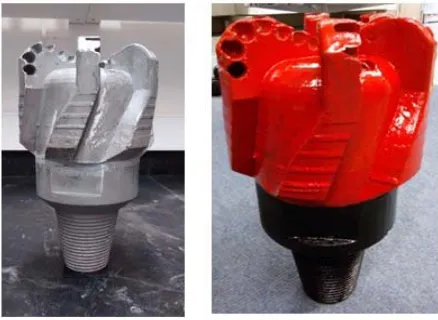
the sacrificial wax pattern. It can be crack out to become a perfect drill bit cutter hole after investment casting. This method not only can provide a fit hole for cutter installation after but also reduce the risk of porosity. The final casted bit body is shown in Figure-8, before and after painting.
Figure 8. Investment casted PDC bit body
CONCLUSIONS AND RECOMENDATIONS
The current study has provided an analysis of Additive Manufacturing techniques and its application to manufacture a metal prototype of a PDC bit body. Some important conclusions and recommendations can be drawn as follows:
Application of Additive Manufacturing and investment casting in the fabrication of PDC drill bit body could be a faster and effective technique. More study is required in this respect.
Proper sectioning process for complex model is required to ensure the usability for investment casting. For a part with closed or difficult to reach features, its pattern should be sectioned in order for the part to be assessable for removing the support structure for a better pattern quality to be used in investment casting.
Small holes and cavities of the wax pattern filled with ceramic-based material or tungsten carbine to provide a good stability of holes for investment casting. It is recommended that the next study on this topic should be focused on the combination of upper and bottom section of PDC drill bit body as a single part to be used in the investment casting process. Other types of AM technologies can also be considered to be used for fabrication like Direct Metal Laser Sintering (DMLS) and Selective Laser Melting (SLM).
ACKNOWLEDGEMENTS
The authors would like to thank Universiti Teknologi PETRONAS for providing 3D printing laboratory facilities and financial assistance through
Yayasan Universiti Teknologi Petronas (YUTP) to facilitate this research.
REFERENCES
[1] Khajavi, S. H., Partanen, J., & Holmstrom, J. (2014), “Additive manufacturing in the spare parts supply chain”, Computers in Industry, 65, 50 - 63.
[2] Hudson, S. E. (2014), “Printing Teddy Bears, A Technique for 3D Printing of Soft Interactive Objects”, Human-Computer Interaction Institute, Carnegie Mellon University and Disney Research Pittsburgh.
[3] Kumar, S., & Kruth, J. P. (2009), “Composites by rapid prototyping technology”, Materials and Design, 31, 850 - 856.
[4] Gausemeier, I. J. (2011), “Analysis of Promising Industries thinking ahead the future of Additive Manufacturing”, Direct Manufacturing Research Center, Heinz Nixdorf Institute, University of Paderborn.
[5] Gardan, N., & Schneider, A., (2014), “Topological optimization of internal patterns and support in additive manufacturing”, Journal of Manufacturing Systems, JMSY-315.
[6] Jacobs, P. F., (1992) Rapid Prototyping & Manufacturing: Fundamentals of Stereolithography. Society of Manufacturing Engineers.
[7] Pham, D. T., & Gault, R. S. (1998), “A comparison of rapid prototyping technologies”, International Journal of Machine Tools & Manufacture, 38, 1257 - 1287.
[8] Cheah, C. M., Chua, C. K., Lee, C.W., Feng, C, Totong, K., (2005) "Rapid prototyping and tooling techniques: a review of applications for rapid investment casting”, International Journal of Advanced Manufacturing Technology 25(3-4): 308-320.
[9] Kerr, C. J. (1988), "PDC drill bit design and field application evolution." Journal of petroleum technology 40(03): 327-332.
[10]Symonds, D. H., “Production Process for casting steel-bodied bits” US Patent No. 5,893,204, Nov 12, 1996.