A Real Time Two Hand Gesture Recognition System
Using Motion Static and Dynamic Image in British Sign
Language
Pingale Prerna Rambhau *, Prof.Rokade S.M ** *
Department of Computer Engineering,Sir Vishaveshwaray Institute Technology, Chincholi, Tal-Sinner,Dist- Nashik ,India **
Head, Computer Engineering Department,Sir Vishaveshwaray Institute Technology, Chincholi, Tal-Sinner,Dist- Nashik ,India
Abstract- The introduce of finger spelling two hand gesture with the real time stereo vision hand tracking for implementation and analysis, used for interaction purpose. Many researchers have proposed methods that hand posture estimation. We have propose on two hand gesture recognition system using real time video image, the hand of fingers is extracting using contour with its features like finger shape with static and dynamic image, motion hand etc. The input of the system as BSL finger spelling which is recognition by using contour analysis and extraction. The experimental performance of system is tested in real time hand tracking world, which present results around 60% recognition rate efficiency.
Index Terms- Finger Spelling, hand posture estimation, static and dynamic image.
I. INTRODUCTION
he system can track the 2D position and 3D position index finger gestures of two hands without the use of gloves or any type special markers. In world, some people is ‘deaf with handicapped’, like someone who is blind, they cannot ride a bike, can’t drive a car, do not go to work, shop, and can’t go on vacation like everybody else. The major problem for deaf and dumb peoples is “Communication”. The objective to help the deaf and dump people or non vocal persons to improve the skills on communication between non vocal person and normal person and bring them in flow of society [2].
The system has four parts which is: 1) hand segmentation: from image sequences to segment the region of the hand , 2) key hand posture selection: From image sequence to determine the key frame which representing the hand posture of Finger-spelling symbols, 3) hand feature definition: to define the finger shapes symbol and hand features as contour extraction sequence, 4) finger-spelling recognition, to recognize the finger-spelling from hand features from real time image sequences[1].
II. RELATED WORK
A. Literature Survey
To summarize, the previous works on finger-spelling recognition, In [1] Kittasil Silanon, Nikom Suvonvorn, its features, such as, finger shape, and hand appearance, had been defined as chain code, which are input to the American finger-spelling recognition system by using a vote method. The
performance of the system is tested in real-time environment, which results in around 70% recognition rate. In [3] K. Otiniano Rodrguez, G. Camara-Chavez, design to hybrid system approach for finger spelling recognition using RGB-D information from KinectTM sensor and its approach has anaccuracy rate of 91.26% when RGB and depth information is used, outperforming other state-of-the-art methods. In [4] Md. Atiqur Rahman, presents a system for recognizing static hand gestures of alphabet in Bangla Sign Language (BSL). A BSL finger spelling and an alphabet gesture recognition system was designed with Artificial Neural Network (ANN) and constructed in order to translate the BSL alphabet into the corresponding printed Bangla letters. In [5] Nicolas Pugeault and Richard Bowden, presents an interactive hand shape recognition user interface for American Sign Language (ASL) finger-spelling.In [6] Dominique Uebersax, Juergen Gall, Michael Van den Bergh, Luc Van Gool, BIWI, ETH Zurich 2ESAT-PSI / IBBT, KU Leuven, present a system for recognizing letters and finger-spelled words of the American sign language (ASL) in real-time. See in [7] [8], report results on a dataset of 1,000 low quality webcam videos of 100 words. The proposed method achieves a word recognition accuracy of 98.9%. In [9] Paul Goh, presents the Auslan Finger-spelling Recognizer (AFR) that is a real-time system capable of recognizing signs that consists of Auslan manual alphabet letters from video sequences.
B. Implementation Details
1. Overview of Emgu CV: Emgu CV is a cross platform .Net wrapper to the OpenCV image processing library. Allowing OpenCV functions to be called from .NET compatible languages such as C#, VB, VC++, IronPython etc. The wrapper can be compiled in Mono and run on Windows, Linux, Mac OS X, iPhone, iPad and Android devices.
2.Overview of Emgu CV Versions:
3.Advantage of Emgu CV
• Cross Platform
• Image class with Generic Color and Depth • Automatic garbage collection
• XML Serializable Image
• XML Documentation and intellisense support • The choice to either use the Image class or
direct invoke functions from OpenCV
4.Architecture Overview
Fig.2. Architecture of EmguCV
Emgu CV has two layers of wrapper as shown above Fig.2 • The basic layer (layer 1) contains function, structure and enumeration mappings which directly reflect those in
OpenCV.
• The second layer (layer 2) contains classes that mix in advantanges from the .NET world.
5.Wrapping OpenCV
I. Function Mapping - Emgu.CV.CvInvoke: The CvInvoke class provides a way to directly invoke OpenCV function within .NET languages. Each method in this class corresponds to a function in OpenCV of the same name. For example, a call to:
IntPtr image = CvInvoke.cvCreateImage(new
System.Drawing.Size(400, 300),
CvEnum.IPL_DEPTH.IPL_DEPTH_8U, 1);
is equivalent to the following function call in C
IplImage*image=cvCreateImage(cvSize(400,300), IPL_DEPTH_8U, 1);
Both of which create a 400x300 of 8-bit unsigned grayscale image.
II.Structure Mapping - Emgu.CV.Structure.Mxxx: This type of structure is a direct mapping to OpenCV structures.
III. Enumeration Mapping - Emgu.CV.CvEnum: The CvEnum namespace provides direct mapping to OpenCV enumerations. For example,
CvEnum.IPL_DEPTH.IPL_DEPTH_8U has the same value as IPL_DEPTH_8U in OpenCV; both of which equals 8.
6.Depth and Color as Generic Parameter:
An Image is defined by its generic parameters: color and
depth. To create a 8bit unsigned Grayscale image, inEmgu CV
it is done by calling
Image<Gray, Byte> image = new Image<Gray, Byte>( width, height);
Not only this syntax make you aware the color and the depth of the image, it also restrict the way you use functions and capture errors in compile time. For example, the SetValue(TColor color, Image<Gray,Byte> mask) function in Image<TColor, TDepth> class (version >= 1.2.2.0) will only accept colors of the same type, and mask has to be an 8-bit unsigned grayscale image. Any attempts to use a 16-bit floating point or non-grayscale image as a mask will results a compile time error!
7. Creating Image:
Although it is possible to create image by calling CvInvoke.cvCreateImage, it is suggested to construct a
Image<TColor, TDepth> object instead. There are several advantages using the managed Image<TColor,TDepth> class.
• Memory is automatically released by the garbage collector
• Image<TColor, TDepth> class can be examined by Debugger Visualizer
• Image<TColor, TDepth> class contains advanced method that is not available on OpenCV, for example, generic operation on image pixels, conversion to Bitmap etc.
I.Image Color:
The first generic parameter of the Image class specific the color of the image type. For example
Image<Gray, ...> img1;
indicates that img1 is a single channel grayscale image.
Color Types supported include:
• Gray
• Bgr (Blue Green Red) • Bgra (Blue Green Red Alpha) • Hsv (Hue Saturation Value) • Hls (Hue Lightness Saturation) • Lab (CIE L*a*b*)
• Luv (CIE L*u*v*)
II. Image Depth:
Image Depth is specified using the second generic parameter Depth. The types of depth supported in Emgu CV
1.4.0.0 include • Byte • SByte • Single (float) • Double • UInt16 • Int16 • Int32 (int)
a. Creating a new image:
To create an 480x320 image of Bgr color and 8-bit unsigned depth. The code in C# would be
Image<Bgr, Byte> img1 = new Image<Bgr, Byte>(480, 320);
If you wants to specify the background value of the image, let's say in Blue. The code in C# would be
Image<Bgr, Byte> img1 = new Image<Bgr, Byte>(480, 320, new Bgr(255, 0, 0));
b. Reading image from file:
Creating image from file is also simple. If the image file is "MyImage.jpg", in C# it is
Image<Bgr, Byte> img1 = new Image<Bgr, Byte>("MyImage.jpg");
c. Creating image from Bitmap
It is also possible to create an Image<TColor, TDepth> from a .Net Bitmap object. The code in C# would be
Image<Bgr, Byte> img = new Image<Bgr, Byte>(bmp); //where bmp is a Bitmap
8. Methods:
Naming Convention
• Method XYZ in Image<TColor, TDepth> class corresponds to the OpenCV function cvXYZ. For example,
Image<TColor, TDepth>.Not()
function corresponds to cvNot function with the resulting image being returned.
• Method _XYZ is usually the same as Method XYZ except that the operation is performed inplace rather than returning a value. For example,
Image<TColor, TDepth>._Not()
function performs the bit-wise inversion inplace.
9.Drawing Objects on Image:
The Draw( ) method in Image< Color, Depth> can be used to draw different types of objects, including fonts, lines, circles, rectangles, boxes, ellipses as well as contours. Use the documentation and intellisense as a guideline to discover the many functionality of the Draw function.
10. Color and Depth Conversion:
Converting an Image<TColor, TDepth> between different colors and depths are simple. For example, if you have Image<Bgr, Byte> img1 and you wants to convert it to a
grayscale image of Single, all you need to do is Image<Gray, Single> img2 = img1.Convert<Gray, Single>();
11.Displaying Image: Using ImageBox:
Emgu CV recommends the use of ImageBox control for display purpose, for the following reasons:
• ImageBox is a high performance control for displaying image. Whenever possible, it displays a Bitmap that shares memory with the Image object, therefore no memory copy is needed (very fast).
• The user will be able to examine the image pixel values, video frame rates, color types when the image is being displayed.
• It is convenient to perform simple image operations with just a few mouse clicks.
III. MATHEMATICAL MODEL
Problem Definition:
The real time input image is processed in order to identify pixels that depict human hands.
Let A be a user ;such that A={U,S,H,M,L,C,T|Φa} where U represent the set of all pixels of an image; U={u1,u2,…..un}; M be the subset of U Corresponding to foreground pixels where to identify a human body such that M={m1,m2,…mn};
[image:3.612.373.526.446.537.2]and S be the subset of U containing pixels that are skin colored. And H stand for the sets of pixels that depict human hands. The relations between the above mentioned sets are illustrated in the Venn diagram shown in Fig. 6. The implicit assumption in the above formulation is that H is a subset of M, i.e. hands always belong to the foreground.
Fig. 3 Venn diagram representing the relationship between the pixel sets U, M, S and H.
Activity1
Let fs be a rule of S and H into U such as H be binary random variables (i.e taking values in 0,1), indicating whether a pixel belongs to S and H, such as:
(s1,s2,….,sn)|->{h1,h2,…,hn}ϵU
Activity2
let M be a binary variable (determined by the employed foreground subtraction algorithm) that indicates whether a pixel belongs to M such as:
(s1,s2,….,sn)ϵM
Let L be the 2D location vector containing the pixel image coordinates and let T be a variable that encodes a set of features regarding the currently tracked hypotheses such as
(l1,l2,….,ln)|->{t1,t2,…,tn}ϵU
Activity4
Given all the above, the goal of processing is to compute whether a pixel belongs to a hand, given
(a) the color c of a single pixel,
(b) the information m on whether this pixel belongs to the background (i.e. M = m) and, (c) the values l and t of L and T, respectively. Specify , the conditional probability:
P(h) = P(H=1;C=c; T=t; L=l M=m)
To perform this estimation to finding conture compression nodes{ S0,S1,S2,S3,S4.S5} in the correspond to random variables that represent degrees of belief on particular aspects of the problem. The edges in the graph are parameterized by conditional probability distributions that represent causal dependencies between the involved variables.
Efficiency factor:
S0: Foreground pixel(M) S1: Pixel Location (L) S2: Skin colored Object (S) S3: Hand Pixel (H)
[image:4.612.316.573.64.162.2]S4: Perceived Color(C) S5: Top-Down Information (T)
Fig. 4 Proposed Factors relationship
State Diagram:
Fig. 5. State diagram for whole system
S0: Start System
S1: Enter in Phase I( Sign to text conversion) S2: Enter in Phase II(Text to sign conversion) S3: Output of Phase I
S4: Output of Phase II
Fig. 6. State diagram for phase I system
q0: Start System
q1: Web Initialization (Web camera using USB) q2: Web Initialization (laptop camera )
q3: Capture image q4: Skin color extraction q5: Hand segmentation
q6: Mapping of image to corresponding alphabets q7: Construct sentence
q8: Show output text q9: speech conversion
Fig. 7. State diagram for phase II system
q0: Start system
q1: Provide sentence to the computer q2: word, alphabet separation
q3: Mapping of Character to each image q4: Show the images on system
IV. RESULT ANALYSIS
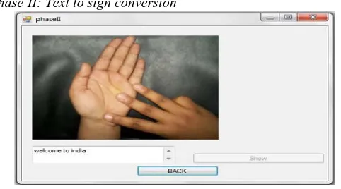
Phase II: Text to sign conversion
Fig. 8 Phase II:Text to sign conversion
In this sentences are scanned entered by user and then alphabets separation module separate the alphabets from sentences and corresponding image is display to viewers.
[image:4.612.321.562.503.637.2]Sign processing phase is the result of methods describe above that frame grabber, hull drawing, contour extraction and sign mapping. In output screen it display two sections first section displays input from user and second section displays binary images of capture image. At the bellow side It displays the text generated and button for speech conversion. In order to verify the efficiency of the proposed gesture recognition algorithm, an Intel Core with an USB camera is used in this experiment, and the program is coding under OpenCV.
Fig. 9 Phase I: sign to text conversion
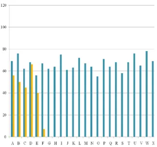
V. EXPERIMENTAL RESULTS
[image:5.612.61.274.171.277.2]In this section we represent the recognition results on Real Time Two Hand Gesture Recognition System Using Motion Static and Dynamic Image in British Sign Language.
Fig.10 Experimental Results
[image:5.612.44.206.366.518.2]Fig.11 Database of 0 to 9 numbers and Preprocessing results
Fig.12 Database of 26 sign alphabets and Preprocessing results
VI. CONCLUSION
In this paper, present a simple model of static and dynamic gestures of British Sign Language alphabet recognition system, does not require any special markers or The motivation for this hand tracker was a desktop-based two-handed interaction system in which a user can select and manipulate geometric in real time using natural hand motions. And finally with the help of this software communication barrier and dumb people and normal people get reduced.
ACKNOWLEDGMENT
We would like to express our sincere thanks and deep sense of gratitude to personnel who helped us during collection of data and give us their rare and valuable guidance for the preparation presentation of the report. We express our grateful acknowledgement to Prof.S.M.Rokade for giving us kind guidance inspiration to complete this report. We extend our sincere thanks to the Prof.S.M.Rokade Head of Computer Engineering Department. We also express our gratitude to our parents for their encouragement While concluding this acknowledgement we also express our sincere thanks to our friends, well wishers, our colleagues, staff members of SVIT,chincholi who extended their kind cooperation to complete this report.
REFERENCES
[1] Kittasil Silanon,Nikom Suvonvorn,”Finger- Spelling Recognition System using Fuzzy Finger Shape and Hand Appearance Features”,ISBN: 978-1-4799-3724-0/14/$31.00 2014 IEEE.
[2] Pingale Prerna Rambhau.”Recognition of Two Hand Gestures of word in British Sign Language (BSL)”.International Journal of Scientific and Research Publications,Volume 3, Issue 10, October 2013 ISSN 2250-3153. [3] Stephan Liwicki, Mark Everingham, Automatic Recognition of Finger
spelled Words in BritishSign Language, in Proc. IEEE Computer Society Conference on Computer Vision and Pattern Recognition Workshops, pp. 50-57, Miami, FL, USA, June, 2009.
[4] R. Feris, M. Turk, R. Raskar, K. Tan, and G. Ohashi. Exploiting depth discontinuities for vision-based fingerspelling recognition. In In IEEE Workshop on Real-time Vision for Human-Computer Interaction, 2004. [5] X.D. Huang, Y. Ariki, and M. A. Jack. Hidden Markov Models for Speech
Recognition. Edinburgh University Press, 1990.
[image:5.612.46.291.556.663.2][7] M. Jones and J. Rehg. Statistical color models with application to skin detection. IJCV, 46(1):8196, 2002.
[8] J. Schlenzig, E. Hunter, and R. Jain. Recursive identification of gesture inputs using hidden Markov models. Proc. Second Annual Conference on Applications of Computer Vision, pages 187 194, December 1994. [9] D. B. Nguyen, S. Enokida, and E. Toshiaki, Real-Time Hand Tracking and
Gesture Recognition System, IGVIP05 Conference, CICC, pp. 362-368, 2005.
AUTHORS
First Author – Pingale Prerna Rambhau, ME Second Year
Student,Department of Computer Engineering( University of
Pune), Sir Vishaveshwaray Institute Technology, Chincholi, Tal-Sinner,Dist- Nashik ,India, Email Id:
Second Author- Prof.Rokade S.M. Head,Computer Engineering