Effect of Optical Filtering for Error-free Transmission in
Optical Networks
M.Venkata Sudhakar
Research scholar Department of ECE JNT University, Kakinada
India
Y.Mallikarjuna Reddy
Professor Department of ECE
VVIT, Guntur India
B.Prabhakara Rao
Professor Department of ECE JNT University, Kakinada
India
ABSTRACT
This paper presents a new approach to maximize the dispersion-limited distance of vertical cavity surface emitting lasers (VCSELs) operating at 1550.127 nm with 10 Gb/s bit rate. Optical non return to zero (NRZ) signal is generated by using an optical band pass filter (OBPF) along with Mach-Zehnder interferometer (MZI) at the output of VCSEL. A third order super-Gaussian and fourth order Butterworth filters are used as optical filters. The dependence of bit error rate (BER), the eye opening and transmission distance on variations in the optical filter and MZI parameters is investigated. The numerical results signify that with the proposed scheme one can enhance the single mode fiber (SMF) link-length to 127 km in the absence of electrical or optical dispersion compensation methods. Results are compared between the proposed method and transmitters implemented with VCSEL diode.
General Terms
Optical communications.
Keywords
Single mode fiber, optical band pass filter, bit rate, dispersion
1.
INTRODUCTION
The increasing demand of high speed long-reach optical communication (OC) networks forces the implementation of high bit-rate and dispersion tolerant optical transmitters. Single mode fiber (SMF) is suitable for exchange of data, voice and video information in extended distance telephone networks. Vertical cavity surface emitting lasers (VCSELs) are typically intended for 10 Gb/s OC systems because of their cost-effectiveness and size.
VCSELs have been proposed as optical-source in many different applications like free space optical link [1], optical imaging [2], sensing [3,4], high data rate short links [5], Ethernet [6], mouse and printers [7], radio over fiber [8], spectroscopy [9, 10], optical backplanes [11, 12] , data centers [12], local area networks (LANs) and metro-area networks (MANs) [13].
The dispersion-uncompensated reach of electro-absorption (EA) and Mach-Zehnder (MZ) modulator based transmitters is restricted to 80 km of standard SMF for 10 Gb/s optical signals [14-16]. To minimize the price of access network, directly modulated VCSELs (DM-VCSELs) are known to be cost-efficient method in comparison with the transmitters with EA and MZ modulators for the reason that the external modulators are costly in addition to have higher size and larger power consumption.
VCSELs are usually cost-effective optical source offering larger bandwidth, completely tunable in C and L bands. The VCSEL presents a great number of merits such as greater coupling efficiency [17], single-mode operation [18], high speed and lesser threshold [19], reliability [20], enhanced quantum efficiency and optical power [21].The improvements of VCSEL compared to distributed bragg reflector (DBR) and distributed feedback (DFB) laser are little power consumption and low price because of its compactness [22].
At 10 Gb/s the existing reach of 1550 nm DM-VCSELs is approximately 10 km [23, 24] that is certainly inadequate to fulfill the access-network requirements, which is driving investigation in improving the reach and performance of SMF link using least cost approaches.
There exist several different methods to lessen the dispersion effects in SMF for VCSEL based system. One of the techniques for the size and cost alleviation is the removal of inverse dispersion fiber (IDF) [25] and dispersion compensating modules (DCMs) [26]. Electronic-dispersion compensation (EDC) [27] and injection locking [28] schemes are previously used as dispersion compensators to enhance the reach of a 10 Gb/s VCSEL, all these methods enhance the complexity and power consumption of the optical fiber system.
The adopted method presents an effective way to extend the dispersion-limited distance of VCSEL without reducing bit error rate (BER) and sensitivity of received signal. DM-VCSEL with simple filtering scheme is an attractive technique to cut down the transmitter cost in long distance transmission. To the best of author’s knowledge, this is for the first time a VCSEL based transmitter with optimum optical-filtering technique has been presented. This paper is pre-arranged as follows: The detailed description associated with the present approach is presented in section 2. Results are analyzed and compared with previous research work carried out in section 3. Successively the conclusions are presented in section 4.
2.
PROPOSED MODEL OF SYSTEM
Fig 1: Optical filtering scheme for proposed model.
Two filtering schemes have been investigated; the first method is super-Gaussian optical band pass filter (OBPF) along with Mach-Zehnder interferometer (MZI) and the second method is Butterworth OBPF along with MZI. The optical filter is located at the output facet of VCSEL. The Butterworth and super-Gaussian OBPF’s are used for tailoring of optical signal at the VCSEL output. VCSEL wavelength is lined-up around the OBPF transmitting edge. The squared transfer function of Butterworth OBPF is given by [31, 32]
2 2 3 1 ( ) 2 1 b N c dB H f
( f f ) f
where Hb(f) is the Butterworth OBPF transmittance, f3dB is
filter 3 dB bandwidth, N is filter order, f is the frequency and fc is the central-frequency of filter. The super-Gaussian OBPF
transmittance Tg(f ) is defined as [33]
2
3
2( )
( ) exp (2)
N c g
dB
f - f
T f ln
f
The MZI is inserted after OBPF. The signal from OBPF goes through a MZI to perform optical filtering. The transfer function of the MZI is given by [34]
2
2 2 1 1
2 2 1 1
1
0
1
0
1
1
1
j fT
m
k
j k
e
k
j k
H ( f )
j k
k
j k
k
where Hm(f) is the transfer function of the MZI, T is the time
delay, k1 and k2 are coupling coefficients of two couplers. The
required optical filtering of signal at VCSEL output is essential for dispersion elimination and it is achieved by adjusting the VCSEL, OBPF and MZI parameters. SMF is required for optical signal propagation in between receiver and transmitter. Variable optical attenuator (VOA) between SMF and avalanche photo-diode (APD) is used for BER and sensitivity measurements. APD is utilized for optical to electrical signal conversion process; APD noise is reduced by the application of Gaussian low-pass filter (GLPF) at its output.
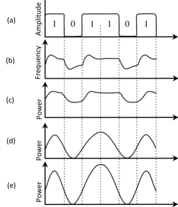
The working principle of transmitter is illustrated in Fig.2. The NRZ PRBS signal generated from the pulse generator is shown in Fig. 2(a). VCSEL frequency-profile (chirp) is shown in Fig. 2(b), adiabatic-chirp is associated with the frequency difference between the space and mark bit levels, whereas transient-chirp is due to bit transitions.
Fig 2: Proposed transmitter operation. (a) NRZ signal from pulse generator, (b) VCSEL frequency-profile (Chirp), (c) VCSEL diode output power, (d) OBPF output power and (e) MZI output power for 101101 bit sequence.
The VCSEL is operating at the far above the threshold point of bias to eliminate the transient chirp. The Adiabatic chirp of VCSEL is 5 GHz. The adiabatic chirp of Δf = 1/2T is used to develop the phase shift of
0
1
2 ( ) 2
2 T
f t dt T
T
at every space bit-period(T). Adiabatic chirp and transient chirp of the VCSEL are controlled by changing the laser device parameters and amplitude of the drive signal. VCSEL frequency modulation (FM) characteristics are generally determined by adiabatic-chirp. VCSEL output power is depicted in Fig. 2(c). Characteristics of OBPF interact with different components of an OC system like VCSEL chirp and dispersion properties of SMF, these results would eliminate the chromatic dispersion in SMF. From Fig. 2(d), the OBPF modify the power signal by the chirp-induced frequency-modulated (FM) data to amplitude-frequency-modulated (AM) data conversion. The key function of optical filter is used to generate chirp-free optical signals except for the center of space bit period; this results in rapid phase shift of π during the middle portion of “0” bit period. Transmission distance and performance of optical system are further enhanced by employing a MZI at the OBPF output. From Fig. 2(e), MZI is employed for amplitude filtering and to increase the output power of the transmitter. Optimum filtering is achieved with the proposed method by adjusting the delay and the coupling ratios in the MZI together with the bandwidth and center-frequency of OBPF.
3.
RESULTS AND DISCUSSION
The effect of optical filtering on the VCSEL diode output facet is analyzed using practical commercial OC system design and Matlab software. 10 Gb/s PRBS NRZ signal having length of 223-1 is generated by pulse generator. The VCSEL model is employed in numerical computations with the following parameters: injection efficiency = 1, quantum efficiency = 0.4, photon life time = 8 ps, differential gain coefficient = 1.0 e-15 cm2, volume of active layer = 80e-12 cm3, gain compression coefficient = 8e-17 cm3, carrier density at
MZI
SMF
GLPF APD NRZ signal
BER analyzer
VCSEL diode Optical filter
[image:2.595.58.280.77.140.2]transparency = 1e17 cm-3,carrier life time = 2 ns, spontaneous emission factor = 1e-6, mode confinement factor = 0.9, line width enhancement factor = 3.2, modulation current = 8 mA and bias current = 9.62 mA. Extinction ratio (ER) of VCSEL is 2.1 dB.
The bandwidths of fourth-order Butterworth and third-order super-Gaussian OBPF are 9 and 9.6 GHz respectively, these filters are operating at 193.414 THz central frequency. MZI delay is set at 38 ps and coupling coefficient of both couplers is 0.22. The SMF utilized in computations with the following parameters: wavelength = 1550 nm, length = 80 km, attenuation = 0.2 dB/km, chromatic dispersion = 16.75 ps/nm/km, nonlinear refractive index = 2.6e-20 m2/W, dispersion slope = 0.075 ps/nm2/km and effective core area = 80 µm2. APD dark current and responsivity are considered to be 10 nA and 1 A/W respectively. GLPF cut-off frequency is positioned at 10 GHz and N is 1.
(a)
[image:3.595.316.539.71.342.2](b)
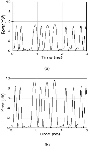
Fig 3: Transmitter output waveforms with Butterworth filter. (a) Without MZI and (b) with MZI for 010100001101011 011000100100101 bit sequence
The output power of transmitter along with Butterworth filter is shown in Fig. 3, the power of the transmitter with MZI is 3 mW high compared to the case of transmitter without MZI; Coupling coefficients and delay of MZI are altered to obtain the highest signal power. The author successfully examined the impact of super-Gaussian OBPF along with MZI on the tailoring of VCSEL output; the result is very nearly same as MZI output that is located at Butterworth OBPF.
(a)
(b) (c)
Fig 4: Optical spectrums of transmitter scheme. (a) VCSEL output, (b) MZI output with super-Gaussian OBPF and (c) MZI output with Butterworth OBPF.
The optical-spectrums of transmitter with MZI are shown in Fig. 4. Optical spectrum analyzer with resolution of 0.08 nm is used for optical-spectrum measurement. It can be seen from Fig. 4 the width of the spectrum at -70 dBm for VCSEL output, super-Gaussian along with MZI and Butterworth along with MZI are 1, 0.2 and 0.3 nm respectively. Optical spectrums at MZI output are much compact in comparison with VCSEL output spectrum this results dispersion tolerance in SMF. The proposed system performance is compared with narrow optical filtering (NOF) [35] scheme. NOF scheme comprises of pulse generator and optical filter along with VCSEL in transmitter.
[image:3.595.90.245.280.534.2]The receiver sensitivities are calculated at BER of 10-9 for NOF scheme at 110 km and transmitter implemented with MZI at 127 km is shown in Fig. 5. The sensitivities of the super-Gaussian together with MZI and Butterworth together with MZI are -26.8 and -26.5 dBm respectively. In the NOF scheme, sensitivities of superGaussian and Butterworth are -26.5 and --26.5 dBm respectively. Sensitivity of the scheme adopted is improved when compared to NOF scheme due to the optimal filtering technique.
[image:3.595.317.547.619.738.2]Fig. 6 shows the BER values for several different lengths of SMF with current approach and NOF based method. BER value of Butterworth along with MZI and super-Gaussian along with MZI is greater than 10-9 after 148 km of SMF. BER value for NOF scheme is larger than 10-9 after 137 km of SMF.
Fig 6: BER performance for several lengths of SMF
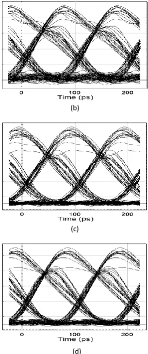
Fig. 7 demonstrates that eye diagram with MZI and NOF schemes after 127 km of SMF. In NOF scheme, eye-opening factors of Butterworth and super-Gaussian are 0.88 and 0.88 respectively. The eye-opening factors of super-Gaussian combined with MZI and Butterworth combined with MZI are 0.9 and 0.92 respectively. Eye-opening is better even after 127 km transmission with the MZI scheme compared to that of NOF scheme. The important parameters of MZI scheme from other previous methods are shown in Table 1.
(a)
(b)
(c)
[image:4.595.351.504.71.437.2](d)
Fig 7: Eye diagrams at 127 km of SMF. (a) NOF with super-Gaussian filter, (b) NOF with Butterworth filter,
(c) super-Gaussian filter along with MZI and (d) Butterworth filter along with MZI
Table 1. Comparison of current work with previous methods
Parameter Butterworth
with MZI
super-Gaussian with MZI
NOF [35]
IDF [25]
VCSEL [23]
fiber length (Km) 127 127 110 45.4 10
bit rate (Gb/s) 10 10 10 4.25 10
laser type VCSEL VCSEL VCSEL VCSEL VCSEL
fiber type SMF SMF SMF SMF and IDF SMF
sensitivity (dBm) -26.8 -26.5 -26.5 -24.5 -17.88
wavelength (nm) 1550 1550 1550 1550 1550
The present approach provides greater transmission distance along with high sensitivity compared to earlier methods.
4.
CONCLUSION
The results confirm that the combination of OBPF and MZI at the output of VCSEL improves performance of SMF link when compared to VCSEL based previous methods. The scheme adopted is used to provide maximum transmission distance and sensitivity in VCSEL based access-networks
without using amplifier.The receiver section of the presented scheme is simple.
[image:4.595.57.284.144.285.2]VCSEL based transmitters with dispersion mitigation technique are necessary for future generation access networks.
5.
REFERENCES
[1] Gábor Fehér, Eszter Udvary, Csaba Fuzy, Tamás Cseh and Tibor Berceli, “Pulsed Mode Red VCSEL for High Speed VLC Communication,” ICTON, 2012, paper We.B4.3.
[2] Ming-Ming Mao, Chen Xu, Qiang Kan, Yi-Yang Xie, Meng Xun, Kun Xu, Jiu-Cheng Liu, Hai-Qiang Ren, and Hong-Da Chen, “High Beam Quality of In-Phase Coherent Coupling 2-D VCSEL Arrays Based on Proton-Implantation,” IEEE Photonics Technology Letters, Vol. 26, No. 4, February 15, 2014, pp.395-397.
[3] Larsson.A, “Advances in VCSELs for Communication and Sensing,” IEEE journal of selected topics in quantum electronics, Vol.17, No.6, Dec. 2011, pp.1552-1567. [4] P. P´erez, A. Valle, I. Noriega, and L. Pesquera,
“Measurement of the Intrinsic Parameters of Single-Mode VCSELs,” Journal Of Lightwave Technology, Vol. 32, No. 8, April 15, 2014, pp.1601-1607.
[5] R. Rodes, J. Estaran, B. Li, M. Muller, J. B. Jensen, T. Gruendl, M. Ortsiefer, C. Neumeyr, J.Rosskopf, K. J. Larsen, M.-C. Amann and I. T. Monroy, “100 Gb/s single VCSEL data transmission link,” in Proc. OFC, 2012, paper PDP5D.10.
[6] M. Malekane Rad, Z. Mazaheri, A. Gholami, Sh.Afyouni Akbari, “4.25 Gb/s Optical Fiber Transceiver for Gigabit Ethernet Applications,” 6th International Symposium on Telecommunications, 2012, pp.520-524.
[7] Fumio Koyama and Tomoyuki Miyamoto, “Recent Advances of VCSEL Technologies,” 2007 International Conference on Indium Phosphide and Related Materials, 2007, pp.420-425.
[8] Hamed Dalir, Akihiro Matsutani, Moustafa Ahmed, Ahmed Bakry, and Fumio Koyama, “High Frequency Modulation of Transverse-Coupled-Cavity VCSELs for Radio Over Fiber Applications,” IEEE Photonics Technology letters, 2014, Vol.26, No.3, pp.281-284. [9] N. Laurand, S. Calvez, M. D. Dawson, S. Bouchoule,
J-C. Harmand, J. Decobert, “1.55-μm Tunable Doped-Fiber Vertical-Cavity Surface Emitting Laser,” Lasers and Electro-Optics 2009 and the European Quantum Electronics Conference , 2009, pp.1
[10]Hubert Halbritter, Cezary Sydlo, Benjamin K¨ogel, Frank Riemenschneider,Hans Ludwig Hartnagel, and Peter Meissner, “Impact of Micromechanics on the Linewidth and Chirp Performance of MEMS-VCSELs,” IEEE Journal Of Selected Topics In Quantum Electronics, Vol. 13, NO. 2, 2007, pp.367-373.
[11]Nikolaos Bamiedakis, Aeffendi Hashim, Richard V. Penty, and Ian H. White, “A 40 Gb/s Optical Bus for Optical-Backplane Interconnections,” Journal Of Lightwave Technology, Vol. 32, No. 8, 2014, pp.1526-1537.
[12]Wayne V. Sorin and Michael R. Tan, “Interoperability of Single-Mode and Multimode Data Links for Data Center and Optical Backplane Applications,” OFC/NFOEC Technical Digest, 2013, paper OW1B.6.
[13] Xiaoxue Zhao, Bo Zhang, Louis Christen, Devang Parekh, Fumio Koyama,Werner Hofmann, Markus C. Amann, Alan E. Willner and Connie J. Chang-Hasnain, “Data Inversion and Adjustable Chirp in 10-Gbps Directly-Modulated Injection-Locked 1.55-μm VCSELs,” OSA / CLEO/QELS 2008, paper CMW5. [14] Wataru Kobayashi, Masakazu Arai, Takayuki
Yamanaka, Naoki Fujiwara, Takeshi Fujisawa, Mitsuteru Ishikawa, Ken Tsuzuki, Yasuo Shibata, Yasuhiro Kondo, and Fumiyoshi Kano, “Wide Temperature (25°C–100°C) Operation of a 10-Gb/s 1.55-µm Electroabsorption Modulator Integrated DFB Laser for 80-km SMF Transmission,” IEEE Photonics Technology Letters, Vol.21, No.15, 2009, pp.1054-1056.
[15] Robert I. Killey, Philip M. Watts, Vitaly Mikhailov, Madeleine Glick, and Polina Bayvel, “Electronic Dispersion Compensation by Signal Predistortion Using Digital Processing and a Dual-Drive Mach–Zehnder Modulator,” IEEE Photonics Technology Letters, Vol.17, No.3, 2005, pp.714-716.
[16] Huaxiang Yi, Qifeng Long, Wei Tan, Li Li, Xingjun Wang, and Zhiping Zhou, “Demonstration of low power penalty of silicon Mach–Zehnder modulator in long-haul transmission,” Optics Express, Vol.20, No.25, 2012, pp. 27562-27568.
[17] Kevin Schires, Antonio Hurtado, Ian D. Henning, and Michael J. Adams, “Polarization and Time-Resolved Dynamics of a 1550-nm VCSEL Subject to Orthogonally Polarized Optical Injection”, IEEE Photonics Journal, Vol.3, No.3, 2011, pp.555-563.
[18] Kengo Koizumi, Masato Yoshida, and Masataka Nakazawa, “A 10-GHz Optoelectronic Oscillator at 1.1 µm Using a Single-Mode VCSEL and a Photonic Crystal Fiber,” IEEE Photonics Technology Letters, Vol.22, No.5, 2010, pp.293-295.
[19] Michael Liu, Mong-Kai Wu, Fei Tan, Rohan Bambery, Milton Feng, Nick Holonyak, “780 nm Oxide-Confined VCSEL With 13.5 Gb/s Error-Free Data Transmission,” IEEE Photonics Technology Letters, 2014, Vol.26, No.7,PP.702-705.
[20] Ioannis Papakonstantinou, Spyridon Papadopoulos, Csaba Soos,Jan Troska, Francois Vasey and Paschalis Vichoudis, “Modal Dispersion Mitigation in Standard Single-Mode Fibers at 850 nm With Fiber Mode Filters,” IEEE Photonics Technology Letters , Vol.22, No.20, 2010, pp.1476-1478.
[21] Ansas M. Kasten, Dominic F. Siriani, Mary K. Hibbs-Brenner, Klein L. Johnson, and Kent D. Choquette, “Beam Properties of Visible Proton-Implanted Photonic Crystal VCSELs,” IEEE Journal Of Selected Topics in Quantum Electronics, Vol. 17, No.6, 2011, PP.1648-1655.
[22] Yi Rao, Weijian Yang, Christopher Chase, Michael C. Y. Huang, D. Philip Worland, Salman Khaleghi, Mohammad Reza Chitgarha, Morteza Ziyadi, Alan E. Willner, and Connie J. Chang-Hasnain,“Long-Wavelength VCSEL Using High-Contrast Grating,” IEEE Journal Of Selected Topics In Quantum Electronics, Vol.9, No.4, 2013, paper 1701311.
Transmission for the Square Kilometre Array (SKA) in South Africa,” In Proceedings of the Southern Africa Telecommunication Networks and Applications Conference (SATNAC), George, South Africa, 2012, pp.483-484.
[24]X. Cheng, Y.J. Wen, Z. Xu, X. Shao, Y. Wang, Y. Yeo, “10-Gb/s WDM-PON Transmission Using Uncooled, Directly Modulated Free-Running 1.55-μm VCSELs,” In proceedings of European Conference on Optical Communication, Brussels, Belgium, 2008, Paper P.6.02. [25]E K Rotich Kipnoo, H Y S Kourouma, R R G Gamatham, A W R Leitch and T B Gibbon, “Chromatic Dispersion Compensation for VCSEL Transmission for Applications such as Square Kilometre Array South Africa,” In Proceedings of the 58th annual SAIP conference,South Africa, 2013, paper 171.
[26]W. Hofmann, L. Grüner-Nielsen, E. Rönneberg, G. Böhm, M. Ortsiefer, and M.-C. Amann, “1.55-µm VCSEL Modulation Performance With Dispersion-Compensating Fibers,” IEEE Photonics Technology Letters, Vol.21, No.15, 2009, pp.1072-1074.
[27]N. Nishiyama, C. Caneau, J. D. Downie, M. Sauer, and C. E. Zah, “10-Gbps 1.3 and 1.55-μm InP-based VCSELs: 85 °C 10-km error-free transmission and room temperature 40-km transmission at 1.55-μm with EDC,” In Proceedings of OFC, 2006, PDP23.
[28]B. Boffi, A. Boletti, A. Gatto, M. Martinelli, “VCSEL to VCSEL injection locking for uncompensated 40-km transmission at 10 Gb/s,” In Proceedings of Optical Fiber Communication Conference, San Diego, USA, 2009, JThA32.
[29] P. V. Mena, J. J. Morikuni, S.-M. Kang, A. V. Harton, and K. W. Wyatt, “A Simple Rate-Equation-Based Thermal VCSEL Model,” Journal Of Lightwave Technology, Vol.17, No.5, 1999, pp.865-872.
[30] Cartledge J C, Burley G S, “The effect of laser chirping on lightwave system performance,” Journal of Lightwave Technology, 1989, Vol.7, No.3, pp.568-573.
[31] Andrew J.Slobodnik, kearns W J and J P Noonan, “Design, fabrication and testing of SAW Butterworth Filters,” IEEE MITTs International Microwave symposium, 1975, pp.353-355
[32] A.J.Slobonik, Fenstermacher T E, W.J.Kearns, George A.Roberts, Silva J H and Joseph P.Noonan, “SAW Butterworth contiguous Filters at UHF,” IEEE transactions on Sonics and Ultrasonics, Vol.SU-26, No.3,1979, pp.246-253.
[33] Martin Pfennigbauer and Peter J. Winzer, “Choice of MUX/DEMUX Filter Characteristics for NRZ, RZ, and CSRZ DWDM Systems,” Journal Of Lightwave Technology, Vol.24, No.4, 2006, pp.1689-1696.
[34] Christi K. Madsen and Jian H. Zhao, “Optical Filter Design and Analysis: A Signal Processing Approach,” John Wiley & Sons, 1999.