Enhanced CSMA/CA Contention Window for Efficient
Random Access in IEEE 802.15.6
Maryam El Azhari, Ahmed Toumanari, Rachid Latif
ESSI, National School of applied Sciences, Ibnou zohr university, Agadir Morocco
ABSTRACT
The IEEE 802.15.6 is a new communication standard on Wireless Body Area Network (WBAN) for short-range, wireless communications in the vicinity of, or inside a human body. It is used for medical and non-medical applications. The IEEE 802.15.6 draft defines a Medium Access Control (MAC) layer compatible with several Physical layers (PHY), it also specifies two main channel access modes; contention based and contention free. This paper aims to mitigate the delay generated by CSMA/CA during the contention based period and thus enhance the network performance in terms of end-to-end delay.
Keywords
IEEE 802.15.6, Scheduled Allocations, Wireless Body Area Network, Wireless Medical Applications, CSMA/CA, contention free, contention based
1.
INTRODUCTION
Recently, Wireless Sensor Networks (WSNs) have evolved the provision of heath care services, for instance, Body Area Networks (BANs) which is a special type of WSNs with short range transmission; have helped in reducing the cost of health care. BANs or WBANs (Wireless Body Area Networks) are composed of a specific number of in-body or/and on-body sensors capable of monitoring medical and non-medical data via a single-hop transmission or multi-hop using relay nodes. A new standard named IEEE 802.15.6 has been developed by many researches from academia and industry to tackle the constraints presented by WBANs with the main focus given to application data. It is developed by IEEE 802.15 Group 6 and has various advantages to other wireless communication standards. IEEE 802.15 standards focus on short range, low complexity, low cost and very low power consumption infrastructures. The main potential of IEEE 802.15.6 is overcoming the limitations of other Personal Area Network (PAN) standards, such as IEEE 802.15.1 and 802.15.4 and allowing wider implementation and deployment of Wireless Body Area Networks (WBANs). IEEE 802.15.1 was the first standard to focus on the short range personal area networking environment and IEEE 802.15.4 traded throughput for low power operation besides it can only meet the lifetime requirements of low rate medical applications [1-2].
2.
IEEE 802.15.6 OVERVIEW
IEEE 802.15.6 is a new standard which main purpose is to improve the performance of health care services in terms of short range communication, higher transfer data rate, lower device complexity, ultra lower power constraint, lifetime, in-body environment, security, Qos, etc. Task group 6 (TG6)
and MAC for short range, low cost and complexity but also ultra-low power and high reliable wireless communication .The IEEE 802.15.6 draft operates with one-hop star and and multi-hop topologies. In the one-hop topology, frames are exchanged between nodes and hubs while in the two-hop restricted tree, a hub and a node may use a relay node to exchange frames. In the following, we will be concentrating on one hop topology. The hubs are responsible for coordinating channel access by establishing one of the three access modes responsible for coordinating channel access:
Beacon mode with beacon period super frame boundaries.
Non-beacon mode with super frame boundaries. Non-beacon mode without super frame boundaries. The time base is composed of multiple superframes corresponding to equal length beacon periods. Each superframe is divided into allocation slots. In beacon and non-beacon modes with superframe boundaries, both nodes and hubs share the same time base sent by the hub enumerating as well the number of allocation slots in it. In the first access mode, the hub communicates the superframe structure via beacon frames or Timed frames (T-Poll). The second access mode does not transmit beacons and the superframe structure is enforced through the use of Timed frames (T-Poll). In the non-beacon mode without superframe boundaries each node establishes its own time base independently. The analysis in this paper concentrates on Beacon Mode with beacon period superframe boundaries [6-8]. The superframe structure, shown in Figure 1, starts with a beacon followed by two consecutive periods each consisting of an Exclusive Access Phase (EAP), Random Access Phase (RAP), Type I/II access phases, and an optional B2 frame that precedes the Contention Access Phase (CAP). It must be noted that the length of these phases is variable and their length is given in numbers of allocation slots. By setting any of these lengths to zero the access phases can be eliminated. This superframe structure allows three types of access:
1. Random access (Contention based): CSMA/CA or Slotted ALOHA for the narrowband and ultra-wide band physical layers respectively.
2. Improvised and unscheduled access: Post (i.e. a hub instruction) or Poll (i.e. a data request from the hub).
Fig 1: IEEE 802.15.6 superframe structure
3.
CSMA/CA FUNCTIONING
MECHANSM OVERVIEW
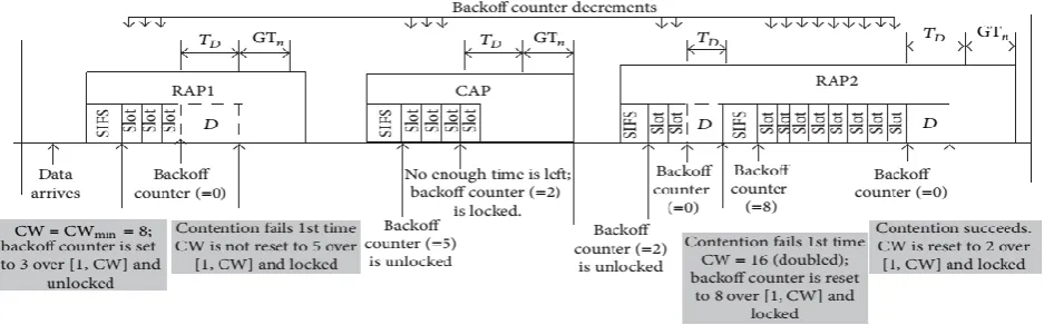
[image:2.595.62.271.74.156.2]The CSMA/CA protocol consists of initializing a backoff counter by each node contending to send data and this is to a random value uniformly distributed over the interval [1,ContentionWindow (CW)], where: CW∈ (CWmin, CWmax). CWmin and CWmax depends on the sensors priorities (Ups), thus, high-priority traffic will have a small contention window and vice-versa in order to speed up the transmission of emergent data towards the destination. Each sensor decrements the backoff counter by one for each idle CSMA slot which length equals to pCSMASlotLength. When the backoff counter reaches zero, the sensor transmits the data otherwise it locks its backoff counter until the channel is once again idle. The CW is doubled for an even number of failures until it reaches CWmax. Figure1 shows an example of the CSMA/CA protocol. As shown in the figure, the node unlocks the backoff counter in RAP1. However, the contention fails and the value of CW remains unchanged because CW does not change for an odd number of failures. In the following CAP period, the backoff counter is set to five; however, it is locked at two because the time between the end of the slot and the end of the CAP is not sufficient to accommodate the data frame transmission and NominalGuard Time (GT ). The backoff counter is then unlocked in the RAP2 period. This time, the value of CW is doubled because there is an even number of contention failures. The backoff counter is set to eight and is unlocked. Once the backoff counter reaches zero, the data are transmitted and the value of CW is set to CWmax [4].
Table 1. UPs and CSMA/CA Contention Window Values
Priority UP Wmin Wmax
Lowest 0 16 64
1 16 32
2 8 32
3 8 16
4 4 16
5 4 8
6 2 8
Highest 7 1 4
4.
ENHANCED CSMA/CA
To our knowledge, we are the first to consider enhancing the performance of CSMA/CA protocol when applied during RAPs in a way to mitigate the transmission delay especially when it comes to data with high priority. As shown in Figure 2, the back off counter in each contention slot is decremented by 1 as soon as it is unlocked. The first contention slot occurs after the channel has been idle for a turnaround inter-frame space (TIFS) and successive contention slots start when the current contention slot ends. Each contention slot has a fixed duration of pSlotLength which equals to: pCCATime + mMACTime + pPHPTime [5], where pCCATime is the time required by the PHP to detect a transmission (or an idle period) and indicate the detection to the MAC. mMACTime is the time required to process and transfer a frame from MAC to PHY layer and finally pPHYTime which corresponds to the time required by PHY to process a frame and transfer it to the air. Based on this concept, a node has to wait an extra time
Fig 2: IEEE 802.15.6 CSMA/CA protocol: slot = CSMA slot SIFS = Psifs, =frame transaction initiated by node 1 in a contended allocation (e.g., a data type frame and an I-Ack frame with pSIFS in between), = time required to complete ,
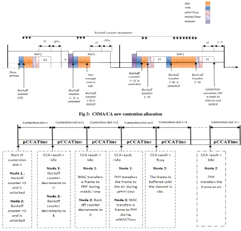
[image:2.595.70.539.508.654.2]Fig 3: CSMA/CA new contention allocation
SET BACKOFF COUNTER ϵ [1, CW]
CHANNEL IS IDLE ? CSMA/CA
BACKOFF COUNTER IS LOCKED
BACKOFF COUNTER IS DECREMENTED
NO
YES
BACKOFF =0 ?
NO
YES
MAC TRANSFERS A FRAME TO PHY
PHY TRANSFERS THE FRAME TO AIR
CONTENTION SUCCESS ?
YES
EVEN NUMBER OF FAILURE? NO
YES
NO
SET CW = 2 * CW
(CW <= CWmax)
CHANNEL IS IDLE ?
PHY PROCESSES THE FRAME
YES
CCA NO
CHANNEL IS
IDLE ? CCA
NO
[image:4.595.118.541.60.719.2]YES
(ET) equals to: backoff counter *( pMACTime + pPHYTime) which varies in respect to backoffcounter value. A big value of this product generates an important delay especially for data with high priority. To resolve this issue, we propose a new structure of time slot where its length is reduced to the time required for data transmission detection (pCCATime). As depicted in Figure 3, each node checks the availability of the
channel during the slot time period (Slot period = pCCATime). Every Time the channel is idle during this
period, the backoff counter is decremented for a successive number of slots until it reaches zero, then the nodes processes the frame and send it to the physical layer during mMACTime, which is then transferred after pPHYTime period to the air.
In our study, we give a theoretical analysis of our new contention allocation schema following different values of pPHYTime and mMACTime in respect to pCCATime. For this reason, we considered two cases of studies where:
pCCATime >= pMACTime + pPHYTime. pCCATime < pMACTime +pPHYTime.
4.1
Case 1:
pCCATime >= pMACTime + pPHYTime In this case, ET period is reduced to pCCATime, and the allocation schema is based as mentioned above on the availability of the channel: each node checks whether the channel is idle or busy and then lock or unlock the backoff counter (Figure 3).4.2
Case 2:
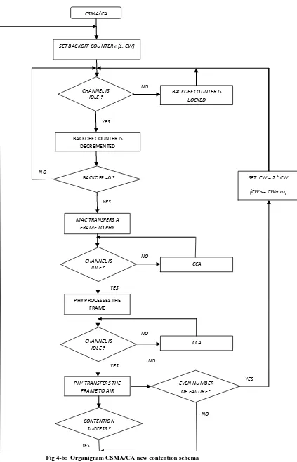
pCCATime < pMACTime + pPHYTime In this case of study, the node has to double check the availability of the channel before proceeding to transmission (see Figure 4-a and Figure 4-b).The backoff counter is set to a sample of an integer random variable uniformly distributed over the interval [1, CW], CW is set to a minimum value (CWmin) for the user priority to be transmitted. It is also reset to this value when additional transmissions remain and contended allocations are needed. The backoff counter is decremented when the channel is idle during pCCATime but locked otherwise, when the backoff counter value reaches zero, the node then proceed to frame processing and transmitting to the physical layer but during this period, the channel might be occupied by another node, a node then has to recheck the availability of the channel before transferring the frame to the air, if the channel is idle then data is transmitted to the destination, otherwise it is buffered until the channel is ready for transmission. Another option could be performing CCA right before transferring the frame through the air, however, this solution will increase data collision since several nodes will attempt to forward data directly to the physical layer and will wait for the channel to be idle before transmission and therefore they will be considered to have the same priority even though their backoff counters are different. A transmission is considered successful when the node receives an expected acknowledgement, However if the node receives a corrupted acknowledgement or receives no acknowledgement at all then it is announced a failure, and as a consequence, the CW is set by alternately doubling the CW value, but not to exceed CWmax for the user priority. Accordingly, following a failed transmission, CW is unchanged, if it was doubled in the last setting; and CW is5.
PERFORMANCE ANALYSIS
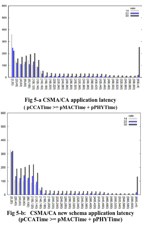
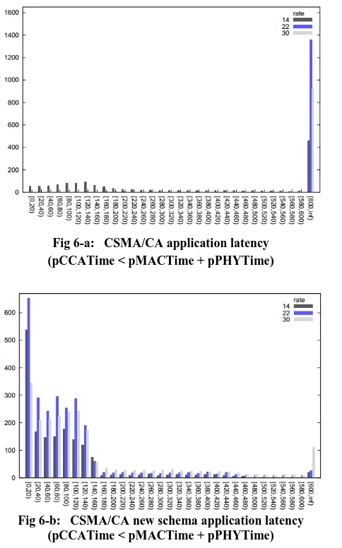
[image:5.595.316.542.406.764.2]In order to highlight the efficiency of our schema, we performed our simulation in Castalia 3.2 designed for Wireless Sensor Networks (WSN), Body Area Networks (BAN), and generally networks of low-power embedded devices [7-9]. We proceeded to analyze the performance of IEEE 802.15.6 in terms of latency when our new CSMA/CA schema is applied during the contention access period. For this purpose we adopted the following parameters: a star topology, bypassRouting for the routing layer (algorithm which does not perform any routing function), and the throughput test application for the application layer. For the physical radio parameters we assumed that the receiver (Rx) sensitivity is -87 dBm and the transmitter power equals -15 dBm. Three cases have been considered to evaluate the effectiveness of our schema. We run our simulation using 12 sensor nodes with predefined locations including the PDA, we used 10 seed sets, and the rate value is respectively: 14, 22, and 30. As can be observed in Figure 5-a and Figure 5-b, our new schema shows a better performance compared with the old one: most of the packet are received under 120 msecs , which means that they are transmitted in the first MAC frame after their creation compared with 600 ms for CSMA/CA ordinary contention allocation. This is something to be expected since the length of mMACTime and pPHYTime exceeds pCCATime, moreover, the big portion of packets with large delay in Figure 5-a and Figure 5-a indicates a potential saturation, with overflown buffers, the same behavior is observed when the length of pCCATime exceeds pPHYTime and mMACTime (See Figure 6-a and Figure 6-b) with the difference that the average latency in the first case is lower than the one in the second case.
Fig 6-a: CSMA/CA application latency (pCCATime < pMACTime + pPHYTime)
Fig 6-b: CSMA/CA new schema application latency (pCCATime < pMACTime + pPHYTime)
6.
CONCLUSION
WBAN provide promising applications in medical monitoring systems to measure specified physiological data and also provide location-based information .In this paper, we presented an enhanced version of CSMA/CA contention allocation schema which mitigates the delay presented by CSMA/CA when used during the RAP/EAP period of IEEE 802.15.6 standards. The simulation results proved the efficiency of our new schema in terms of latency especially for data with high priority where the end-to-end delay is a crucial constraint to resolve. As a future work, we will intend
to use our enhanced schema to perform data transmission using relay nodes so that the energy consumption generated by star topology can be reduced to some extent, and so is the end-to-end delay which is expected to get smaller value compared with the original schema.
7.
REFERENCES
[1] M. El azhari, A.Toumanari and R.Latif. ”Study of MAC Protocols for Mobile Wireless Body Sensor Networks”, 2014, International Journal of Network and Complex Systems.
[2] Tachtatzis, C. “An energy analysis of IEEE 802.15.6 scheduled access modes”, GLOBECOM Workshops (GC Wkshps), 2010 IEEE.
[3] Standard,Kyung S.Kwak, S.Ullah, and N.Ullah ,”An Overview of IEEE 802.15.6 ,” UWB -ITRC Center, Inha University,253 Yonghyun-dong, Nam-gu, Incheon (402-751), South Korea.2010.
[4] Sana Ullah,Manar Mohaisen, Mohammed A. Alnuem “A Review of IEEE 802.15.6 MAC, PHY, and Security Specifications”, International Journal of Distributed Sensor Networks Volume 2013, Article ID 950704, 12 pages ,http://dx.doi.org/10.1155/2013/950704
[5] Jin-Meng Ho, Plano, TX, “ SMART ADJUSTMENT OF BACKOFF COUNTER AND CONTENTION WINDOW FOR IMPROVED RANDOM ACCESS”, US 20100195664 A1, august 2014.
[6] Carlos Pomalaza-Ráez and Attaphongse Taparugssanagorn , “The UWB Channel in Medical Wireless Body Area Networks (WBANs)”, http://dx.doi.org/10.5772/48634.
[7] Castalia website:http://castalia.npc.nicta.com.au/ [8] K.Kwak, S.Ullah, and N.Ullah , “An Overview of IEEE
802.15.6 Standard ”,UWB-ITRC Center, Inha University 253 Yonghyun-dong, Nam-gu, Incheon (402-751), South Korea,20 Feb 2011.
[image:6.595.56.285.75.229.2]