Multi-user Detection by MMSE Adaptive Algorithm
for Multi-Beam-MIMO-MC-CDMA using
Sequences of References
Mourad Benyarou
Abou-Bekr Belkaid University,
Faculty of Technology,
Telecommunications laboratory
P.O. Box 230, Tlemcen, Algeria
Fethi Tarik Bendimerad
Abou-Bekr Belkaid University,
Faculty of Technology,
Telecommunications laboratory
P.O. Box 230, Tlemcen, Algeria
Fatima Debbat
Mustapha stambouli University,
department of computer
science
P.O. Box 305,Mascara, Algeria
ABSTRACT
The main objective of the multi-antenna technology is improving the capacity of cellular systems. These techniques can also make other improvements such as the scope of the system, reducing the transmission power of mobile (and therefore increasing energy autonomy) and improved link performance. This was the context of this paper study whose objective was to study the contribution and providing of the use of adaptive antennas in multiuser detection for MC-CDMA system. Transmission implicated in the MC-CDMA system has potential interference rejection but not sufficiently in the case of strong interference. Therefore it need to use beamforming algorithms. This work is also interested in MIMO-MC-CDMA with multiple-beamforming (MBF) at the receiver, that uses multiple antennas at transmitter and receiver. This paper presents also the performance of general MIMO-MC-CDMA system used Multi-Beamformer with sequences of references at receiver and space time block code (STBC) or vertical bell labs space-time architecture (V-BLAST) at the transmitter, with minimum mean square error (MMSE) adaptive algorithm under Rayleigh fading channels.General Terms.
Multiplexing, diversity, beamforming, multicarrier, performance
Keywords
:
MC-CDMA, MIMO, VBLAST, STBC, Multiuser detection,Multi-beamforming, MMSE Adaptive Algorithm.
1. INTRODUCTION
The optimization of new transmission techniques which provide robustness and high spectral efficiency is crucial to the development of future cellular networks for radio-communication. Like the success achieved in recent years by the multi-carrier modulation techniques which is based on OFDM and CDMA, the innovative techniques of transmission MC-CDMA are emerging today as candidate solutions for fourth generation cellular networks [1-2] with robustness potential of multi-carrier modulation on the one hand and flexibility in the sharing of radio resources for CDMA on the other hand.MC-CDMA techniques have improved significantly the ability of these future networks [3-4]. Meanwhile, another promising approach is to exploit spatial diversity or spatial
multiplexing using multiple antennas at both the transmitter and the receiver, this approach is called MIMO systems.
The purpose of this paper is to study the association of MC-CDMA and MIMO systems in order to exploit the spatial diversity or spatial multiplexing at transmitter with multi-beam at receiver. Multiuser detection is presented in the case of uplink for cellular systems.
2. MC-CDMA SIGNAL
In the MC-CDMA modulator shown in Figure 1, the data stream is first coded, interleaved and modulated into symbols x
by BICM block, and then the stream obtained is spread in the frequency domain using a spreading code and converted in sub-streams by the serial to parallel converter and transmitted on different sub carriers of the OFDM multiplex. A portion of each original data, corresponding to a chip of the spreading code with length 𝐿𝑐, is thus transmitted by each of the 𝑁𝑐 sub
carriers.
Fig1: Modulator MC-CDMA
In the case of a downlink where the various signals targeting different users are transmitted synchronously, the codes used are generally selected orthogonal, which results in receiving a better rejection of interference between users. Thus, with Walsh-Hadamard codes, the maximum number of users equals the number of codes. Generally, the number of 𝐿𝑐 chips of the
spreading code is chosen equal to the number 𝑁𝑐 of subcarriers [5-6] but variants are possible to better adapt the signal to the channel in the case of an OFDM symbol by using an operation of inverse Fourier transform.
𝐜
𝑗𝑑
𝑗𝑥
𝐬
𝑗BICM
3. TRANSMITTER WITH MIMO
MAPPING
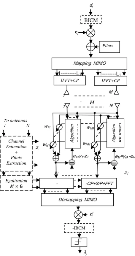
Figure 2 shows the block diagram of an MC-CDMA transmitter with MIMO mapping and Multi-beamforming at the receiver.
First, the data input 𝑑𝑗 for the 𝑗𝑡ℎ user is modulated into a
symbol x with a BICM (Bit Interleaved Coded Modulation) encoder. Next, Mapping MIMO takes a block of modulated symbols and maps them into orthogonal sequences of length 𝐿1
[image:2.595.54.282.193.625.2].
Fig 2: MBF-MIMO-MC-CDMA with spatial multiplexing or spatial diversity.
Let 𝐱𝑖 be an 1× 𝐿1 symbol sequence for the 𝑖𝑡ℎ transmit
antenna given by
𝐱𝑖= 𝑥𝑖1,…,𝑥𝑖𝐿1 , 𝑖 = 1 … , 𝑀
Then for all antennas at transmitter it has
𝐗 =
𝑥11 ⋯
⋮ ⋱ 𝑥1𝑙1
⋯ 𝑥1𝐿1
⋮ ⋰ ⋮ 𝑥𝑖1 ⋮
⋮ 𝑥𝑀1
⋰ ⋯
𝑥𝑖𝑙1 ⋮ 𝑥𝑖𝐿1
⋮ 𝑥𝑖𝑙1
⋱ ⋯
⋮ 𝑥𝑀𝐿1 𝑀×𝐿1
(1)
Where 𝑀is denoted as the number of transmit antennas. Note that in the STBC case the orthogonality of the sequences enables to achieve the full transmit diversity for any number of transmit antenna and allows the receiver to decouple the signals transmitted from different antennas. Before transmitting, the MC-CDMA performs spreading, IFFT and cyclic prefix adding to avoid ISI as shown in Figure 2.
The radiated sequence can be modeled as
𝑠𝑖𝑗 𝑙1 𝑛 =
1
𝑁𝑐 𝜀𝑗
𝑁𝑐−1
𝑝=0 𝑥𝑖𝑙1𝑐𝑗 𝑝 exp
𝑗2𝜋𝑝𝑛
𝑁𝑐 (2)
𝑛 = 0,1, … , 𝑁𝑐− 1
𝐬𝑖𝑗 𝑛 = 𝑠𝑖𝑗 1 𝑛 𝑠𝑖𝑗 2 𝑛 … 𝑠𝑖𝑗 𝐿1 𝑛 1×𝐿
1 (3)
Where 𝐬𝑖𝑗 𝑛 represents the 𝑛𝑡ℎ sub channel sequence of the
𝑗𝑡ℎuser that is transmitted by the 𝑖𝑡ℎ antenna ;𝑁
𝑐 = 𝑁𝑒=𝑇𝑇𝑠
𝑐=
𝐿𝑐 ; 𝑁𝑐 , 𝑁𝑒, 𝑇𝑠, 𝑇𝑐 and 𝐿𝑐 are respectively a number of subcarrier , the processing gain as a consequence of spreading ,time symbol ,time chip and code length , 𝑐𝑗 𝑝 is the 𝑝𝑡ℎchip
of the code sequence and 𝜀𝑗is the energy per symbol for the
𝑗𝑡ℎuser.
In the MIMO channel, consider a scenario where there are 𝑁𝑈
users communicating synchronously with a common base station. Each user station (mobile station) has 𝑀 transmit antennas and the base station has 𝑁receive antennas.
First we consider the Figure 3
Fig 3: Principle illustrating the estimation of symbols
N k
wkf
S/P
𝑠𝑖𝑗𝑙1 𝑛
i 1 1
M
𝑟𝑘𝑓(𝑛)
𝑦𝑓 𝑛
Cp
𝜃
zf
ef
𝑟𝑘(𝑛)
bk
𝑒𝑓=𝑧𝑓− 𝑦𝑓
f-th
BF Adaptive Algorithm
𝑟𝑘(𝑓+1)(𝑛)
𝑟𝑘(𝑓−1)(𝑛)
IF
FT+
C
P
𝑦𝑘𝑓′ (𝑛)
𝑠𝑖𝑗𝑙1 𝑝
Al
go
rithm
BF
-SI
IMO
-IBCM
H
PilotseM=yM –zM
e1=y1-z1
w1M
y1 z1
yM zM
Démapping MIMO W11
𝑑 𝑗
1
dj
cj
𝐜𝑗𝑇
1 N
M
wNM
Al
go
rithm
BF
-SI
IMO
FF
-MIMO
Alg
ori
thm
e
de FF
-MIMO
w11
1---L1 IFFT+CP
1---L1 IFFT+CP
Mapping MIMO
-CP+S/P+FFT
BICM
Egalisation 𝑀 × 𝐆
z1
zM To antennas
1 N
Channel Estimation
+ Pilots Extraction
-CP+S/P+FFT
[image:2.595.316.562.595.718.2]The received signal from the jth user and L propagation paths at the output of kth antenna is expressed as:
𝐫𝑗𝑘 𝑛 = 𝑎𝑘𝑗 𝜃 ℎ𝑘𝑖 𝑛, 𝑙 𝑠𝑖𝑗𝑙1 𝑛 − 𝑙
𝐿1 𝑙1=1
𝐿−1 𝑙=0 𝑀
𝑖=1 + 𝐧(n)
(4)
Where 𝑠𝑖𝑗𝑙1(n) is defined by (2) and ℎ𝑘,𝑖,𝑙
𝐿−1 𝑙=0 𝑒
−𝑗 2𝜋𝑙𝑝 𝑁𝑐 =
ℎ𝑘𝑖,𝑝 = 𝜌𝑘𝑖,𝑝𝑒𝑖𝜃𝑘𝑖 ,𝑝, 𝑝 = 0, … , 𝐿𝑐− 1
ℎ𝑘𝑖,𝑝 is the Fourier transform at element ℎ𝑘,𝑖,𝑙of the matrix of
the MIMO multipath Channel for the pth sub carrier.
For all antennas reception at instant n we have :
𝐑𝑗 𝑛 = 𝑁𝑘=1𝐫𝑗𝑘(𝑛)=
(𝐀𝑗⨀𝐇𝑝)𝐒
𝑗(𝑛) + 𝐍(𝑛) (N×𝐿
𝑐)×(1×L1) (5)
𝑛 = 0,1, … , 𝑁𝑐− 1
Where 𝐇𝑝= 𝑁𝑘=1 𝑀𝑖=1ℎ𝑘𝑖 ,𝑝 (𝑁×1)×(𝑀×1) is the matrix
channel for the pth sub carrier.
𝐒𝑗 𝑛 = 𝐹𝐹𝑇−1( 𝜀𝑗𝐗𝑐𝑗 𝑝 )
𝐒𝑗 𝑛 = 𝐬1𝑗1 𝑛 ⋯ 𝐬𝑖𝑗 𝑙1 𝑛 ⋯ 𝐬𝑀𝑗 𝐿1(𝑛) 𝑀×𝐿1
𝑇
(6)
𝐗𝑐𝑗 𝑝 =
𝑥11𝑐𝑗 𝑝 ⋯
⋮ ⋱
𝑥1𝑙1𝑐𝑗 𝑝 ⋯ 𝑥1𝐿1𝑐𝑗 𝑝
⋮ ⋰ ⋮
𝑥𝑖1𝑐𝑗 𝑝 ⋮
⋮ 𝑥𝑀1𝑐𝑗 𝑝
⋰ ⋯
𝑥𝑖𝑙1𝑐𝑗 𝑝 ⋮ 𝑥𝑖𝐿1𝑐𝑗 𝑝
⋮ 𝑥𝑖𝑙1𝑐𝑗 𝑝
⋱ ⋯
⋮
𝑥𝑀𝐿1𝑐𝑗 𝑝 𝑀×𝐿
1
The output for all antennas and all users at base station is given
by
𝐑 𝑛 = 𝑁𝑗 =1𝑈 𝐑𝑗(𝑛) = 𝐫1(𝑛) ⋯ 𝐫𝑁(𝑛) (N×1)×(L𝑇 1×1)
= (𝐀 θ ⨀𝐇𝑝)𝐒(𝑛) + 𝐍 𝑛 (7)
𝐒 𝑛 = 𝑁𝑗 =1𝑈 𝐒𝑗 𝑛 = FFT−1 𝛆𝐗𝐜(𝑝) (8)
𝐗𝐜 𝑝 =
𝑥11𝐜 𝑝 ⋯
⋮ ⋱ 𝑥1𝑙1𝐜 𝑝 ⋯ 𝑥1𝐿1 𝐜 𝑝
⋮ ⋰ ⋮
𝑥𝑖1𝐜 𝑝 ⋮
⋮ 𝑥𝑀1𝐜 𝑝
⋰ ⋯
𝑥𝑖𝑙1𝐜 𝑝 ⋮ 𝑥𝑖𝐿1𝐜 𝑝
⋮ 𝑥𝑖𝑙1𝐜 𝑝
⋱ ⋯
⋮ 𝑥𝑀𝐿1𝐜 𝑝 𝑀×𝐿
1
𝐜(𝑝) = 𝑐1(𝑝) ⋯ c𝑗(𝑝) ⋯ c𝑁𝑈(𝑝) 1×𝑁𝑈
and 𝑥𝑖𝑙1𝐜 𝑝 = 𝑁𝑗 =1𝑈 𝑥𝑖𝑙1c𝑗(𝑝)
𝐀𝑗 θ = 𝐚 𝜃
1𝑗 𝐚 𝜃2𝑗 ⋯ 𝐚 𝜃𝑀𝑗 𝑁×𝑀 (9)
𝐚 𝜽𝒊𝒋 = 1 𝑒𝑗2𝜋
𝑑
𝜆𝑠𝑖𝑛 𝜃𝑖𝑗⋯ 𝑒𝑗2𝜋 𝑑
𝜆(𝑁−1)𝑠𝑖𝑛 𝜃𝑖𝑗
𝑁×1 𝑇
𝐍 𝑛 = 𝐁 𝑛 + 𝐈(𝑛) (10)
𝐁 𝑛 = 𝐛1 𝑛 𝐛2 𝑛 ⋯ 𝐛𝑁 𝑛 𝑁×1 ×(𝐿1×1)
𝑇
𝐈 𝑛 = 𝑖1 𝑛 𝑖2 𝑛 ⋯ 𝑖𝑁 𝑛 𝑁×1𝑇
⨀
is an operator of multiplying element by element or called Hadamard product. In the steering vector 𝐚 𝜽𝒊𝒋 , d is theinter-element antenna spacing; 𝜆is the wavelength and 𝜃𝑖𝑗 is the
direction of arrival (DOA) of the 𝑗𝑡ℎ user coming from the 𝑖𝑡ℎ antenna as shown inFigure 3. The matrix
𝐇
(𝑁×1)×(𝑀×1)is a channel coefficient matrix for all paths. The coefficient amplitude is determined by the Rayleigh random variable while its phase is uniformly distributed in the interval 0 − 2𝜋 . 𝐁 𝑛 is temporally and spatially uncorrelated Gaussian noise vector with zero mean and complex variance 𝜍𝑏2 and 𝐈 𝑛 is theinterference vector on all antennas reception.
It assumed that each path of each user incidents on the receive antenna array arrives with the same DOAs.
Note that by removing the cyclic prefix at the beginning of each received data block, the inter-symbol OFDM interference can be eliminated.
For all users and for 0 ≤ 𝑝 ≤ (𝑁𝑐= 𝐿𝑐) and 0 ≤ 𝑛 ≤ 𝐿𝑐 R is
given by
𝐑 = (𝐀 θ ⨀𝐇)𝐒 + 𝐍 (N×𝐿𝑐)×(L1×𝐿𝑐) (11)
𝐒 = 𝐹𝐹𝑇−1( 𝜀
𝑗 𝐗𝐂) (𝑀×𝐿
𝑐)×(𝐿1×𝐿𝑐)
𝐗𝐂 =
𝑥11𝐂 ⋯
⋮ ⋱ 𝑥1𝑙1𝐂 ⋯ 𝑥1𝐿1 𝐂 ⋮ ⋰ ⋮ 𝑥𝑖1𝐂 ⋮
⋮ 𝑥𝑀1𝐂
⋰ ⋯
𝑥𝑖𝑙1𝐂 ⋮ 𝑥𝑖𝐿1𝐂
⋮ 𝑥𝑖𝑙1𝐂
⋱ ⋯
𝐂 = 𝐜0⋯ 𝐜𝑗⋯ 𝐜𝑁𝑈 −1 𝐿𝑐×𝑁𝑈
𝑥𝑖𝑙1𝐂 = 𝑥𝑖𝑙1
𝑁𝑈
𝑗 =1 𝐜𝑗
𝐜𝑗 = 𝑐𝑗(0) ⋯ 𝑐𝒋(𝑝) ⋯ 𝑐𝒋(𝐿𝑐− 1) 𝐿
𝑐×1
𝑇
𝐇 = 𝑁𝑘=1 𝑀𝑖=1𝐇𝑘𝑖 (𝑁×𝐿𝑐)×(𝑀×𝐿𝑐)
𝐇𝑘𝑖=
ℎ11,𝑝 0
0 ℎ22,𝑝
⋯ 0
⋯ 0 ⋯ 0⋯ 0 ⋮ ⋮
0 0 ⋮ 0 0⋮
⋮ ⋮ ⋯ ℎ𝑘𝑖,𝑝
⋮ ⋯ 0⋮
⋮ ⋮
⋯ 0
⋮ ⋯
⋮ ℎ𝑁𝑐𝑁𝑐,𝑝 𝑁𝑐×𝑁𝑐
𝐇𝑘𝑖 is a diagonal matrix of size 𝐿𝑐× 𝐿𝑐 where each diagonal
element corresponding to the channel frequency response at the subcarrier p, ℎ𝑘𝑖 ,𝑝= 𝜌𝑘𝑖𝑝𝑒𝑖𝜃𝑘𝑖 ,𝑝 whose coefficient 𝜌𝑘𝑖𝑝 is a
magnitude determined by a random variable Rayleigh and 𝜃𝑘𝑖,𝑝
is the phase uniformly distributed in the interval 0 − 2𝜋 .
𝐍 = 𝐁 + 𝐈
𝐁 = 𝐁1 𝐁2⋯ 𝐁𝑁 𝑁×𝑁𝑐 ×(𝐿1×𝑁𝑐)
𝑇
𝐈 = 𝑖1 𝑖2⋯ 𝑖𝑁 𝑁×1𝑇
The reception matrix R consists of 𝑙1 columns 𝐕𝑙1. The
columns 𝐕𝑙1 can be rewritten in time series as:
𝐕𝑙1= 𝐕𝑙1 0 ⋯ 𝐕𝑙1(𝑛) ⋯ 𝐕𝑙1(𝐿𝑐− 1) N×𝐿𝑐 ×(1×𝐿𝑐) (12)
For despreading the received data, each column vector
𝐕𝑙1 𝑙1= 0, … , 𝐿1− 1 is multiplied by a Fourier matrix F, then
the result give:
𝕏𝑙1(𝑁×𝐿𝑐)= 𝐕𝑙1𝐅𝐿𝑐×𝐿𝑐 (13)
Where 𝐅𝐿𝑐×𝐿𝑐 is the FFT and is given as
𝐅 =𝐿1
𝑐
1 1
1 𝑒−𝑗2𝜋 1 1 /𝐿𝑐
⋮ ⋮ 1 𝑒−𝑗2𝜋 𝐿𝑐−1 (1)/𝐿𝑐
⋯ 1
⋯ 𝑒−𝑗2𝜋(1)(𝐿𝑐−1)/𝐿𝑐
⋱ ⋮
⋯ 𝑒−𝑗2𝜋 𝐿𝑐−1 (𝐿𝑐−1)/𝐿𝑐 𝐿 𝑐×𝐿𝑐
Then multiplied each row of 𝕏𝑙1 by the code sequence give:
𝕏𝑗 𝑙1= 𝑟𝑜𝑤(𝕏𝑙1)⨀𝐜𝑗
𝑇 (14)
[image:4.595.312.550.132.319.2]The method and the proposed adaptive beamforming are explained in the following subsections
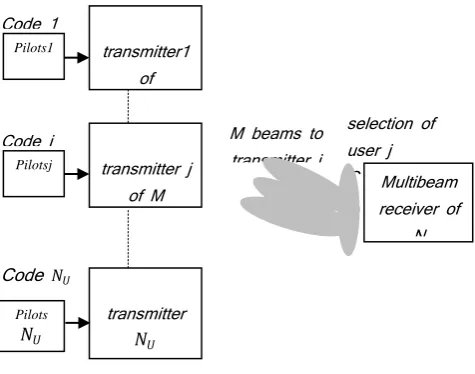
Fig 4 : Multiuser detection with multibeam systems
3.1
CDMA case
In the CDMA case the same equations are obtained but it need to omit the IFFT operation in eq (2) and IFFT /FFT in Figure 2 and replacing eq (2) by (15) and the H matrix is replaced by an multipath channel with (𝑁 × 𝐿) × 𝑀 dimension, 𝐿 is the number of paths:
𝑠𝑖𝑗 𝑙1 𝑛 = 𝜀𝑗𝑥𝑖𝑙1𝑐𝑗 𝑝 (15)
After, this equation is used for all the following.
4.
BEAMFORMING ALGORITHM
This paper presents the multiuser detection with multibeam.
The M beams of the base station is directed to the M antennas
of each mobile as illustrated in Figure 4
Our adaptive algorithm is an MMSE algorithm with signal reference (pilot).This pilots are inserted for each antennas at transmitter. This adaptive algorithm is used for all Beamformer at receiver.
The error signal as chow on figure 3 is given by [7-8-9]
𝑒𝑓 𝑛 = 𝑦𝑓 𝑛 − 𝑧𝑓 𝑛
(16)
The index f is for the f-th beamformer (see Figure 2 or 3) and
𝑦𝑓 𝑛 is the estimated of 𝑠𝑖𝑗𝑙1𝑖(𝑛) because in this case the beam
f is directed to the transmitting antenna i for user j.
𝐰𝑗𝑓
= 𝐰𝑆𝐵
𝑓= 𝑤
𝑗𝑓 1⋯ 𝑤𝑗𝑓𝑘
⋯ 𝑤
𝑗𝑓𝑁 𝑁×1 𝑇,
𝑘 = 1, ⋯ , 𝑁transmitter j of M antennas transmitter1
of M antennes
selection of user j Code j Code 1
Code j
Code 𝑁𝑈
M beams to transmitter j
Multibeam receiver of
N antennas
transmitter
𝑁𝑈
of M antennas Pilots1
Pilotsj
Pilots
is called a Simple Beam weight vector number f corresponding
for user j and N is the number of antennas at the reception.
The weights of the vector 𝐰𝑗𝑓 are calculated according to the
reference signal 𝑧𝑓(⟺ 𝑧𝑖 which is multiplexed with the i-th
IFFT and injected into the transmitter antenna i of the jth user).
Figure 3 is a subassembly of Figure 2, ie to allow the detection
of only one symbol 𝑠𝑖𝑗𝑙1 𝑛 by the beamformer f at time n, then
to detect all symbols 𝑦𝑓 , 𝑓 = 1, ⋯ , 𝑀, M equations are
obtained of the form:
𝑦1 𝑛 = 𝑁𝑘=1𝑤𝑗𝑘 1∗ 𝑟𝑗1 𝑛 − 𝑘 is the estimated of 𝑠1𝑗𝑙1 𝑛
𝑦2 𝑛 = 𝑁𝑘=1𝑤𝑗𝑘 2∗ 𝑟𝑗2 𝑛 − 𝑘 is the estimated of 𝑠2𝑗𝑙1 𝑛
⋮
𝑦𝑓 𝑛 = 𝑁𝑘=1𝑤𝑗𝑘 𝑓∗ 𝑟𝑗𝑓 𝑛 − 𝑘 is the estimated of 𝑠𝑖𝑗𝑙1 𝑛
⋮
𝑦𝑀 𝑛 = 𝑁𝑘=1𝑤𝑗𝑘 𝑀∗ 𝑟𝑗𝑀 𝑛 − 𝑘 is the estimated of 𝑠𝑀𝑗𝑙1 𝑛
Then for index i,
𝑠 𝑖𝑗𝑙1 𝑛 = 𝑦𝑓 𝑛 = 𝑤𝑗𝑘𝑓 𝑟𝑗𝑓 𝑛 − 𝑘
𝑁
𝑘=1 = 𝐰𝑗𝑓𝐻𝐫𝑗𝑓 𝑛 (17)
Then for all symbols (or for all M antennas) andfor all users at time n:
𝐒 𝑛 = 𝐖𝑀𝐵𝑀𝑈𝐻 𝐑(𝑛) 𝑀×𝐿1
The formation of multiple beams is used to eliminate interferences on antennas array at reception, in neglecting the
noise B(n) for simplifying the previous equation can be written
as:
𝐒 𝑛 = 𝐖𝑀𝐵𝑀𝑈𝐻 𝐀 θ ⨀𝐇𝐒(𝑛) 𝑀×𝐿1 (18)
𝐖𝑀𝐵𝑀𝑈 is called Multi-Beam Multi-User weighting matrix and
𝐒(𝑛)is defined by (8).
- j is omittedfor all next equations for convenience. In the MMSE approach, the cost function to minimized is
𝑱 𝑤𝑓 = E 𝐰𝑓𝐻𝐫𝑓 𝑛 − 𝑧𝑓(𝑛) 2
(19)
Where 𝑧𝑓 𝑛 = 𝑧𝑓(𝑛𝑇𝑠) and 𝐫𝑓 𝑛 = 𝐫𝑓 𝑛𝑇𝑠 where 𝑇𝑠 is the
sampling period .
The cost function is the expected value (taken over the ensemble of realizations of 𝐫𝑓 𝑛 ) of the square error between
the array output and the desired version of that signal at time index n. (18) can be rewrite as :
𝑱 𝑤𝑓 = 𝐰𝑓𝐻E 𝐫𝑓 𝑛 𝐫𝑓𝐻(𝑛) 𝐰𝑓− E 𝑧𝑓(𝑛)𝐫𝑓𝐻(𝑛) 𝐰𝑓−
𝐰𝑓𝐻E 𝐫𝑓 𝑛 𝑧𝑓∗(𝑛) + E 𝑧𝑓(𝑛)𝑧𝑓∗(𝑛) (20)
In general, the vector function is minimized by determining a location where the gradient of the function goes to zero, then the solution is given by :
∇𝐽 𝑤𝑓 = 2𝐑𝐰𝑓− 2𝐫𝑟𝑠𝑖 (21)
Where R is the correlation matrix of the data vector
𝐑 = E 𝐫 𝑛 𝐫𝐻(𝑛) (22)
and 𝐫𝑟𝑠𝑖is the cross-correlation vector between the data vector
and the desired signal,
𝐫𝑟𝑠𝑖 = E 𝐫 𝑛 𝑠𝑖
𝐻(𝑛) (23)
Setting the gradient of the cost function equal to zero, the solution for 𝐰𝑓wich minimizes 𝑱 𝑤𝑓 is given by
𝐰𝑓 = 𝐑−1𝐫𝑟𝑠𝑖 (24)
The first step is to realize a deterministic iterative procedure to compute 𝐰𝑓 𝑜𝑝𝑡.It can see this method avoids the computation of the inverse 𝐑−1.
For this problem the steepest descent or gradient algorithm methods is used and is defined by,
𝐰𝑓 𝑘 + 1 = 𝐰𝑓 𝑘 −12𝜇∇𝐰𝑓 𝑘 𝑱(𝑘) (25)
Where ∇𝑤𝑓 𝑘 denotes the gradient of 𝑱 𝑘 with respect to 𝐰𝑓,𝜇
is the adaptation gain ,a real valued positive constant ,and k is the iteration index , in general not necessarily coinciding with time instants.
As 𝐽(𝑘)is a quadratic function of the vector coefficients, the solution is given by:
∇𝐰𝑓 𝑘 𝐽 𝑘 = 2(𝐑𝐰𝑓 𝑘 − 𝐫𝑟𝑠𝑖) (26)
hence
In the scalar case, for real-valued signals in [7] page 171 𝜇𝑜𝑝𝑡is
defined as 𝜇𝑜𝑝𝑡 =𝜆 2
𝑚𝑎𝑥+𝜆𝑚𝑖𝑛where𝜆𝑚𝑎𝑥and 𝜆𝑚𝑖𝑛 are the
eigenvalues of 𝚲 when using decomposition 𝐑 = 𝐔𝚲𝐔H and
𝐔 is the unitary matrix formed of eigenvectors of R.
5. SIMULATION RESULTS
The performance of the proposed algorithm is evaluated by simulating BERs (bit error rates).
Figure 2 is considered, two antenna arrays are uniform and
linear with a half-wavelength inter-element spacing, M
elements at the transmitter and N elements at the receiver.The
number of users is 𝑁𝑈= 4. Each user is assigned 8 paths and
come with almost the same angle incidenceθ.
The signal to noise ratio of Co-channel interference is low compared to that of the signal of interest and is uniformly distributed in the interval [0,15] dB and their directions are
uniformly distributed in the interval [-70.70].
To generate the spreading codes the Hadamard matrix is used,
the number of chips𝐿𝑐 is equal to the number of subcarrier𝑁𝑐=
128.
To generate the pilot sequence 𝑧𝑓, 𝑓 = 1, ⋯ , 𝑀 of each
beamformer one OFDM symbol is inserted in each frame of the IFFT for MC-CDMA systems. The guard interval is selected equal to one quarter of the OFDM symbol duration.
In the MC-CDMA case the number of OFDM symbol in the frame is selected as a function of the length of the sequence of
the S matrix and is equal to 𝑁𝑓𝑟≥ (𝐿1+ 1), 𝐿1 is the length of
the sequence of the S matrix, 1 represents an OFDM symbol of
the reference sequence.
In the CDMA case after each sequence of the matrix S a PN
sequence is used as a reference signal.
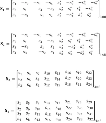
Spatial diversity is considered with two matrix𝐒1 or 𝐒2 for
STBC encoder and spatial multiplexing with two matrix 𝐒3or𝐒4
for VBLASTencoder.
Bpsk is used for the STBC modulation case and 16 QAM in the VBLAST case.
𝐒1=
𝑠1 −𝑠2 −𝑠3 −𝑠4 𝑠1∗ −𝑠2∗ −𝑠3∗ −𝑠4∗
𝑠2 𝑠1 𝑠4 −𝑠3 𝑠∗2 𝑠1∗ 𝑠4∗ −𝑠3∗
𝑠3 −𝑠4 𝑠1 𝑠2 𝑠3∗ −𝑠4∗ 𝑠1∗ 𝑠2∗ 3×8
𝐒2=
𝑠1 −𝑠2 −𝑠3 −𝑠4 𝑠1∗ −𝑠2∗ −𝑠3∗ −𝑠4∗
𝑠2 𝑠1 𝑠4 −𝑠3 𝑠2∗ 𝑠1∗ 𝑠4∗ −𝑠3∗
𝑠3
𝑠4
−𝑠4
𝑠3
𝑠1
−𝑠2
𝑠2
𝑠1
𝑠3∗ −𝑠4∗ 𝑠1∗ 𝑠2∗
𝑠4∗ 𝑠3∗ −𝑠2∗ 𝑠1∗ 4×8
𝐒3=
s1 s4 s7 s10 s13 s16 s19 s22
s2 s5 s8 s11 s14 s17 s20 s23
s3 s6 s9 s12 s15 s18 s21 s24 3×8
𝐒4=
s1 s5 s9 s13 s17 s21 s25 s29
s2 s6 s10 s14 s18 s22 s26 s30
s3
s4
s7
s8
s11
s12
s15 s19 s23 s27 s31
s16 s20 s24 s28 s32 4×8
For these simulations it was assumed that different subcarriers for the MC-CDMA system are multiplied by independent Rayleigh fading non-selective for each subcarrier and perfectly esteemed. The signals of all users are received with the same average power.
The bandwidth of our channel is equal to 1.25 MHZ. For OFDM (IFFT) the width is divided into 256 subchannels. Four subchannels are used as guard interval, the others are used as
data. Duration of an OFDM symbol is 225μs. The 20.8 𝜇𝑠are
used for the guard interval, for the removal of the intersymbol
OFDM interference and 204.2𝜇𝑠 are used for data
transmission.
In the CDMA case we use also the Hadamard matrix and the same bandwith.
The results are compared in terms of bit error rate performance (BER) versus signal-to noise ratio (SNR).
At reception the MMSE algorithm optimization with reference
sequences is used for each transmit antenna i=1,…,M. The
weights of vectors w are calculated at each iteration based on
the reference sequences included in the data frames.
The MIMO channel is considered as an M SIMO independent
channels and therefore each SIMO beamformer will have its own sequence reference.
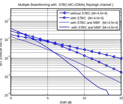
It is clearly seen in Figures 5 and 7 the advantage obtained with multiple beams on the general system compared to STBC without MBF. It can see that when the number of antenna increases the better response is given.
In MBF-CDMA case For M = 3 and N = 4 the BER is at
0.4x10⁻³ approximately, by cons the low BER is at 0.3x10⁻⁴ for
M = 4 and N = 4.
In MC-CDMA case For M = 3 and N = 4 the BER is at 0.5x10⁻⁴
approximately, by cons the low BER is at 10-5 and an SNR at
13 dB only for M = 4 and N = 4.
The simulation of Figures 6 and 8 shows the advantage largely contributed by multiple beamforming and VBLAST detector from ZF or MMSE, the bit error rate is at 10-5 for an SNR of
14dB in the CDMA case and the BER is at 10-5 at 11 dB in the
MC-CDMA case . In addition, the number of antennas increases the better result. Compare also the case of STBC it was a low BER and low SNR for the V-BLAST case.
It can see in this work the advantage largely provided by the MBF-MC-CDMA system over the MBF-CDMA system in frequency selective channel.
6. CONCLUSION
The objective of this research was combined multi-access with MIMO channels composed by antennas array at trasmitter and
antenna arrays at receiver with adaptive multiplebeamforming
(multi-beam) at receiver. optimization criterion chosen was the Minimum mean Square Error (MMSE) algorithm for its ease of implementation using a reference sequence for each transmit antenna i=1,...,M in the detection of transmitted symbols for MBF-STBC-CDMA,MBF-V-BLAST-CDMA,MBF-STBC-MC-CDMA and MBF-V-BLAST-MBF-STBC-CDMA,MBF-V-BLAST-CDMA,MBF-STBC-MC-CDMA systems .
[image:6.595.65.273.532.772.2]into sub channel information, each of them being transmitted by
its respective antenna i after being modulated, provides a better
performance compared to the STBC coding studied and
[image:7.595.317.521.78.241.2]therefore greater transmission capacity .
Fig 5: Performance of STBC-MBF-MIMO-CDMA
[image:7.595.66.266.140.306.2]Fig 6: Performance of VBLAST-MBF-MIMO-CDMA
[image:7.595.67.268.353.520.2]Fig 7: performance of STBC-MBF-MIMO-MC-CDMA
Fig 8: Performance of VBLAST-MBF-MIMO-MC-CDMA
Acronyms
BF Beamformer
BICM Bit-Interleaved Coded Modulation
MBF Multi-Beamformer
7. REFERENCES
[1] G. J. Foschini and M. J. Gans.‟‟On limits of wireless communications in a fading environment when using multiple antennas‟‟. Wireless Personal Communications, march 1998.
[2] S. Hera and R. Prasad “Overview of multicarrier CDMA,” IEEE Communications Magazine, Vol. 35, No. 12, pp. 126-133, Dec.1997.
[3] E. O. J. Eriksson and V. Koivunen, “Essential statistics and tools for complex random variables,” IEEE Transactions on signal processing, vol. 58, no. 10, pp. 5400–5408, October 2010.
[4] A. J. Paulraj, D. A. Gore, R. U. Nabar et H. Bolcskei, „‟ An overview of MIMO communications a key to gigabit wireless‟‟ Proceedings of the IEEE, vol. 2, no2, pages 198–218, f´evrier 2004.
[5] Lindner J. and Pietsch C,“The spatial dimension in the case of MC-CDMA,” European Transactions on Telecommunica- tions (ETT), vol.13, pp. 431–438, Sept./Oct. 2002.
[6] V. Limpakuntorn and R. Suleesathira, “MIMO Adaptive Beamforming for MC-CDMA System,” 9th International Conference on Advanced Communication Technology, pp. 2217-2221, Feb. 2007.
[7] Nevio Benvenuto, Giovanni Cherubini„‟Algorithms for Communications Systems and their Applications‟‟ 2002 John Wiley & Sons Ltd.
[8] Joseph C.Liberti, Jr. Theodore S.Rappaport„‟ Smart antennas for wireless communications‟‟ Prentice Hall PTR.
[9] B. Vucetic and J. Yuan, Space-Time Coding, Wiley, 2003.
0 5 10 15
10-5 10-4 10-3 10-2 10-1
SNR dB
B
it
e
rr
o
r
R
a
te
Multiple Beamforming with STBC-CDMA(Rayleigh channel)
without STBC (M=4,N=4) with STBC (M=4,N=4)
STBC with MBF at receiver(M=3,N=4) STBC with MBF at receiver (M=4,N=4)
0 5 10 15
10-5 10-4 10-3 10-2 10-1
SNR dB
B
it
E
rr
o
r
R
a
te
Multiple Beamforming with VBLAST-CDMA(Rayleigh channel)
VBLAST without MBF(M=3,N=4) VBLAST without MBF(M=4,N=4) VBLAST with MBF at receiver (M=3,N=4) VBLAST with MBF at receiver (M=4,N=4)
0 5 10 15
10-5 10-4 10-3 10-2 10-1
SNR dB
B
IT
E
R
R
O
R
R
A
T
E
Multiple Beamforming with STBC-MC-CDMA( Rayleigh channel )
without STBC (M=4,N=4) with STBC (M=4,N=4) with STBC and MBF (M=3,N=4) with STBC and MBF (M=4,N=4)
0 5 10 15
10-5 10-4 10-3 10-2 10-1
SNR dB
B
IT
E
R
R
O
R
R
A
T
E
Multiple Beamforming with VBLAST-MC-CDMA( Rayleigh channel )
[image:7.595.66.266.544.713.2]