Industrial Feedback cum Control System
through CAN Protocol
Jaikaran Singh
Assoc. Professor, ECE Shri Satya Sai Institute of
Science & Technology Sehore (M.P)
Mukesh Tiwari
Assoc. Professor, ECE Shri Satya Sai Institute of
Science & Technology Sehore (M.P)
Manish Shrivastava
M. Tech Scholar (VLSI) Shri Satya Sai Institute of
Science & Technology Sehore (M.P)
ABSTRACT
Industrial automation is a sector having vast possibilities for major improvements. The system described in this paper consists of a console master computer (CMC) which will monitor various physical nodes usually found in a large industry. The proposed work analyzes the capability of CAN networking which includes data traffic management. The CMC is designed using MATLAB 7.12; the CAN networking is supported using the Vehicular Network Toolbox. The proposed system using CAN has the advantages of being simple in its design which contributes to the overall low cost. The novelty of the work lies in the low cost approach, and fails safe methodology of CAN communication. The proposed system is capable of sending and receiving signals with the additional benefit of feedback mechanism .The proposed work is implementable in any industry with the cost advantage of CAN interface. The proposed work can be used as a cheaper and robust alternative to native technologies like PLC (Programmable Logic Controller). Moreover, the CAN network system is immune from the electrical interferences.
General Terms
Industrial Feedback, Control System, CAN Protocol
Keywords
Graphical User Interface (GUI), Control Area Network (CAN), Industrial Automation, MATLAB, Vehicular Network Toolbox (VNT).
1.
INTRODUCTION
In the field of industrial automation, the requirements are very tight and security is prime concern. In addition to tightly constrained performance and security, the overall cost for automation must not interfere with the very basic business objective i.e. profit. With the advancement in technology, several new methods [1] are evolving in the automation sector. Some most popular of them are LAN (Local Area Networking) [2], PLC [3] (Power line
communication), ZigBee[4][5] , CAN (Control Area Network) etc.
Our work focuses on developing a graphical user interface (GUI) in MATLAB, which will simulate and monitor several
different physical parameters and also the GUI will take appropriate action with or without human intervention. For the rest of the paper we will refer GUI as console master computer (CMC), since it is acting as a master CAN node as well as several slave nodes.
2.
CAN OVERVIEW
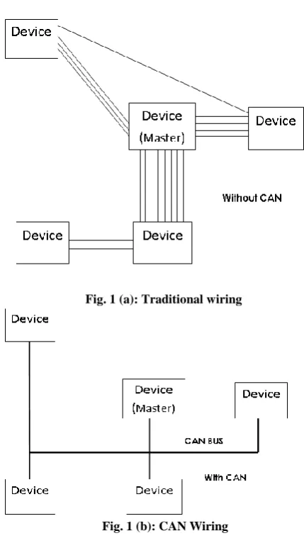
Controller Area Network or so-called CAN is a serial bus that utilizes broadcast method to transmit messages across all CAN nodes [6]. It uses a serial control protocol which provides reliable, efficient and economic link between devices to support the distributed real time applications by using a bitwise deterministic collision-resolution mechanism. It was originally developed in the 1980s by Robert Bosch as an alternative data communications for interconnecting the control components in automotive vehicles. Prior to CAN technology, all manufacturers used to connect devices within vehicles using point to point wiring systems. Wiring started to become more complex, bulky, heavy and expensive as more electronics and controllers are deployed in a vehicle. This problem can be seen in Figure 1(a), where the abundance of wiring is required which makes the whole circuit even more complicated. CAN system can solve this problem by utilizing a twisted pair cable to communicate with each other as shown in Figure 1(b). Initially, it was designed to allow the microcontrollers and devices to communicate with each other within a vehicle without a host computer. It has been fast gaining wide appreciation with further applied in various automation industrial including military, aviation, electronics, factories and many others due to its high immunity towards electrical interference, and the ability to self diagnose and repair the data errors. Additionally, the low cost, performance and upgradeability to provide tremendous flexibility in the system design add to its many advantages [7].
3.
CAN PROTOCOL
using bit-wise arbitration. It is based on a pre-programmed priority of
Fig. 1 (a): Traditional wiring
Fig. 1 (b): CAN Wiring
each message in the identifier field of a message. This configuration allows the messages to remain intact after the arbitration is completed even if collisions are detected. In order for the arbitration process to be successful, the logic states need to be defined as dominant or recessive. An example of CAN arbitration can be seen in Figure 2 when three nodes are assumed to be transmitting simultaneously.
Fig. 2: CAN Arbitration
When three nodes start transmitting their start of frame(SOF) bits simultaneously, the Nodes 1 and 2 stop transmitting as soon as they transmit bit „1‟ (recessive level) while Node 3 is transmitting bit „0‟ (dominant level). At this instance, Node 3
will continue its transmission when the identifier of bit „0‟ has been transmitted while Nodes 1 and 2 are entering into the receiver mode which indicated in grey color. The CAN protocol is defined with the ISO standard of 11-bit identifier that provides for the signaling rates from 125 kbps to 1 Mbps. This standard is later improved to allow for larger number of bit with the "extended" version of 29-bit identifier. The 11-bit identifier standard provides 211 or 2048 different message identifiers while the extended 29-bit identifier standard provides 229 or 537 million identifiers [9]. The data format of both standards can be seen in Figure 3.
Fig 3(a) Standard CAN Format
Fig 3(b) Extended CAN Format
4.
CONSOLE MASTER COMPUTER
Console Master Computer (CMC) is a GUI built on MATLAB software. CMC performs many functions which include:
a) Fixing the set point
b) Visualizing data for future use. c) Start/Stop Communication d) Enable Data Logger
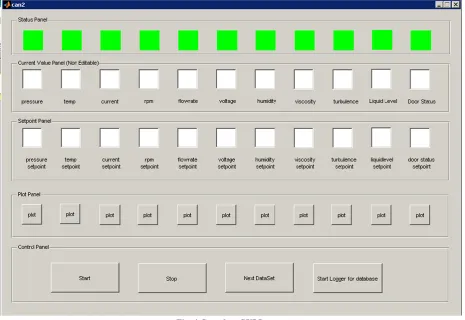
The CMC is based on Vehicular Network Toolbox (VNT) provided by MATLAB. Figure (4) shows the complete GUI. The GUI consists of a status panel which gives the status of current physical node.
Since in an actual setup the various physical nodes will be communication through their own controllers, we have in our simulation, connected them through a loopback mechanism. Two CAN channels are created which are connected in loopback mechanism through VNT; the two channels are sending data through the MATLAB environment. The current values for various nodes are generated through a random number generator. The random values are then transmitted through the specified CAN channels and received by another CAN channel. The CMC then analyses the data and compares it with the set point fixed by the user. If the random value exceeds the set point then the CMC sends OFF command to the physical node through CAN bus.
[image:2.595.51.266.94.474.2] [image:2.595.57.278.559.664.2]
Fig. 4 Complete GUI Layout
[image:3.595.75.526.410.718.2]
Also for visual inspection, the status of physical node changes from green to red indicating that a stop command is given to that particular node. Figure (5) shows the GUI for a particular time instant and the status of the nodes are also visible. The plot utility provides a great facility for the supervisor in an actual industrial setup. With the help of plot button, the supervisor can visually inspect the values coming from the physical nodes and also the set point allocated for that particular node. This allows the supervisor to check for any
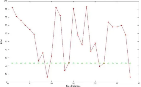
discrepancy that may have crept in at an earlier time. Figure 6 shows the graph displayed by the plot button for the physical node labeled RPM; the graph clearly indicates all the parameters that are required in an industrial setup.
[image:4.595.61.536.182.475.2]The CMC also allows the user to start logger for the whole communication session. With the help of data logger, the VNT will store all the data appearing on the CAN bus into a CAN data bus file. This file can be used for further supervisory analyses.
Fig. 6 Visual status of RPM node at various time instances
5.
COMPARISON
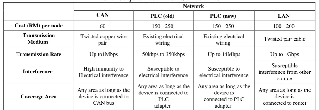
Table 1 shows the comparisons between CAN, PLC and LAN. The price for developing a CAN node is about RM 60 which is lower compared to the PLC and LAN. In terms of transmission medium and rate, CAN uses a twisted copper pair that is capable to make transmission with a rate of 1 Mbps. Although PLC and LAN provide higher transmission rate compared to CAN, they have not been selected because
Table 1 Comparison between CAN, LAN and PLC Network
CAN PLC (old) PLC (new) LAN
Cost (RM) per node 60 150 - 250 150 - 250 100 - 200
Transmission Medium
Twisted copper wire pair
Existing electrical wiring
Existing electrical
wiring Twisted pair cable
Transmission Rate Up to1Mbps 50kbps to 350kbps Up to 14Mbps Up to 1Gbps
Interference High immunity to
Electrical interference Susceptible to electrical interference Susceptible to electrical interference Susceptible interference from other
source
Coverage Area
Any area as long as the device is connected to
CAN bus
Any area as long as the device is connected to
PLC adapter
Any area as long as the device is connected to PLC
adapter
Any area as long as the device is connected to router
6.
CONCLUSION
In this paper, the industrial automation system using CAN as the main communication protocol to control multiple physical nodes has been presented. Based on the simulation results, the proposed system has the capability of controlling physical nodes in industry accurately and effectively with minimal time delay. Moreover, the proposed system has the advantages of being simple in its design which contributed to the overall low cost. Also, by using CAN, the network system is free from electrical interferences as it is immune to it.
7.
REFERENCES
[1] M. G. Golzar, and H. Tajozzakerin, “A New Intelligent Remote Control System for Home Automation and Reduce Energy Consumption,” Fourth Asia International Conference on Mathematical/Analytical Modelling and Computer Simulation (AMS 2010), pp. 174 - 180, 26 – 28 May 2010
[2] D. D. Clark, K. T. Pogran, and D. P. Reed, “An Introduction to LocalArea Networks,” Proceedings of the IEEE, vol. 66, no. 11, pp. 1497 - 1517, 1978.
[3] K. S. Surendran, and H. Leung, “An Analog Spread-Spectrum Interface for Power-Line Data Communication in Home Networking,” IEEE Transactions on Power Delivery, vol. 20, no. 1, pp. 80 - 89, Jan. 2005.
[4] 4. S. Dagtas, G. Pekhteryev, and Z. Sahinoglu, “Multi-Stage Real Time Health Monitoring via ZigBee in Smart Homes,” 21st InternationalConference on Advanced Information Networking and Applications Workshops (AINAW 2007), vol. 2, pp. 782 - 786, 21 - 23 May 2007.
[5] 5. X. H. Li, K. L. Fang, J. G Gu, and L. Zhang, “An Improved ZigBee Routing Strategy for Monitoring System (ICINIS 2008),” First International Conference on Intelligent Networks and Intelligent Systems, pp. 255 - 258, 1 - 3 Nov. 2008.
[6] 6. R. B. GmbH, “CAN Specification,” version 2.0, 1991.
[7] K. Pazul, “Controller Area Network (CAN) Basics,” Microchip Technology Inc, 1999.
[8] S. Corrigan, "Introduction to the Controller Area Network (CAN)," Texas Instrument, Application Report, July 2008.
[9] M. Farsi, K. Ratcliff, and M. Barbosa, “An Overview of Controller Area Network”, Computing & Control Engineering Journal, vol.10, no. 3, pp. 113 - 120, August 1999.