GE-International Journal of Engineering Research
Vol. 3, Issue 11, Nov 2015 IF- 4.007 ISSN: (2321-1717) © Associated Asia Research Foundation (AARF) PublicationWebsite: www.aarf.asiaEmail : [email protected] , [email protected]
THEORITICAL AND FINITE ELEMENT ANALYSIS OF T-JOINT IN ARC
WELDING PROCESS
Arunkumar.A1, Vijayashankar.R2,
1
PG scholar, Department of Mechanical engineering,
KIT-Kalaignarkarunanidhi Institute Of Technology, Coimbatore.
2
Assistant Professor, Department of Mechanical engineering,
KIT-Kalaignarkarunanidhi Institute Of Technology, Coimbatore.
ABSTRACT
Welding is a process used to join two or more pieces of similar or dissimilar metals by
creating a strong metallurgical bond between them by heating or pressure or both. Arc welded
structures are widely used in automobiles, constructions & power plants. As the main cause of
weldment failure is design defect and overload, hence it is necessary to analyze the maximum
stresses in the weldment. This work deals with optimizing the fillet angle and gap between the
parent material of arc welded T joint with plain carbon steel and copper(Cu) material. Here
finite element analysis (ANSYS14.5) which is carried out on welded T-joint under tensile load to
determine the von-misses stress in the weldment. The stress distribution along weld size & throat
thickness is evaluated and also compared with the results from the analysis. Further T-joint weld
is analyzed under static tensile load condition by varying the gap between parent plates with
chamfer at weldment edges.
KEYWORDS-Arc Welded Structures, Finite Element Analysis, T-joint weld, Weldment,
1. INTRODUCTION
The American Welding Society [AWS] defines welding process as “Welding is a
mechanical machining process used to join the two or more metal pieces, which may be similar
or dissimilar creating a strong metallurgical bond between them by heating or pressure or both”.
It is distinguished from other forms of mechanical connections, such as riveting or bolting, which
are formed by friction or mechanical interlocking. It is one of the oldest and reliable methods of
joining.
Welding offers air tight and water tight joints thereby it is ideal for oil storage tanks, ships etc.
Welding could be employed for joining metals of different shapes and sizes. Welded structures
are stronger compared to structures made of riveted joints and other permanent joints. A truly
continuous structure is formed by the process of fusing the members together. Generally welded
joints are as strong , thereby placing no restriction on the joints. Stress concentration effect is
also considerably less in a welded connection
Some of the disadvantages of welding are that it requires skilled manpower for welding
as well as inspection. Also, non-destructive evaluation may have to be carried out to detect
defects in welds. Welding in the field may be difficult due to the location or environment.
Welded joints are highly prone to cracking under fatigue loading large residual stresses and
distortions are developed in welded connections.
2. PROBLEM IDENTIFICATION
Arc welding is a metal joining process used in automobiles and construction applications
etc. In bridge construction T- joints and butt joints are mostly used. As the main cause of
weldment failure of T-joint is defect in design & overload, hence it is necessary to analyze the
maximum stresses and breaking stress in the T-welded joint. Finite element analysis (ANSYS)
used to predict this causes and to gives a applicable accurate weldment.
3. SPECIFICATION OF THE PROBLEM
For the FE analysis on the weldment of T joint two plates of uniform dimensions of
(100 mm X 50mm X 5mm) thick are welded with weld size of 4 mm\with the gap between them
to take into account the positional error which occurs during welding or manufacturing. The
material taken as a copper(Cu). The gap between parent plates is varied from 0.2 mm to 1.0 mm
in the step of 0.2 mm to take into account the positional error. It is also felt necessary totake into
account the effect of chamfer normally provided on vertical plate and hence chamfer angle of
30º, 45º & 60º are considered during the analysis. In this work static analysis, determination of
breaking stress of weldment is carried out.
4. OBJECTIVE
Objective of this research work is to find out of the applicable accuracy fillet angle and
gap between parent material, weld size, changing the gap between parent plates to predict the
static & fatigue failure for automobile and construction application.
The design model is created by using SOLID WORKS software package as per the given
dimensions, analyzed in ANSYS and the problems have been also solved theoretically. The
experimental investigation of the same will be carried out in future.
5. MATERIAL SELECTION
Plain carbon steels are taken as to be a weld material. Plain carbon steel is important
classes of engineering materials that have been used widely in structural and automobile
applications. These are the one class of carbon steels. Carbon steels are alloys of iron and carbon
in which carbon does not exceed 1%, manganese does not exceed 1.65%, and copper and silicon
each do not exceed 0.6%. Plain carbon steels with 0.15 to 0.20% carbon have excellent
weldability.
They seldom require anything beyond standard welding procedures, and these can be
welded with all types of mild steel electrode. Copper is alloy taken as a filler material. Copper
has a face centered cubic crystal structure. They have good formability and malleability. They
have welding factors of high electrical and thermal conductivities and certain high copper alloys
have marked effect of weldability.
Copper have high thermal conductivities, so welding heat is quickly conducted into base.
This may cause lack of fusion in weldment. Preheating of these alloys will reduce welding heat
requirements for good fusion. For this reason plain carbon steel and copper is selected as base
6. NUMERICAL CALCULATION
[image:4.612.151.466.114.333.2]6.1 Weldment under Tensile Load
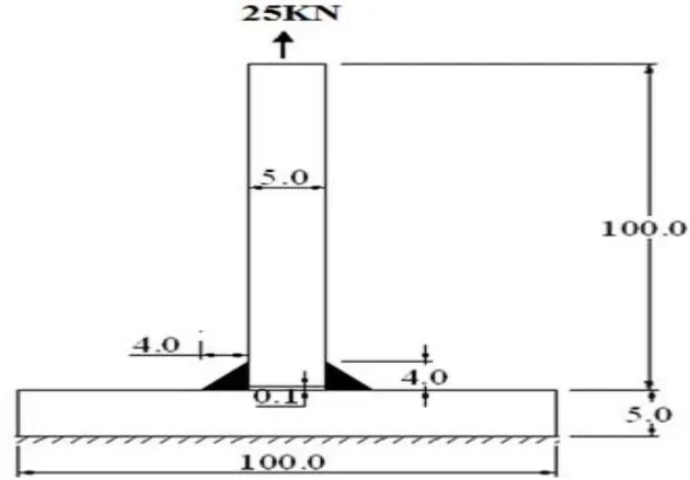
Fig. 6.1 Arc weld of T-joint under tensile load
The above fig 6.1 represents the T-joint fillet weld sections with dimensions
(100x50x5mm) with fillet angle 45º. Here 25 KN tensile load acting upward on the top of the
section. The base weld material is plain carbon steel and filler material is copper (Cu).
T-joint fillet weld dimensions are specified are as follows.
F -Tensile load on vertical plate (N) = 25KN
w -Leg length of weld (mm) = 4.0 mm
h -Throat of fillet weld (mm) = w X [cos45º ]
l -Length of weld or size of weld (mm) = 50mm
b- breath of the weld(mm) = 50mm
𝑙𝑇- length of top load section = 5mm
𝑏𝑇-breath of top load section = 50mm
𝑙𝑡 -throat length = 4mm
𝑡 - throat thickness = 1mm
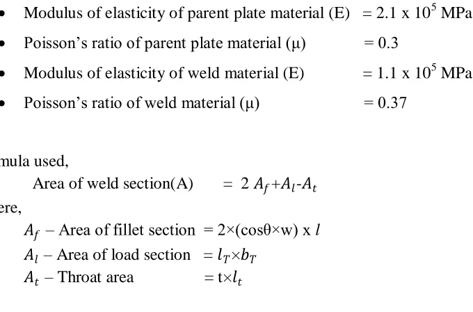
The material properties are specified are as follows,
Modulus of elasticity of parent plate material (E) = 2.1 x 10⁵ MPa
Poisson’s ratio of parent plate material (μ) = 0.3
Modulus of elasticity of weld material (E) = 1.1 x 10⁵ MPa
Poisson’s ratio of weld material (μ) = 0.37
Formula used,
Area of weld section(A) = 2 𝐴𝑓+𝐴𝑙-𝐴𝑡 Where,
𝐴𝑓 – Area of fillet section = 2×(cosθ×w) x l
𝐴𝑙 – Area of load section = 𝑙𝑇×𝑏𝑇 𝐴𝑡 – Throat area = t×𝑙𝑡
Therefore,
Breaking stress = (Breaking Load /Throat Area) X Stress Concentration Factor
=𝐴𝑃
𝑡×k
Stress concentration factor (k) parent material given by Karl Heinz Frank is the range of 3.5 to 4.
7. NUMERICAL RESULTS
7.1 Tabulated Breaking Stress Values from Numerical Calculation
The Maximum breaking stresses present in T-joint weldment at the throat thickness with
[image:5.612.91.431.49.273.2]gap variation and the variation of Maximum breaking stress with respect to gap is also shown in
Table. 7.1. Where 30º, 45º & 60º chamfer is provided on the vertical plate by varying the gap of
Gap between parent
plates (mm)
Breaking stress for 25KN(Mpa)
30º 45º 60º
0.2 130.07 187.96 222.62
0.4 130.20 188.25 223.01
0.6 130.34 188.50 223.41
0.8 130.48 188.68 223.81
1.0 130.60 189.90 224.60
Table7.1 Numerical results for breaking stress with different angle and gap between parent materials
8. FINITE ELEMENT ANALYSIS
Finite Element Analysis (FEA) is a computer-based numerical technique for
calculating the strength and behaviour of engineering structures. It can be used to
calculate deflection, stress, vibration, buckling behaviour and many other phenomena.
It also can be used to analyse either small or large-scale deflection under loading or
applied displacement. It uses a numerical technique called the finite element method
(FEM). In finite element method, the actual continuum is represented by the finite
elements
In this project finite element analysis is carried out using the FEA software
ANSYS. The primary unknowns in this structural analysis are displacements and other
quantities, such as strains, stresses, and reaction forces, are then derived from the nodal
displacements.
8.1 Design Model
1. Boundary Conditions
The finite element model of welded T-joint is shown in Fig.8.1 Bottom end is fixed and
Fig.8.1 T-joint of design model
Above this Fig8.1 represents the design model of T-joint welded section with
(100×50×5mm) and the fillet angle 45 degree. This design model element is created by using
SOLID WORKS software
2 Element Meshing
Meshing is the discretization of the element into number of small components. It used to
increase accuracy result of the element. For this analysis course mesh type is used. This below
Fig.8.2 represents the meshed element of T- joint weld section by using ANSYS 14.5 workbench
Fig.8.2 Meshed Element
3 Remote Force
This below Fig8.3 represents the tensile load 25KN applied on top of plate and bottom
surface of the plate fixed by using ANSYS workbench software.
8.2 Equivalent (Von-Misses) Stress
Von misses stress is widely used by designers to check whether their design will withstand a
given load condition.
Von misses stress is considered to be a safe haven for design engineers, if the maximum
value of von misses stress induced in the material is more than strength of the material. Its work
well for most cases, especially when the material is ductile in nature.
1. For 25KN load, θ = 45º and 1 mm gap
Fig8.4 Equivalent von-misses stress for 45º degree and 1mm gap
The above Fig.8.4 represents the equivalent von misses stress value is 205.09Mpa for 45º
2. 25KN load, θ = 60º and 1mm gap
Fig8.5 Equivalent von-misses stress for 60º degree and 1mm gap
3. 25KN load, θ = 30º and 1mm gap
Fig8.6 Equivalent von-misses stress for 30º and 1mm gap
The above two figures 8.5 and 8.6 represents the equivalent von misses stress value is 252.7 Mpa
9. ANALYSIS RESULT
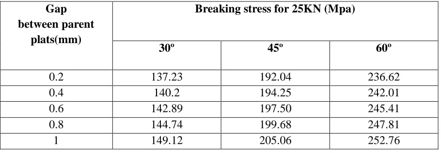
FE analysis is also carried out by considering the chamfer on vertical plate. The
Maximum von-misses stresses present in T-joint weldment at the throat thickness with gap
[image:11.612.80.535.173.331.2]variation and the variation of Maximum breaking stress with respect to gap is also shown in
Table 9.1. Where 30º, 45º & 60º chamfer is provided on the vertical plate by varying the gap of
0.2 to 1.0 mm in the steps of 0.2 mm.
Gap between parent
plats(mm)
Breaking stress for 25KN (Mpa)
30º 45º 60º
0.2 137.23 192.04 236.62
0.4 140.2 194.25 242.01
0.6 142.89 197.50 245.41
0.8 144.74 199.68 247.81
1 149.12 205.06 252.76
Table.9.1 Analysis results for Von misses stress with different angle and gap
10. EVALUATION
From the analytical calculations and finite element results the equivalent von misses stress
75% approximately equal. The FE analysis of T-welded joint for the same geometry revealed the
maximum Von-misses stress of 252.76 Mpa is approximately equal to numerical maximum
breaking strength of 224.2Mpa.
11. CONCLUSION
The finite element analysis is used in this work to evaluate the deformation breaking
stress of weld T- joint. Static stress analysis performed on the weldment under tensile load
revealed the maximum Von-misses stress with respect to the gap between parent plates. The
design and analysis of welded T-joint has been done successfully. The theoretical results are
compared with analysis (ANSYS work bench 14.5) result and both are acceptable.
Static stress analysis performed on the weldment under axial tensile load revealed the
joint for the same geometry revealed the maximum Von-misses stress of 252.76 Mpa for 60º
degree and 1mm gap, it’s approximately equal to numerical maximum breaking strength of 224.2
Mpa.
The gap between parent plates increased from 0.2 mm to 1.0 mm, the maximum
Von-misses stresses decreases from 252.34MPa to 236.22MPa.
12. SCOPE AND FUTURE WORK
From the theoritical and finite element analysis results are approximately equal. The
design and analysis of welded T-joint has been done successfully for T-joint fillet weld under
tensile load with angle and gap between parent materials.
In future same analysis is carried out for experimental investigation will do for later with
plain carbon steel and copper under tensile conditions.
13. REFERENCES
[1] Dean Deng, Wei Liang, Hidekazu Murakawa(2007) “Determination of Welding deformation in fillet-welded joint by means of numerical simulation and comparison with experimental measurements”. Journal of Materials Processing Technolog , 183:219-225.
[2] Tso-Liang Teng, Chin-Ping Fung(2001) “Analysis of residual stresses and distortions in T-joint fillet welds” International journal of Pressure Vessels and Piping,78:523-538.
[3] Mohd Shahar Sulaiman, Chan Yin Chau(2011) “Simulation and experimental study on distortion of butt and T-joints using WELD PLANNER, Journal of Mechanical Science and Technology ,25:2641-2646.
[4] M.N.Buradkar, Dr. D.V. Bhope, S. D. Khamankar(2013), “Experimental & photo elastic analysis of arc welded lap-joint” Kotiya, et al, International Journal of Advanced Engineering Research and Studies,2247:112-115.
[5] Kim JR Rasmussen(2002), “Strength of Butt Welded Connections between Equal-width Rectangular Hollow Sections”Research Report No R817.
[6] Shahram Sarkani, George Michaelov(2000) “An efficient approach for computing residual stresses in welded joints” Finite Elements in Analysis and Design. School of
Engineering and Applied Science, The George Washington University, Washington, DC 20052,
USA, 35:247-268.
[8] N.B. Mostafa, M.N. Khajavi(2006), “Optimisation of welding parameters for weld penetration in FCAW” journal of Achievements in Materials and Manufacturing Engineering. 16:132-137.
[9] A. Unt, E. Lappalainen, A. Salminen(2013), “Autogeneous laser and hybrid laser arc welding of T-joint low alloy steel with fiber laser systems” Lasers in Manufacturing Conference, 41:141-143.
[10] M. Islam, A. Buijk(2014) “Simulation-based numerical optimization of arc welding process for reduced distortion in welded structures. journal homepage: www.elsevier.com/locate/finel,84:54-64.
[11] Jichao SHEN, Zhen CHEN(2014), “Welding Simulation of Fillet-welded Joint Using Shell Elements with Section Integration” Journal of Materials Processing Technology, 34:01-47.
[12] Hyeong soon moon, suck joo- na(1997), “Optimum design based on mathematical model and neural network to predict weld parameter for fillet joints “journal of manufacturing system,16:13-22.
[13] M. E. Scholar(2013), “A Review on Parametric optimization of MIG Welding for Medium Carbon Steel using FEA-DOE Hybrid Modeling” IJSRD - International Journal for Scientific Research & Developmen,30:1843-1846.
[14] Matt I. Dawson(2008) “Modeling and Analysis of Welding Processes in Abaqus using the Virtual Fabrication Technology (VFT) Analysis Software developed by Battelle and Caterpillar Inc” .Abaqus Users’ Conference.20:1-14.