Power Quality Improvement & Harmonic Elimination using Shunt
Active Power Filter
Ganesh Chaudhari
1Prabodh Khampariya
21,2
SSSUTMS Sehore, India
Abstract— In this paper, a three-stage dynamic power channel is introduced to enhance the power nature of a framework which supplies a three-stage non-straight load. For this reason, a three-stage voltage source inverter connect with a dc transport capacitor is utilized as a dynamic power channel. Another control procedure is proposed which depends on two well-known techniques: synchronous d-q reference outline strategy and synchronous current location strategy which have their own particular points of interest and drawbacks. The proposed control procedure depends on both of two specified systems keeping in mind the end goal to get a decent precision and also settling the present reaction to consistent state esteem rapidly. A Hysteresis based transporter less PWM current control over the charge streams of the dynamic power channel is utilized to infer the gating signals. PC reproduction comes about are given to confirm the adequacy of the proposed strategy. Issues caused by control quality have extraordinary antagonistic financial effect on the utilities and clients. Current sounds are a standout amongst the most widely recognized power quality issues and are generally settled by the utilization of shunt uninvolved or dynamic channels. In this paper, another control configuration utilizing counterfeit neural systems is proposed to make the traditional shunt dynamic channel versatile. The proposed versatile shunt dynamic channel can make up for consonant streams, control factor and nonlinear load unbalance. A self-charging method is additionally proposed to direct the dc capacitor voltage at the coveted level with the utilization of a PI controller. The plan idea of the versatile shunt dynamic channel is confirmed through re-enactment ponders and the outcomes got are talked about.
Key words: Shunt Active Power Filter, Power Quality, Harmonic Elimination
I. INTRODUCTION
The power quality term is utilized as a part of energy framework to portray the deviation of voltage or/and current from its optimal waveform. In a perfect world, voltage and current in control framework are to be a sinusoidal one. The advancements of energy electronic gadgets for different applications have brought about power quality issues. Because of the wide use of energy hardware gadgets sinusoidal waveforms are not found in the present power frameworks. Power hardware gear draws non-direct present or contorted current from the framework. As the present contortion is directed through transmission line impedance, it makes a mutilated voltage drop over the transmission line impedance. This causes voltage bending in different parts of the power framework. Voltage twisting because of current music has turned into a noteworthy issue for the utilities at circulation levels. Line misfortunes and misfortunes in electrical supplies associated in the transmission framework are expanded because of the high symphonious current moving through framework. To transmit a similar measure of energy with symphonious current higher evaluations of
the utilization of transformers. Delta-wye transformers decrease certain music, especially zero succession music [2]. Crisscross transformers can likewise be utilized to decrease zero arrangement music, however without changing the framework write amongst delta and wye [5, 6]. These strategies won't give attractive outcomes under factor stack conditions. To defeat these issues dynamic channels are presented. Adaptable infusion of current or voltage is conceivable with dynamic channels so it is conceivable to accomplish the coveted estimation of supply current or voltage [4]. Dynamic channels are named arrangement and shunt dynamic channels. Dynamic channel which infuse voltage in arrangement with the transmission line for making supply voltage at a coveted esteem is called as arrangement dynamic channel. Dynamic channel which infuses receptive and sounds control into framework so the current can be made in stage with the voltage and sinusoidal fit as a fiddle is called as shunt dynamic channel (SAF). A schematics of a shunt dynamic channel associated with control framework is appeared in Fig.1.2. A shunt APF comprises of a controllable voltage or current source inverter. The voltage source inverter (VSI) based shunt APF is the most normally utilized.
II. LITERATURE SURVEY
Luis Saenz [1] in his paper portray The control and estimating of dynamic electrical cable conditioners (APLC) hardware depend on the speculation that NLLs carry on as "present sources" whose swell might be wiped out by infusing a counter-stage set of consonant streams. In any case, the interior impedance of the appropriation arrange impacts the genuine conduct of NLLs, with the goal that when the APLC controller tries to scratch off symphonious streams at a worldwide level, sounds produced by the NLLs increment. The impact of including or evacuating NLLs the aggregate current utilization is dissected. Current mutilation per unit of energy appears to diminish with expanding NLL control. Correspondingly, an evident increment of current bending per unit of energy is identified with lessening current twisting, for instance, by utilizing shunt channels. Cristian Lascu [2] in his paper portray the four current control structures for particular consonant pay in dynamic power channels. All controllers under investigation play out the consonant pay by utilizing varieties of full controllers, one for the essential and one for every symphonious of enthusiasm, so as to accomplish zero stage move and solidarity pick up in the shut circle exchange work for chosen sounds. The particular symphonious current control is an alluring answer for shunt APF, since each chose consonant is recognized and independently controlled in its own reference outline. The strategy is costly as far as ongoing computations, however it gives great relief execution because of an exact control of every symphonious current.
Emad Ezzat Ahmed [3] in his paper portray the lessening and assorted variety impacts in symphonious mutilation appraisal for frameworks with circulated consonant sources. In this paper is to present a strategy that can consider the principal factor in (deterministic) symphonious evaluation. A common case that can be broke down by the proposed technique is the business electric frameworks. Such frameworks have numerous appropriated symphonious delivering office gadgets. Fundamental focal
point of this paper is a solitary stage symphonious source utilizes a capacitor-sifted diode connect rectifier circuit. Customary symphonious appraisal strategies overlook the lessening and assorted variety impacts. Two kinds of tests were led. The primary examination is to change the supply impedance so an alternate level of symphonious contortion is made at the terminal of a test PC regarding an exchanged mode control supply. The second examination is to change the quantity of other symphonious sources in the framework, making distinctive measure of foundation voltage twists.
Johan H. R. Enslin [4] in his paper portray the Power quality issues related with conveyed control (DP) inverters, executed in substantial numbers on to a similar circulation arrange, paper is to investigate the watched marvels of consonant impedance of extensive populaces of these inverters and to look at the system association of various inverter topologies and control choices. These power quality wonders are researched by utilizing broad lab tests, and PC displaying of various inverter topologies. An entire system recreation think about on a current private system with vast entrance of PVs, is incorporated.
Ahmed Faheem Zobaa [5] in his paper depict the strategy is displayed for finding the ideal settled inductance– capacitance mix to limit voltage symphonious contortion at a heap transport where it is wanted to keep up the dislodging power factor at a coveted level obliging the compensator esteems, which would make reverberation conditions, and the makers' standard qualities for control shunt capacitors. A correlation investigation of utilizing the limitation, holding either the removal control factor or the power factor at a coveted esteem, is finished. At long last, the commitment of the recently created technique is exhibited in six illustrations taken from existing distributions. In his paper displays a technique for limiting the VTHD at the heap transport where it is wanted to keep up the dPF at a coveted level by utilizing Penalty Function strategy as a device of enhancement. An ideal settled LC compensator will be chosen that will limit the normal estimation of VTHD for a predetermined scope of source consonant and impedance esteems, while obliging the compensator esteems which would make thunderous conditions. One issue to be tended to is whether the qualities acquired from hypothetical advancement arrangement can be gotten from standard produced esteems. Contingent upon the voltage, makers have discrete capacitors accessible. In the exhibited technique, maker's standard qualities for shunt capacitor are contemplated. The standard qualities are considered as requirement as in picked capacitor ought to be one of these qualities.
III. DESIGNING & MODELING OF PROBLEM
A. Case 1: Non-Linear Load
Fig. 4.1: Mat Lab Model of Shunt Active Filter with its Control Circuit
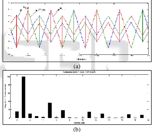
The waveforms of source voltage (vsa,vsb,vsc)
and the load currents (
la
i ,
lb
i ,
lc
i ) are given in Fig.4.2. To
make power factor unity the current should be sinusoidal and in phase with the supply voltage. It is clear that the fundamental component of current is in phase with the voltage. The power factor is less than one due to distortion in current waveform. By compensating for the distortion power, we can improve the power factor of the supply terminal near to unity.
(a)
Table 4.1, shows the simulation results of case 1 before compensation. Table shows that power factor is 0.95. Harmonics spectrum of load current is shown in Fig.4.3 in which 5th, 7th, 11th, 13th number of harmonics are present. The measured THD in load current is 30.17%. The power factor can be improved by shaping the supply current to a sinusoidal one using shunt active filter. Fig.4.4 shows voltage and current waveform in phase a.
Active power PL (kW)
Reactive Power QL (kVAR)
Load Voltage Vlrms (V)
Load Current Ilrms (A)
Power Factor P.F.S
[image:3.595.45.288.67.214.2]58.32 0 400 88.18 0.95
Table 4.1: Simulation Results of Case 1 before Compensation
Fig.4.3 Harmonics Spectrum of Load Currentila
Fig. 4.4: Waveforms of vsa &
la
i before Compensation
Load current is detected and the reference repaying current is acquired utilizing d-q hypothesis. Remunerating current is appeared in Fig. 4.5(a). PLL square is utilized to synchronize the repaying current with the supply voltage. Fig. 4.5(b) demonstrates the sounds range of remunerating current. It is obvious from the waveforms in Fig.4.2 that through the voltage is sinusoidal, current is non-sinusoidal as a result of non-straight load associated with the supply. It is obvious from the music range that repaying current comprises of all sounds part display in the heap current. Subsequently just basic segment of current will be available in the supply current after pay.
(a)
(b)
Fig. 4.5 (a): Waveform of compensating current i*cabc (b)
Harmonics spectrum for compensating current of phase 'a'. Hysteresis control technique is used for generation of pulses to the inverter switches. To implement hysteresis control actual inverter output current is sensed and compared with
reference (i*cabc ). The hysteresis band of 0.5 is considered.
[image:3.595.305.549.335.547.2]The supply current isabc after compensation is shown in
Fig.4.6.
Fig. 4.6 Waveform of isabc after compensation. Non-linear load
Continuous
powergui
A
B
C +
-ABC ABC vsabc
ilabc Ic*abc Reference current generation
g1 g2 g3 g4 g5 g6 A B C
Inverter Ic*abc
Icabc g1 g2 g3 g4 g5 g6 Hysterisis contol
Vabc Iabc A
B C a b c
V-I 2
Vabc IabcA
B
C a b c Vabc
Iabc A
B
C a b c
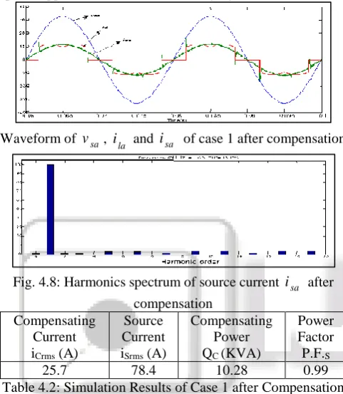
[image:3.595.300.548.554.762.2] [image:3.595.46.286.555.741.2]It can be seen that source current is sinusoidal and in stage with supply voltage. Fig.4.7 demonstrates the source voltage, stack current and source current after pay. Music range of source current is appeared in Fig.4.8 in which just basic part is available. From the reenactment comes about given in Table 4.2, we can see control factor of the supply side is expanded from 0.95 to 0.99 and the rms estimation of the supply current is lessened from 88.18 to 78.4Amp. Additionally present THD is lessened from 30.76 to 13.17%. Through the current is sinusoidal THD is more which is because of the spikes display in the waveform. In this manner spike happens because of the exchanging of diodes.
[image:4.595.307.550.120.319.2]Waveform of vsa, ila and isa of case 1 after compensation
Fig. 4.8: Harmonics spectrum of source current isa after
compensation Compensating
Current iCrms (A)
Source Current iSrms (A)
Compensating Power QC (KVA)
Power Factor P.F.S
25.7 78.4 10.28 0.99
Table 4.2: Simulation Results of Case 1 after Compensation Reactive power from the supply will be zero after compensation. The distortion power consumed by the load is supplied by the shunt active filter and the rms value of the compensator current is found to be 25.7 Amp. The VA rating of the inverter is 10.28 kVA.
B. Case 2:- Combination of Linear & Non-Linear Load
To confirm the execution of shunt dynamic channel under mix of direct and non-straight load an inductor is associated in parallel with the rectifier stack in the event that 1. In the wake of associating straight and non-direct load to framework current turn into a non-sinusoidal and slacking. Fig.4.9 demonstrates the waveforms of source voltage and source current of case 2 preceding remuneration.
(b)
Fig.4.9 (b) Waveforms ofilabc .
Waveforms of supply voltage and load current for stage is appeared in Fig.4.10. . It is seen from the waveform that notwithstanding sounds the heap current is slacking the voltage because of inductive load. Table 4.3 demonstrates the aftereffects of recreation of case 2 preceding remuneration
Fig. 4.10: Waveforms of
v
sa andla
i before Compensation
Active Power PL (kW)
Reactive Power
QL (kVAR)
Load Voltage
Varmus (V)
Load Current
Alarms (A)
Power Factor P.F.S
72.54 36.45 400 120.1 0.8717
Table 4.3 Simulation Results of Case 2 before Compensation
[image:4.595.45.286.205.482.2]Table indicates reactive power is 36.45 car and PFS is low as 0.87 which is due to reactive power as well as harmonics power. Harmonics spectrum of load current is shown in Fig. 4.11. It shows that harmonics order 5, 7, 11, 13 etc. are present.
Fig. 4.11: Harmonics spectrum of load currentila
Compensating current i*cabc is shown in Fig.4.12.
[image:4.595.306.551.363.465.2]Fig.4.13 shows that the waveform of source current after compensation which is sinusoidal as well as in phase with the voltage. The power factor of the supply side is improved from 0.8717 to 0.99 which is given in Table 4.4. Results show that the supply current is reduced from 120.1 to 78.7Amp.
[image:4.595.307.548.559.758.2]Fig.4.12 Waveform of Compensating Current i*cabc.
Fig.4.13 Waveform of isabc of Case 2 after Compensation
[image:4.595.54.282.642.752.2]Harmonics spectrum of source current isa after
[image:5.595.52.281.141.309.2] [image:5.595.310.547.371.496.2]compensation for phase 'a' is shown in Fig.4.14. Fig.4.15 shows the source voltage, load current and source current after compensation. It can be seen that source current is sinusoidal and in phase with supply voltage.
Table 4.4 Simulation results of case 2 after compensation Active
Power PS (kW)
Compen sating Current Isrms (A)
Source Current Isrms (A)
Compe nsating Power QC (kVA)
Power Factor P.F.S
54.00 87.3 78.7 34.92 0.99
Fig. 4.14: Harmonics spectrum of source current isa after compensation.
Voltage (V), Current(A)
The advantage of d-q theory is that if the shunt active filter is be used only to compensate for harmonics, the compensating current can be easily calculated. The supply voltage along with it's supply current after compensation is shown in Fig.4.16.
(a)
(b)
Fig.4.16 (a) Waveforms of Supply Voltage and (b) Waveforms of Current when Shunt Active Filter
Compensate only Harmonics
C. Case 3: Non-linear load (RSC=60, XSC=1.2) & (RSC=20,
XSC=1.2)
The NLL accept that these heaps act like settled symphonious current sources or as consonant current sources depending just on the major supply voltage. It is notable that these models prompt an overestimation of sounds created by NLLs in light of the non-thought of the voltage drop at consonant frequencies in the investigation of NLL conduct. Practically speaking, there is a cooperation between symphonious supply voltages and NLL consonant streams because of the power framework impedance, which is related with the constriction marvel and portrayed with the weakening component. As an outcome of such voltage-current consonant communication, the utilization of a dynamic or aloof shunt channel to decrease current swell in a supply arrange alters the symphonious voltages and, in this manner, it affects the NLL consonant streams. All the more decisively, if shunt channels make up for the symphonious streams, voltage mutilation diminishes (i.e., the supply voltage approaches a sinusoidal shape) and NLLs respond by producing more consonant ebbs and flows. Subsequently, the worldwide current swell isn't completely adjusted for. This paper is particularly committed to the investigation of the impact of consonant voltage collaboration on streams created by NLLs when utilizing dynamic channels to diminish the worldwide current mutilation at the purpose of normal coupling (PCC), see Fig.4.17.
Fig. 4.17: Single-line diagram of Distribution power system
IV. CONCLUSION
The estimating and control of Shunt Active Filter depend on the theory that nonlinear load act as "present sources" whose swell might be scratched off by infusing a counter-stage set of consonant streams. The inward impedance of the circulation organize impact the genuine conduct of Nonlinear load, with the goal that when the Shunt Active Filter controller tries to cross out consonant streams at a worldwide level, music created by the NLLs increment.
Parameter Nonlinear Loads % THD
RSC=60, XSC=1.2 m=1 13.39
RSC=60, XSC=1.2 m=3 9.98
RSC=20, XSC=1.2 m=1 10.30
RSC=20, XSC=1.2 m=3 6.04
Table 6: Total Harmonic Distortion (THD)
REFERENCES
[image:5.595.50.286.507.728.2] [image:5.595.333.527.626.701.2]TRANSACTIONS ON POWER DELIVERY, VOL. 27, NO. 3, JULY 2012
[2] Cristian Lascu & Lucian Asiminoaei, Frequency Response Analysis of Current Controllers for Selective Harmonic Compensation in Active Power Filters, IEEE
TRANSACTIONS ON INDUSTRIAL
ELECTRONICS, VOL. 56, NO. 2, FEBRUARY 2009. [3] Emad Ezzat Ahmed, Wilsun Xu, Analyzing Systems
with Distributed Harmonic Sources Including the
Attenuation and Diversity Effects, IEEE
TRANSACTIONS ON POWER DELIVERY, VOL. 20, NO. 4, OCTOBER 2005.
[4] Johan H. R. Enslin and Peter J. M. Heskes, Harmonic Interaction Between a Large Number of Distributed Power Inverters and the Distribution Network, IEEE TRANSACTIONS ON POWER ELECTRONICS, VOL. 19, NO. 6, NOVEMBER 2004.
[5] Ahmed Faheem Zobaa, The Optimal Passive Filters to Minimize Voltage Harmonic Distortion at a Load Bus, IEEE TRANSACTIONS ON POWER DELIVERY, VOL. 20, and NO. 2, APRIL 2005.
[6] F. Corasaniti, M. B. Barbieri, “Comparison of Active Filters Topologies in Medium Voltage Distribution Power Systems”, Power and energy society general meeting –conversion & Delivery of Electrical energy in 21st century,2008 IEEE,20-24 July 2008.
[7] IEEE Recommended Practices and Requirements for Harmonic Control in Electrical Power Systems, IEEE SM 519-1992 (Revision of IEEE SM 519-1981). [8] Asaad Ali Elmoudi, “Evaluation of Power System
Harmonic Effects on Transformers Hot Spot Calculation and Loss of Life Estimation”, Helsinki University of Technology, Power Systems and High Voltage Engineering, September 2005.
[9] Gary W. Chang, Hung-Lu Wang, a Probabilistic Approach for Optimal Passive Harmonic Filter Planning, IEEE TRANSACTIONS ON POWER DELIVERY, VOL. 22, NO. 3, JULY 2007.
[10]Gary W. Chang, Shou-Yung Chu, A New Method of Passive Harmonic Filter Planning for Controlling Voltage Distortion in a Power System, IEEE TRANSACTIONS ON POWER DELIVERY, VOL. 21, NO. 1, JANUARY 2006.
[11]Narain G. Hingorani, Laszlo Gyugyi, Understanding FACTS Concepts and Technology of Flexible AC Transmission Systems”.
[12]Sincy George and Vivek Agarwal “A novel, DSP based algorithem of optimizing the harmonics and reactive power under the non-sinusoidal supply voltage condition”, IEEE Transactions on power delivery, vol. 20, no. 4, October 2005, pp 2526-2534..
[13]W. Edward Reid, “Power quaility issue standared and guidelines”, IEEE Transaction industrial application, vol. 32, pp.625-632, May/June 1996.
[14]Ruben Inzunza, Hirofumi Akagi, “A 6.6 Kv transformerless shunt hybrid active filter for installation on a power system”, IEEE Transactions on power electronics, vol. 20, no. 4, July 2005, pp. 893-899. [15]Victor Fabián Corasaniti, Maria Beatriz Barbieri,
Patricia Liliana Arnera, and María Inés Valla, “Hybrid Active Filter for Reactive and Harmonics Compensation
in a Distribution Network,” IEEE Trans. Ind. Electron. vol. 56, no. 3,March 2009.
[16]Victor Fabian Corasaniti, Maria Beatriz Barbieri, Patricia Liliana Arnera, and María Inés Valla, “Hybrid power filter to enhance power quality in a medium voltage distribution network”, IEEE Trans. Ind. Electron. vol. 56, no. 8, August 2009, pp. 2885-2893. [17]Sunt Srianthumrong, Hirofumi Akagi, “A
Medium-Voltage Transformerless AC/DC Power Conversion System Consisting of a Diode Rectifier and a Shunt
Hybrid Filter,” IEEE TRANSACTIONS ON
INDUSTRY APPLICATIONS, VOL. 39, NO. 3, MAY/JUNE 2003.
[18]Iman Ziari , Ahad Kazemi , Alireza Jalilian, “ Using active power filter based on new cotrol strategy to compensate power quality”, First International Power and Energy Coference PECon 2006. November 28-29, 2006, Putrajaya, Malaysia pp.373-377.
[19]Hirofumi Akagi, Edson Hirokazu Watanabe, Mauricio Aredes, Instantenious power theory and applications to power conditioning, IEEE press, ISNB 978-0-470-10761-4. pp. 1-379.
[20]Vinod Khadkikar, Mukhtiar Singh, Ambrish Chandra, and Bhim Singh”,Impementation of single phase synchronous d-q reference frame controller under distorted voltage condition”, Power Electronics, Drives and Energy Systems (PEDES) & 2010 Power India, 2010 Joint International Conference on Issue Date: 20-23 Dec. 2010. pp. 1 – 6.
[21]G. Jayakrishna, K.S.R.Anjaneyulu, “Fuzzy Logic Control based Three Phase Shunt Active Filter for Voltage Regulation and Harmonic Reduction”, International Journal of Computer Applications (0975 – 8887) Volume 10– No.5, November 2010.
[22]Dahono P.A, “New hysteresis current controller for single-phase bridge inverters” IET journal on Power electronics, vol.2 (2009):pp. 585-594.
[23]SPRS698C –NOVEMBER 2010–REVISED MAY
2012, Texas Instruments.
[24]Paul C. Krause, Oleg Wasynczuk, Analysis of electrical machinery and drive systems, IEEE press, ISNB 978-1-265-2512-6. pp. 1-613.
[25]Ned Mohan, Tore U. Undeland, Power electronics converter applications and Design, Wiley India edition. [26]C. Sankaran, Power Quality, 2002 by CRC Press LLC. [27]Gonzalo Casaravilla, Adriana Salvia, César Briozzo, and
Edson H. Watanabe, Selective Active Filter With Optimum Remote Harmonic Distortion Control, IEEE TRANSACTIONS ON POWER DELIVERY, VOL. 19, NO. 4, OCTOBER 2004.
[28]Mahesh M. Swamy, and Steven L. Rossiter, Harmonic Interaction Between 1500-kVA Supply Transformer and
VFD Load at an Industrial Plant, IEEE