An Adaptive Sliding Surface Slope Adjustment in Sliding
Mode Fuzzy Control Techniques for
Brushless DC Motor Drives
C. Navaneethakkannan
Research Scholar
Department of Electrical and Electronics Engineering
Anna University, Coimbatore.
M. Sudha,
Ph.D Professor & HODDepartment of Electronics and Communication Engineering
Karpagam Institute of Technology, Coimbatore.
ABSTRACT
This paper presents the development and performance analysis of intelligent control techniques such as Sliding Mode controller and Fuzzy logic Controller for Brushless DC (BLDC)motor drives. Today, strong mathematical tools used in new control methodologies to design adaptive nonlinear robust controller with acceptable performance. One of the best nonlinear robust controller which can be used in uncertainty nonlinear systems, are sliding mode controller but pure sliding mode controller has some disadvantages such as nonlinear dynamic uncertainties therefore to design model free sliding mode controller this research focuses on applied fuzzy logic controller in sliding mode controller. One of the most important challenging in pure sliding mode controller and sliding mode fuzzy controller is sliding surface slope coefficient therefore the second target in this research is design a supervisory controller to adjusting the sliding surface slope in sliding mode fuzzy controller.
General Terms
Intelligent Control, Mathematical Model,IGBT power inverter, voltage and speed sensing circuits, and digital signal processor,sliding surface slope.
Keywords
Brushless DC motor, Sliding mode control (SMC), Fuzzy Logic (FL), Slope Adjustment,Matlab/Simulink.
1.
INTRODUCTION
The industrial world of today is fast growing and so is the demand for precision. There are several applications todaythat demand high performance BLDC motor drives. Among the various motors, brushless dc motors are gaining widespread popularity in electric vehicles, aerospace, military equipments, hard disk drives, HVAC industry, medical equipments etc., due to their well-known advantages like high efficiency, low maintenance and excellent speed-torque characteristics.
The conventional controllers used in high performance drives are proportional integral (PI) or proportional integral derivative (PID) controllers. These are constant gain controllers and require accurate mathematical models or system response for their design. The BLDC motor drive system is highly non-linear. It is often very difficult to obtain an accurate mathematical model for BLDC motor drive systems when the motor and load parameters are unknown and time-varying. The conventional controllers fail to give
optimal performance during change in operating conditions like variations in parameters, saturation and noise propagations. This has resulted in an increased interest in intelligent and adaptive controllers.
Sliding mode control (SMC) is one of the popular strategies to deal with uncertain control systems. Sliding mode control can offer a number of attractive properties for industrial applications such as insensitivity to the parameter variations and external disturbances. The system dynamics are determined by the choice of sliding hyper-planes and are independent of uncertainties and external disturbances.
To eliminate the chattering, a boundary layer can be introduced around the sliding surface and the tracking performance is compromised. Within the boundary layer, the control command is a linear function of the distance between the actual system state and the sliding surface. The distance is represented by a function called sliding function. The main feature of SMC is the robustness against parameter variations and external disturbances. Various applications of SMC have been conducted, such as robotic manipulators, aircrafts, DC motors, chaotic systems, and so on.
Reduced chattering may be achieved without sacrificing robust performance by combining the attractive features of fuzzy control with SMC.
There has been a significant and growing interest in the application of fuzzy logic to control the complex, nonlinear systems. The design of fuzzy logic controller doesn’t require mathematical model of the system, but rules describing the behavior of the system have to be framed based on the knowledge of the system. It is possible to quickly develop and implement a fuzzy controller for non-linear systems such as BLDC motor drives.
In the proposed work, Classical Sliding Mode controller and fuzzy controller are developed and implemented usingTMS320LF2407A digital signal processor to achieve better performance of BLDC motor drive operating under unavoidable conditions such as parameter variations, saturation, disturbances, noise, and load is uncertain with nonlinear mechanical characteristics. The performance of the Sliding Mode Fuzzy Controller (SMFC) based BLDC drive system is compared with PI controller based BLDC drive under different operating conditions, such as sudden load impact, parameter variations, change in reference speed etc.
discussed in [1]-[3]. The effect of changein motor parameters, load disturbances on the performance of the brushless dc drive system is discussed in [4]-[6].Several tuning methods for the PI and PID controllers are described in [7]-[9].Design, implementation and performance analysis of sliding mode controllers for various applications such as AC motors, BLDC motor, etc., are presented in [10]-[14].Design and implementation of fuzzy based controllers for improving the performance of dcmotors and brushless dc drives under different operating conditions are discussed in [15]-[19].
This paper is organized into six sections. Section I gives introduction to the proposed work, section II deals withmodelling ofBLDC motor drive, section III, IV describes the classical sliding mode,design and implementation of fuzzy controller based BLDC motor drives, section Vdescribes the proposed method of sliding modefuzzycontroller (SMFC) based BLDC motor drive, section VI sectiondiscusses the experimental set-up and V finally conclusion is presented in section VII.
2.
MATHEMATICAL MODEL OF THE
BLDC MOTOR
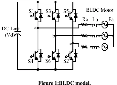
[image:2.595.71.265.475.617.2]It is assumed that the BLDC motor is connected to the output of the inverter, while the inverter input terminals are connected to a constant supply voltage, as shown in Figure1. Another assumption is that there are no power losses in the inverter and the 3-phase motor winding is connected in star. Brushless DC motor considered in this paper is a surface mounted, non-salient pole, permanent magnet (PM) synchronous machine with trapezoidal flux distribution in the air gap. This kind motor is very attractive in servo and/or variable speed application since it can produce a torque characteristic similar to that of a permanent magnet DC motor while avoiding the problems of failure of brushes and mechanical commutation.
Figure 1:BLDC model.
For a symmetrical winding and balanced system, the voltage equation across the motor winding is as follows:
Applying Kirchhoff’s voltage law for the three phase stator loop winding circuits’ yields:
(1)
(2)
(3)
Where
R Winding resistance per phase
La Self inductance per phase A
Lba Mutual inductance between phases B and A
ea Per phase A EMF
Va Per phase A voltage
Where the back-EMF waveforms ea, eb and ec are functions
of angular velocity of the rotor shaft, so
(4)
Where Keis the back-emf constant. So the BLDC motor mathematical model can be represented by the following equation in matrix form:
= -
(5)
If we assume that the rotor has a surface-mounted design, which is generally the case for today’s BLDC motors, there is no saliency such that the stator self inductances are independent of the rotor position, hence:
And the mutual inductances will have the form:
Assuming three phase balanced system, all the phase resistances are equal:
Rearranging the equation (5) yields;
= -
-
(6)
The electromechanical torque is expressed as
(7)
But the electromagnetic torque for this 3-phase BLDC motor is dependent on the current, speed and back-EMF waveforms, so the instantaneous electromagnetic torque can be represented as:
) (8)
3.
CLASSICAL SLIDING MODE
METHODOLOGY
represented by a switching function. Without lost of generality, consider the design of a SMC for the following second order system: (here u(t) is the input to the system) .
(9)
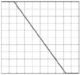
Where and constant factor Φdefines the thickness of the boundary layer.sat(s / Φ) is a saturation function that is defined as:
( ) { | | ( ) | | (10)
[image:3.595.96.237.240.372.2]The function between and s / Φis shown in the Figure2.
Figure 2: Switching surface in the phase plane.
[image:3.595.321.539.536.646.2]The control strategy adopted will guarantee a trajectory for the system that move toward the sliding surface S=0 and stay on from any initial condition if the following condition meets:
| | (11)
Where η is a positive constant that guarantees the system trajectories hit the sliding surface in finite time .Using a sign function often causes chattering in practice. One solution is to introduce a boundary layer around the switch surface.
This controller is actually a continuous approximation of the ideal relay control. The consequence of this control scheme is that invariance of sliding mode control is lost. The system robustness is a function of the width of the boundary layer.
The principle of designing sliding mode control law for arbitrary-order plants is to make the error and derivative of variables those are forced to zero. Switching surface design consists of the construction of the switching function. Thetransient response of the system is determined by this switching surface if the sliding mode exists. First, the position error is introduced: error of a variable is forced to zero. In the DC motor system the position error and its derivative are the selected coordinate
(12)
Where θref (k) and θ (k) are the respective responses of the
desired reference track and actual rotor position, at the k the sampling interval and e (k) is the position error. The sliding surface (s) is defined with the tracking error (e) and its integral (∫ e dt) and rate of change (ė).
(13)
Where λ1 ,λ2>0 are a strictly positive real constant. The basic control law of SMC is given by:
(14)
Where k is a constant parameter, sign (·) is the sign function and S is the switching function.
Also, the rotational speed is given by,
{ (15)
4.
DESIGN AND IMPLEMENTATION
OF FUZZY LOGIC CONTROLLER
There has been a significant and growing interest in the application of fuzzy logic control technique to control the complex, non-linear systems. Fuzzy logic is applied in applications like washing machines, subway systems,video cameras, sewing machines, biomedical and finance. Having understood the general behavior of the system,fuzzy logic enables the designer to describe the general behavior of the system in a linguistic manner by forming IFTHENrules which are in the form of statements.
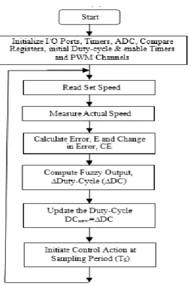
The great challenge is to design and implement the fuzzy logiccontroller (FLC) quickly with minimum number of rules based on the knowledge of the system. The general fuzzylogic controller consists of four parts as illustrated in Figure 3 to Figure 6 respectively. They are fuzzification, fuzzy rule-base,fuzzy inference engine and defuzzification. The design steps are as follows.
Step 1: Define inputs, outputs and universe of discourse
The inputs are error (E) and change in error (CE) and the output is change in duty-cycle (ΔDC). The error isdefined as the difference between the reference speed (Nref) and actual speed (Nact) and the change in error is definedas the difference between the present error e(k) and previous error e(k-1). The output, change in duty-cycle (ΔDC) is the new duty-cycle (DCnew) which is used to control the voltageapplied across the phase windings.
Figure 3: Block Diagram of Fuzzy Systems
The inputs andnew duty-cycle are described by, (16)
(17) (18)
for error can be defined to span between -4000 rpm to +4000 rpm. Based on the study of BLDC motor drive system, the universe ofdiscourse for change in error is chosen as +/-500 rpm. The maximum and minimum value for the change in dutycycleis defined as -100 % and +100 % respectively. To easily handle the large values for error and change in errorand reduce the computation time to achieve faster control action, the inputs and output are normalized.
Figure 4: Illustration for the formation of Rules for a typical under-damped system
Step 2: Defining fuzzy membership functions and rules
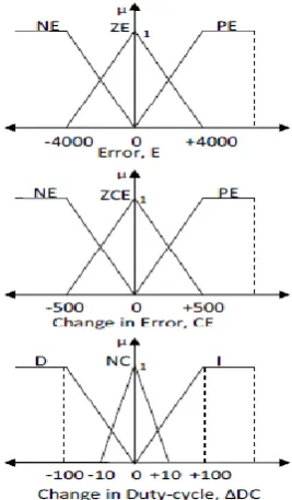
To perform fuzzy computation, the inputs must be converted from numerical or crisp value into fuzzy values andfinallyoutput should be converted from fuzzy value to crisp value. The fuzzy input variables “error” and “change inerror” are quantized using the following linguistic terms Negative (N), Zero (Z) and Positive (P). The fuzzy outputvariable change in duty-cycle is quantized using the following linguistic terms Decrease (D), No-change (NC) and Increase (I). Fuzzy membership functions are used as tools to convert crisp values to linguistic terms. A fuzzyvariable can contain several fuzzy subsets within, depending on how many linguistic terms are used. Each fuzzysubset represents one linguistic term. Each fuzzy subset allow its members to have different grade of membership,usually the membership value lies in the interval [0, 1]. In order to define fuzzy membership function, the designercan choose many different shapes based on their preference and experience. The popular shapes are triangular andtrapezoidal because these shapes are easy to represent designer’s ideas and requires less computation time. In orderto fine tune the controller for improving the performance, the adjacent fuzzy subsets are overlapped by about 25% orless. The membership functions used for inputs and output are shown in Figure 5.
Instead of using mathematical formula, FLC uses fuzzy rules to make a decision and generate the control action. The rules are in the form of IF-THEN statements. There are nine rules framed for this system and they are illustrated in Figure 4. The number of rules to be used to describe the system behavior is entirely based on the designer’s experience and the previous knowledge of the system. The performance of the controller can be improved by adjusting the membership function and rules. Fuzzy associative memories (FAM) are transformations which map fuzzy sets to fuzzy sets. A FAM matrix maps antecedents to consequents and is a collection of IF-THEN rules. Each composition involves three fuzzy variables and each fuzzy variable is further quantized into three. This has resulted in nine possible two input and single output FAM
[image:4.595.55.283.179.314.2]rules as illustrated in the Table 1. The nine rules formulated for the proposed fuzzy logic control system are listed below.
Figure 5: Membership functionsfor Error (E), Change in Error (CE) and Change in Duty-Cycle (ΔDC)
R1. IF Error (E) is Negative (NE) and Change in Error (CE) is Negative (NCE) THEN Change in duty-cycle (ΔDC) is Decrease (D).
This rule implies that when the system output is at R1, then the actual speed is greater than reference speed andthe motor is accelerating, so the duty-cycle of the IGBT’s of the Inverter module should be decreased so as to reducethe average voltage applied across the phase windings and bring the actual speed of the system close to referencespeed.
R2. IF E is Negative (NE) and CE is Zero (ZCE) THEN ΔDC is Decrease (D)
R3. IF E is Negative (NE) and CE is Positive (PCE) THEN ΔDC is Decrease (D)
R4. IF E is Zero (ZE) and CE is Negative (NCE) THEN ΔDC is Decrease (D)
R5. IF E is Zero (ZE) and CE is Zero (ZCE) THEN ΔDC is No-Change (NC).
This rule implies that when the system output is at R5, then there should be a no change in the duty-cycle as the actual speed has already reached steady-state.
R6. IF E is Zero (ZE) and CE is Positive (PCE) THEN ΔDC is Increase (I)
R7. IF E is Positive (PE) and CE is Positive (PCE) THEN ΔDC is Increase (I)
This rule implies that when the system output is at R7, then the actual speed is lesser than reference speed and the motor is decelerating, so the duty-cycle of the IGBT’s of the Inverter module should be increased so as to increase the average voltage applied across the phase windings and bring the actual speed of the system close to reference speed.
Figure 6: Flowchart for the fuzzy controller program
R9. IF E is Positive (PE) and CE is Negative (NCE) THEN ΔDC is Increase (I)
Finally the fuzzy output is converted into real value output i.e. crisp output by the process called defuzzification.Even though many defuzzification methods are available, the most preferred one is centroid method because thismethod can easily be implemented and requires less computation time when implemented in digital control systemsusing microcontrollers or digital signal processors (DSPs). The formula for this method is given by,
∑
∑ (19)
[image:5.595.49.274.592.687.2]Where z is the defuzzified value, L(x) is the membership value of member x. This crisp value is used to control theduty-cycle of the switching devices in the power inverter module so as to control the average voltage applied acrossthe phase windings, hence the speed of the motor.
Table 1. 3×3 FAM Matrix
E
CE NE ZE PE
CNE D D I
CZE D NC I
CPE D I I
5.
THE PROPOSED METHOD
Sliding mode controller has two main parts: equivalent controller, based on dynamics formulation andsliding surface saturation part based on saturation continuous function to reduce or eliminate the chattering. Reduce or eliminate the chattering regarding to reduce the error is play important role
inthis research. The proposed method is illustrated in figure 7. SMFC is fuzzy controller based on sliding mode method to easyimplementation, stability, and robustness.
Figure7: Sliding Mode Fuzzy Control (SMFC).
The system performance in this research is sensitive to the sliding surface slope λ input and output gainupdating factor Kα& Kβ for sliding mode fuzzy controller. Sliding surface
slope can change the response ofthe output if large value of λ is chosen the response is very fast but the system is very unstable andconversely, if small value of λ considered the response of system is very slow but the system is verystable. Determine the optimum value of λ for a system is one of the most important challenging works inSMFC. For nonlinear, uncertain, and time-variant plants on-line tuning method can be used to selfadjusting all coefficients. To keep the structure of the controller as simple as possible and to avoid heavycomputation, a new supervisor tuner based on updated by a new coefficient factor Kn is presented. In thismethod the supervisor part tunes the output scaling factors using gain online updating factors. The inputsof the supervisor term are error and change of error (e,ė) and the output of this controller is U, which it canbe used to tune sliding surface slope, λ.
| | (20)
(21)
{ (22)
In this way, the performance of the system is improved with respect to the SMFC controller. So the newcoefficient is calculated by;
(23)
(24)
6.
EXPERIMENTAL SET-UP
replaces the conventional bulky and expensive individual inverter switches and their associated driver and isolation circuits. The built-in hall sensors of the BLDC motorgenerate three hall sensor signals corresponding to rotor position. The duty-cycle of control signal is controlled based on the Fuzzy controller output so as control the terminal voltage of BLDC motor, and hence the speed of BLDC motor. This PWM control signal is ANDed with the commutation signals to generate gating signals for the IGBT switches. The PWM signals are generated for the switching devices using Event Manager-A module components such as timers, PWM channels, etc and applied to IGBT switches through pins PWM1-PWM6.
The expression for the average voltage applied across the winding is given by (25). The dc signal output of F/Vconverter is given as one of the input to analog to digital (A/D) converter of the DSP processor to determine the actual speed of the motor. The reference speed is set through a potentiometer and voltage follower and it is given as another input to the A/D converter to determine the reference speed. There is also another provision to set the reference speed from watch window of code composer studio software. The function of the DSP processor is to compute the error and change in error, store these values, compute the Fuzzy controller output, determine the new duty-cycle for the switching devices and perform electronic commutation.
The high speed digital buffer IC 74HCT244 is used to interface the DSP with the IGBT hybrid power module ICand the hall sensor circuit. The flowchart for the fuzzy controller program implemented in DSP is shown in Fig 6.
The control action time is chosen such that it is greater than one time constant of the motor so as to allow sufficient current through the windings and to produce the required torque during normal operation. The control action is initiated at every 1.5ms using Timer1.
(25)
[image:6.595.329.522.198.366.2]( ⁄ ) (26)
Figure 8: Experimental set-up of Fuzzy controller based BLDC motor drive
Where ton is turn on time, T is total time period of PWM signal, Vdc is the dc input voltage applied to the inverterand Vo(avg) is the average dc voltage applied across the phase windings.
6.1. Results and Discussions
The simulation of the BLDC motor was done using the software package MATLAB/SIMULINK. After running the simulation, the speed, torque, current, waveforms were recorded and analyzed.
Figure 9 shows the simulation result of both PI controller and SMFC controller. In this output, for any external disturbances SMFC controller is well settled within one second as compared to PI controller.
Figure 9:Simulated results comparison between the PIC and newSMFC of BLDC motor with external
disturbances.
In Figure10(a) and (b) presents the simulation results for the stator current, Electromagnetic Torque and Stator Back EMF under load and supply variations. From these results it is found that the simulated results of newSMFC shows better performance in comparison with a PI controller.
[image:6.595.59.272.459.659.2](b)
Figure 10(a) and (b): Simulated comparison results between the PIC and newSMFC controller of BLDC
[image:7.595.60.275.333.523.2]motor when varying the load.
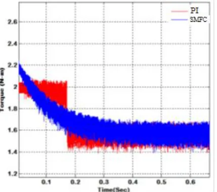
Figure 11:Simulated comparison results of torque between the PIC and SMFC controller of BLDC motor
Figure 11 shows the simulation results of PI controller and new SMFC controller when varying the input voltage. It demonstrates that satisfactory trajectory tracking is achieved effectively and the input chattering is eliminated completely by the method of slope adjusted SMFC controller. Finally, from the above simulated results of SMFC with BLDC drive has better performance over the PI controller.
7.
CONCLUSIONS
The slope adjustments in sliding mode fuzzy controllers are successfully implemented for the BLDC motor drive system and their performance is investigated with experimental results. It is foundthat SMFC based controller can successfully map the inputs with the corresponding outputs of the nonlinear BLDCmotor drive system without the knowledge of any predetermined model. Experimental results indicate that SMFC based BLDC motor drive system can track the error and makes the actual speed follow the reference speedwhen
the system is subjected to step change in reference speed, sudden load disturbance and parameter variations.
The design of fuzzy control technique does not require mathematical model of the system, but the rules have to beframed based on the knowledge of the system. It is possible to quickly and easily implement a fuzzy control techniqueeven for complex non-linear systems without their mathematical models. Finally the membership functions have to befine tuned to obtain better response. Even though, the fuzzy control technique works like an adaptivecontroller by adjusting its output according to the changing environment, it response becomes sluggish due toincrease in inertia and phase resistance.The steady state error of the fuzzy control system can be reduced by choosingproper membership functions and fine tuning the membership functions. Since fuzzy control system is robust, easilydesigned and implemented, effective in dealing with the uncertainties and parameter variations, and has better overallperformance, fuzzy control system may be preferred for automation, robotics, position and velocity control systems,and industrial control applications.
8.
ACKNOWLEDGMENTS
I would like to express my sincere gratitude to my research guide Prof. M.Sudha for the continuous support of my study and research. Her guidance helped me in all the time of research and preparing of this paper.
APPENDIX
SPECIFICATIONS OF BLDC MOTOR
Rated Voltage 36V
Rated Current 5A
No. of Poles 4
No. of Phases 3
Rated Speed 4000 rpm
Rated Torque 0.42 N-m
Torque Constant 0.082 N-m/A
Mass 1.25 kg
Inertia of Motor 23e-06 kg-m2
Resistance per phase 0.57Ω
Inductance per phase
6.5
mH
9. REFERENCES
[1] Pillay, P., and Krishnan, R. “Modeling, Simulation, and Analysis of Permanent-Magnet Motor Drives, Part II:The Brushless DC Motor Drive,” IEEE Trans. of Industry Applications, vol. 25, no. 2, pp. 274 – 279,March/April 1989.
[2] E. Cerruto, A. Consoli , A. Raciti, and A. Testa, “ A robust adaptive controller for PM motor drives in robotic application”, IEEE Trans. Ind. Applicat., vol. 28, pp. 448-454, Mar-April 1992.
[4] Shanmugasundram, R., Zakariah, K.M., and Yadaiah, N. “Modelling, simulation and analysis of controllers for brushless direct current motor drives,” Journal of Vibration and Control [online], vol. 0, no. 0, pp. 1-15, May2012.
[5] Wallace, A.K., and Spee, R. “The effects of motor parameters on the performance of brushless DC drives,” IEEE Trans. on Power Electronics, vol. 5, no. 1, pp.2-8, Jan.1990.
[6] Varatharaju, V.M., Mathur, B.L., and Udhyakumar, K. “Speed control of PMBLDC motor using MATLAB/Simulink and effects of load and inertia changes,” Proc. of 2010 2nd International Conf. on Mechanical and Electrical Technology (ICMET), Singapore, pp. 543 – 548, 10-12 Sept. 2010.
[7] Basilio, J.C., and Matos, S.R. “Design of PI and PID Controllers with Transient Performance Specification,” IEEE Trans. on Education, vol. 45, no. 4, pp. 364-370, Nov.2002.
[8] Krohling, R. A., Jaschek, H., and Rey, J. P. “Designing PI/PID controller for a motion control system based ongenetic algorithm,” Proc. 12th IEEE Int. Symp. Intell. Contr., Istanbul, Turkey, pp. 125–130, July 1997.
[9] AtefSaleh Othman Al-Mashakbeh,” Proportional Integral and Derivative Control of Brushless DC Motor,” European Journal of Scientific Research, Vol.35 No.2 (2009), pp.198-203.
[10]K. D. Young, V. I. Utkin, and Ü. Özgüner, “A control engineer's guide to sliding mode control,” IEEE Trans. Control Sys. Tech., vol. 7, 1999, pp. 328-342.
[11]A. Sabanovic and F. Bilalovic, “Sliding mode control of AC drives,” IEEE Trans. Ind. Appl.,vol. 25, no. 1, pp. 70-75, Jan.-Feb. 1989.
[12]Y. J. Huang and H. K. Wei, “Sliding mode control design for discrete multivariable systems with time-delayed input signals,” Intern. J. Syst. Sci., vol. 33, 2002, pp. 789-798.
[13]Yan Xiaojuan, Liu Jinglin,”A Novel Sliding Mode Control for BLDC Motor Network Control System,” 3rd International Conference on Advanced Computer Theory and Engineering (ICACTE), 2010.
[14]T. C. Kuo,Y. J. Huang,C. Y. Chen, and C. H. Chang,”Adaptive Sliding Mode Control with PID Tuning for Uncertain Systems,”Engineering Letters,16:3,2008.
[15]Pierre Guillemin “Fuzzy Logic Applied to Motor Control,” IEEE Trans. on Ind., Appl., vol. 32, no. 1, pp. 51-56, Jan./Feb. 1996.
[16]Rubaai, A., Ricketts, D., and Kankam, M. D. “Laboratory implementation of a microprocessor-based fuzzy logic tracking controller for motion controls and drives,” IEEE Trans. Ind., Appl., vol. 38, no. 2, pp. 448– 456, Mar./Apr. 2002.
[17]Fernando Rodriguez, and Ali Emadi “A Novel Digital Control Technique for Brushless DC Motor Drives,” IEEE Trans. on Industrial Electronics, vol. 54, no. 5, pp. 2365-2373, Oct. 2007.
[18]Yen-Shin Lai, Fu-san Shyu, Yung-Hsin Chang “Novel Loss Reduction Pulse width Modulation Technique for Brushless DC Motor Drives fed by MOSFET Inverter,” IEEE Trans. Power Electronics, vol. 19, no. 6, pp. 1646-1652, Nov. 2004.