Artificial Neural Networks based UPFC for Damping
Low Frequency Oscillations
Sangu Ravindra
Associate Professor Department of EEE QISCET, Ongole
V.C.Veera Reddy,
Ph.DProfessor Department of EEE S.V.University, Tirupathi.
S.Sivanagaraju,
Ph.DAssociate Professor Department of EEE JNTUK, Kakinada
ABSTRACT
Low Frequency Oscillations(LFO) are a frequent adverse phenomenon which increase the risk of instability for the power system and thus reduce the total and availability transfer capability.LFO occur in power systems because of lack of the damping torque in order to dominance to power system disturbances as change in mechanical input power. In the recent past Power System Stabilizer (PSS) was used to damp LFO. FACTs devices, such as Unified Power Flow Controller (UPFC), can control power flow and increase transient stability. So UPFC may be used to damp LFO instead of PSS. In this research the linearized model of synchronous machine (Heffron-Philips) connected to infinite bus (Single Machine-Infinite Bus: SMIB) with UPFC is used and also in order to damp LFO, adaptive ANN damping controller for UPFC is designed and simulated. Simulation is performed for various types of loads and for different disturbances. Simulation results demonstrate that the developed ANN damping controller would be more effective in damping electromechanical oscillations in comparison with the conventional lead-lag controller.
Keywords
Low Frequency Oscillations (LFO), Unified Power Flow Controller (UPFC), Single Machine-Infinite Bus (SMIB) power system, Artificial Neural Network (ANN) damping controller.
1.
INTRODUCTION
The Benefits of Flexible AC Transmission Systems (FACTs) usages to improve power systems stability are well known [1]. The growth of the demand for electrical energy leads to loading the transmission system near their limits. Thus, the occurrence of the LFO has increased. FACTs controllers has capability to control network conditions quickly and this feature of FACTs can be used to improve power system stability. The UPFC is a FACTS device that can be used to the LFO. The UPFC consists of two voltage source converters (VSC) each of them has two control parameters namely me, δe, mb and δb [2]. The UPFC used for power flow
control, enhancement of transient stability, mitigation of system oscillations and voltage regulation. A comprehensive and systematic approach for mathematical modeling of UPFC for steady-state and small signal (linearized) dynamic studies has been proposed in [3] and [4]. The other modified linearized Heffron-Philips model of a power system installed with UPFC is presented in [5]. For systems which are without power system stabilizer (PSS), excellent damping can be achieved via proper controller design for UPFC parameters. By designing a suitable UPFC controller, an effective damping can be achieved. It is usual that Heffron-Philips model is used in power system to study small signal
stability. This model has been used for many years providing reliable results [6].
In order to damp low frequency oscillations, in this paper, the adaptive ANN controller [9], [10] is designed and simulated. Matlab toolbox is used as a computing tool to implement the ANN. To show performance of the designed adaptive artificial neural network controller, a conventional lead-lag controller that is designed in [7] is used and the simulation results for the power system including these two controllers are compared with each other.
2. POWER SYSTEM MODELING WITH
UPFC
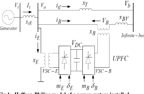
UPFC is one of the famous FACTs devices that is used to improve power system stability. Fig.1 shows a single machine-infinite-bus (SMIB) system with UPFC. It is assumed that the UPFC performance is based on pulse width modulation (PWM) converters. In figure 1 me, mb and δe, δb
[image:1.595.324.564.470.627.2]are the amplitude modulation ratio and phase angle of the reference voltage of each voltage source converter respectively. These values are the input control signals of the UPFC.
Fig 1: Heffron-Philips model of a power system installed with UPFC
As it mentioned previously, a linearized model of the power system is used in dynamic studies of power system. In order to consider the effect of UPFC in damping of LFO, the dynamic model of the UPFC is employed [8]. In this model the resistance and transient of the transformers of the UPFC can be ignored.
The system’s dynamic relations are expressed as follows:
o
M D P
Pm e )/
(
do fd
q E T
E q
E ( )/
) ( 1 t to A A fd A
fd v v
T K E T
E
(1)
There exit several models for UPFC depending on several study cases.The following equation describe the dynamic behavior of UPFC :
2
sin
2
cos
0
0
E dc E E dc E Eq Ed E E Etq Etdv
m
v
m
i
i
x
x
v
v
(2)
2
sin
2
cos
0
0
B dc B B dc B Bq Bd B B Btq Btdv
m
v
m
i
i
x
x
v
v
(3)
Bq Bd B B dc B Eq Ed E E dc E dc i i C m i i C m dtdv
sin cos 4 3 sin cos 4 3 (4)
By combining the above linear dynamic equations ,The state equations expressed as follows:
BU AX
X= + (5) Where the matrixces
(6)
B B E Em
m
U
(7)
Where ∆mE, ∆δE, ∆mB and, ∆δB are the variations of UPFC control parameters considered as the inputs of state space model.
9 8 7 6 5 ' 0 ' 0 ' 0 3 ' 0 4 2 10
0
1
0
1
0
0
0
0
0
0
k
k
k
T
k
k
T
T
k
k
T
k
k
T
k
T
T
k
T
k
M
k
M
k
M
D
M
k
A
A vd A A A A A A d qd d d d pd o
(8)
b c cb e c ce A b v A A vb A A e v A A ve A d b q d qb d e q d qe b p pb e p pek
k
k
k
T
k
k
T
k
k
T
k
k
T
k
k
T
k
T
k
T
k
T
k
M
k
M
k
M
k
M
k
B
' 0 ' 0 ' 0 ' 00
0
0
0
(9) The k coefficients are obtained during the Linearization of (1) and (2) around the operating point.
3. DESIGN OF DAMPING
CONTROLLERS
3.1 Lead-Lag Controller Design
As mentioned before, in this study two different controllers have been used to damp LFO. The first one is conventional lead-lag controller. It consists of gain block, washout block, lead-lag compensator block. The washout block is considered as a high-pass filter, with the time constant TW. Without this block steady changes in input would modify the output. The value of TW is not critical and may be in the range of 1 to 20 seconds. In this study, the parameters obtained from lead-lag controller design that is presented in [7], were used.
3.2 Adaptive Artificial Neural Networks
Controller Design
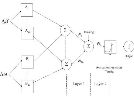
Fig 2: ANN Architecture for a two input sugeno model with two rules
For the training data the error reducing method is the following steps are taken those are
1. Set the Learning Rate Parameter (ŋ) is greater than the one
and error value E=0.
2. First Layer k =1.
3. Calculate the output value
fi (n) = tansig (<Wi (µ(∆δ )+µ(∆ω) )>)+ r ;
for i=1,2,…20.
4. Calculate error E=E+1/2||f - fi (n)||2.
5. Weights are updated
Wi+1 = Wi + ŋ (f-tansig(<Wi (µ(∆δ )+µ(∆ω))>) + r);
for i=1,2..20.
6. Check error E is not zero, then take the layer value as
k =k+1,
7. Repeat the above process until when the error E as zero.
From above process we get the desired output function, the output function
f =(1-e-(Wi (µ(∆δ )+µ(∆ω))+r) /(1+e-(Wi (µ(∆δ )+µ(∆ω))+r)
The range of output function is -1 to +1.
4. SIMULATION RESULTS
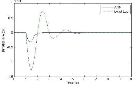
In this research, two different cases are studied. In the first case mechanical power and in the second case reference voltage has step change and deviation in ω (Δω) and deviation in rotor angle δ (Δδ) is observed. The parameter values of system are gathered in Appendix. In first case, step change in mechanical input power is studied. Simulations are performed when mechanical input power has 10% increase (ΔPm=0.1 Pu) at t = 1s. Simulation results for different types of loads and controllers (ΔmE, ΔδE, ΔmB, ΔδB)
and step change in mechanical input power are shown in figures 3 to 7.
Fig 3: Angular velocity deviation during step change in mechanical input power for nominal load
(me Controller).
Fig4: Angular velocity deviation during step change in mechanical input power for light load
[image:3.595.330.545.78.225.2](me Controller).
Fig 5: Angular velocity deviation during step change in mechanical input power for nominal load
[image:3.595.260.541.81.673.2]Fig 6: Angular velocity deviation during step change in mechanical input power for nominal
load (mb Controller)
Fig.7 Angular velocity deviation during step change in mechanical input power for nominal load
(δb Controller).
As it can be seen from figures 3 to 7, lead-lag controller response is not as good as ANN damping controller response and also ANN damping controller decreases settling time. In addition maximum overshoot has decreased in comparison with lead-lag controller response.
In second case, simulations were performed when reference voltage has 5% increase (ΔVref =0.05 Pu) at t=1s. Figure 8 demonstrates simulation result for step change in reference voltage, under nominal load and for δb Controller.
Consequently simulation results show that ANN damping controller successfully increases damping rate and decreases the amplitude of low frequency oscillations. Results comparison between conventional lead-lag compensator and the proposed ANN damping controller for the UPFC indicates that the proposed ANN damping controller has less settling time and less overshoot in comparison with the conventional lead lag compensator.
5. CONCLUSIONS
With regard to UPFC capability in transient stability improvement and damping LFO of power systems, an adaptive ANN damping controller for UPFC was presented in this paper. The controller was designed for a single machine infinite bus system. Then simulation results for the system including ANN damping controller were compared with simulation results for the system including conventional lead-lag controller. Simulations were performed for different kinds of loads. Comparison showed that the proposed adaptive ANN damping controller has good ability to reduce settling time and reduce amplitude of LFO.
6. APPENDIX
Generator: M = 2H = 8.0MJ / MVA, D=0.0, T’do = 5.044s, Xd = 1.0 pu, Xq = 0.6pu , X’d = 0.3pu
Exciter (IEEE Type ST1): KA=100, TA=0.01s
Reactance’s: XlE = 0.1pu, XE = XB = 0.1pu XBv= 0.3pu, X e = 0.5pu
Operation Condition: Pe = 0.8pu, Vt = 1pu, Vb = 1pu UPFC parameters: mE = 0.4013, mB = .0789, δE = - 85.3478
0
δB = - 78.2174 0
DC link: Vdc = 2pu, Cdc=1pu
7. REFERENCES
[1] N. G. Hingorani and L. Gyugyi, Understanding FACTS: Concepts and Technology of Flexible AC Transmission System, IEEE Press, 2000.
[2] Noroozian, M., Angquist, L., Ghandhari, M., Andersson, G., "Use of UPFC for optimal power flow control," Power Delivery, IEEE Transactions on, vol.12, no.4, pp.1629-1634, Oct 1997.
[3] Stefanov, P.C., Stankovic, A.M., "Modeling of UPFC operation under unbalanced conditions with dynamic phasors," Power Systems, IEEE Transactions on, vol.17, no.2, pp.395-403, May 2002.
[4] Wang, H.F., "Damping function of unified power flow controller," Generation, Transmission and Distribution, IEE Proceedings- , vol.146, no.1, pp.81-87, Jan 1999.
[5] Wang, H.F., Swift, F.J., "A unified model for the analysis of FACTS devices in damping power system oscillations. I. Single-machine infinite-bus power systems", Power Delivery, IEEE Transactions on, vol.12, no.2, pp.941-946, Apr 1997.
[6] P. Kundur,"Power System Stability and Control”,
McGraw-Hill.
[image:4.595.68.283.77.229.2] [image:4.595.63.279.590.728.2]controller", 39th International Universities Power Engineering Conference, 2004, pp. 265 – 269.
[9] Atmakuru, R., Kumar, R.S., "ANN based adaptive control coordination of PSSs and FACTS devices in multi-machine power systems", Modern Electric Power Systems (MEPS), 2010 Proceedings of the International Symposium , vol., no., pp.1-7, 20-22 Sept. 2010.
[10] Tsao-Tsung Ma, “Multiple Upfc Damping Control Scheme Using Ann Coordinated Adaptive Controllers”, Asian Journal of Control, Vol. 11, No. 5, pp. 489- 502, September 2009.
[11] Nguyen, T.T., Gianto, R., 2008 "Neural networks for adaptive control coordination of PSSs and FACTS devices in multimachine power system," Generation, Transmission & Distribution, IET , vol.2, no.3, pp.355-372, May 2008.
BIBLIOGRAPHY
Mr. Sangu Ravindra received his B.Tech in Electrical Engineering from JNT University, Hyderabad & M.E in Power Electronics & Indstrial Drives from Satyabhama
University, Chennai. He is now a Ph.D candidate at JNT University, Kakinada. His research interest area is FACTS controllers for power quality improvement. Presently he is working as Associate Professor in department of EEE at QISCET ongole.
Dr.V.C.Veera Reddy received his B.Tech in Electrical Engineering from JNT University, Anantapur in 1979 & M.Tech in Power System Operation & Control from S.V University Tirupati, in 1981. He got Ph.D degree in Modeling & Control of Load Frequency using new optimal control strategy from S.V. University Tirutati, in 1999. Presently he is working as Professor of EEE S.V.U.College of Engineering, S.V.University Tirupati-517502.