Intelligent Induction Motor Drive
Rohit Gupta
EIED, Thapar University
Thapar University, Patiala
Punjab, India
Ruchika
EIED, Thapar University
Thapar University, Patiala
Punjab, India
ABSTRACT
Electrical drives play an important role in rapidly growing industrial era, so the controlling of electrical drives is also important. Variable speed drives are the major part of power system, microelectronic, power plant and so on. Conventional controlling methods of electrical drives needed mathematical model of control process which was very tedious, that problem is solved by artificial intelligence which contains both hard computation and soft computation. Artificial intelligence has found high application in most nonlinear systems same as motor drive. As no mathematical model is needed for artificial intelligent system so efficiency and reliability of drives increase and volume, weight and cost of drives decrease. Soft starters are widely used with electronic motor as it provides improved operating characteristics and better control. Soft starter also reduces the wear and tear effects on motor and their associated drive systems which in turn reduces maintenance, conserve energy and plays a significant part in improving system performance so the escalators, pumps, elevators and conveyor belts can be operated more effectively with soft starter.
Keywords
Artificial Intelligence, Induction Motor, Soft starting
1.
INTRODUCTION
To improve the productivity of manufacturing industry, sophistication in factory automation is very much needed. In manufacturing process, variable speed drives plays an important role and occupies a major part in terms of conveyor belts, robot arms, overhead cranes, steel process lines, paper mills and plastic and fiber processing units etc. In early fifties, all the above given applications were run through DC motors as at that time AC motors were not capable of smoothly varying speed since they operated synchronously or almost synchronously with the frequency of electrical input, but now all these applications are served by so called general purpose AC drives as they much cheaper than DC drives and in addition AC drives offers less maintenance cost, highly reduced size and improved reliability. The only disadvantage with the AC drive is that very limited control flexibility is available and their application is restricted to fan, pump, and compressor type of application where the speed need to be regulated only roughly and transient response and low-speed performance are not critical. DC drives can be designed as per the application needed with the wide variety of AC-DC converter available, however induction motor drives have been shown to be more than a match for DC drives in high-performance applications though control of induction motor is more complicated than DC motor drives but with the advancement of microelectronics, one can overcome these complexities.
2.
SPEED CONTROL PRINCIPLE
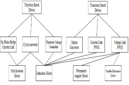
AC motor drives can be subdivided into two categories: 1. Thyristor based drives.
2. Transistor based drives.
[image:1.595.317.544.539.689.2]Thyristor has the capability of self turn-on by an associated gate signal but its turn off depends upon circuit conditions. On the other hand, transistor devices are capable of both turn-on and turn-off. A switching or commutation device is must with thyristor based drives which utilize an alternating EMF to accomplish the switching action in order to turn on and off the gate signal [1]. Normally induction motors are fixed speed drives, but there are two methods to change the rotation speed of AC induction motors. First is to use frequency converter to vary the speed and second is by using separate windings for different speeds. Using separate windings for different speed is not an advisable method as it will not provide accurate speed control and is also costly. For accurate control, frequency converter is advisable as it can run a three phase AC drive at very wide range but the performance of drive normally degrades as it is used outside its optimal operational speed. While selecting the frequency drive for induction motor, one should take care of the mechanical load and speed range, otherwise the motor can get very hot because a motor for 60 Hz does not have enough iron in it to allow efficient 25 Hz operation and if the frequency drops down to 10 Hz, it would make it even worse. For variable frequency drive, manufacturer used different type of alloys for motor so that the motor can be used at various frequencies. A good variable frequency drive can be designed with light mechanical load and appropriate motor selection, and it is possible to get wide speed range with a variable frequency inverter. From above discussion, it can be concluded that a good frequency drive is that device which control both the frequency and voltage.
Figure 1 shows the different types of drive available according to their switching nature i.e. natural and forced commuted. An external voltage source is required to accomplish turn-off of the switches in naturally commutated device. On the other hand, force commutated device uses a low power gate signal or base voltage signal which starts the turn-off mechanism in the switch. There are many drive types and for each type of drive, numerous types of speed control methods are available, all of them cannot be discussed here. However, there are four major types of drive available and there speed control methods are as follows:-
1. Vector controlled permanent magnate motor drives. 2. Load commutated synchronous motor drives 3. Volts per hertz and vector controlled induction
motor drives.
4. Voltage controlled induction motor drives.
[image:2.595.317.543.172.378.2]Figure 2 shows the block diagram of induction motor control in which rectifier and inverter unit can be of various types. In Figure 3 schematic diagram of three phase induction motor control in which transistors are used in inverter circuit is shown, so it can be said as a transistor based induction motor drive.
Fig 2: Induction motor control block diagram
Fig 3: Schematic of transistor based induction motor drive
3.
SOFT STARTING
Starting torque plays an important role in case of driving high-inertial loads. Several studies have been done to improve starting properties of an induction motor [2-5]. During starting period, slip is equal to unity by considering the equivalent circuit of an induction motor, so the input impedance seen from supply side has the lowest value, because of that a very high current is drawn by motor during starting period, therefore it is always recommended to use the drivers which limit the starting current [6-8], and when motor starts directly i.e. without starter, the torque surge problem will be encountered in which drive puts extra stress on the gearbox, couplings, belt driver and other parts and that will lead to wear and even failure.
To overcome starting current and torque surge problem, there are various types of systems available. Some of them are:-
1. Direct on-line starting system. 2. Star-delta starting system.
3. Frequency conversion starting system. 4. Soft starting system.
Up to 7.5kW, direct on-line starting method is preferred for higher currents and some form of start-up reduction is
required. In star delta arrangement, as the name suggests the motor windings are switched to delta connection from star connection ,so as a result the start-up current and torque both are reduced by two third but for that extra TDTP switch is required. The only drawback with star delta starting system is that at switching point, there is still a current surge that can be as high as experienced in direct online starting. To overcome these drawbacks of direct online starting, star delta frequency conversion method can be used which takes the AC voltage, converts that to DC and then to start-up, voltage of desired frequency is used, but it is very complicated and costly as well.
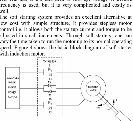
[image:2.595.321.543.274.389.2]The soft starting system provides an excellent alternative at low cost with simple structure. It provides stepless motor control i.e. it allows both the startup current and torque to be adjusted in small increments. Through soft starters, one can vary the time taken to run the motor up to its normal operating speed. Figure 4 shows the basic block diagram of soft starter with induction motor.
Fig 4: Basic Soft Starter with induction motor
[image:2.595.65.279.391.495.2]Soft starters allow the machine to start, vary its speed and stop with minimum mechanical electric stresses on the equipment. This can be done by appropriate adjustment of the induction motor terminal voltage. However, adjusting the voltage for a given operating condition of speed and torque is not a simple task. To adjust the voltage, the firing angle α of the thyristor is to be calculated for each operating condition. Firing angle is a nonlinear function of motor speed and torque and it is very difficult to find the exact value of α for any motor speed and torque. Some methods of closed loop control technique to achieve this have been developed and presented in [9]. In this method, speed sensor is required to acquire the signal feedback. Some researchers have proposed and developed a method of optimal soft starting without a speed sensor in which sensing of thyristors voltages is very much required [10, 11]. Soft starter drives includes the benefits like longer motor life, reduced maintenance and improved torque control because of that, its application areas are increasing rapidly.
4.
CONTROL PRINCIPLE
stability and allow different design objectives such as steady state and transient characteristics of closed loop system, but for that correct mathematical model of the system should be known. On the other hand, while using artificial control tools it is not necessary to know the mathematical model of the system and also the uncertainty or unknown variations in plant parameters and structure can be dealt more effectively. Several works contributed to the design of hybrid control schemes [12].
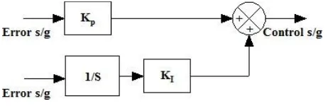
[image:3.595.320.541.149.291.2]In this paper, both control methods (conventional and artificial intelligent) are introduced and applied to an indirect field-oriented induction motor. In first type of approach, a conventional PI controller is introduced in order to achieve speed control and starting situation is observed. The structure of PI controller used is shown in Figure 5 which is a regular parallel PI controller.
Fig 5: Conventional PI controller structure
[image:3.595.54.285.247.322.2]In second approach, which is artificial intelligence based controller i.e. fuzzy logic controller, for which linguistic IF-THEN rules are used as a set of controller rule base is introduced. The structure of fuzzy logic controller used is shown in Figure 6.
Fig 6: Fuzzy PI controller structure
Fuzzy logic controller based control strategy shows better result because fuzzy logic overcomes the mathematical difficulties of modeling of highly non-linear systems, it responds in a more stable fashion to imprecise readings of feedback control parameters, such as dc link current and voltage, its modification is very easy and it is very flexible.
5. VECTOR CONTROLED INDUCTION
MOTOR DRIVE
Traditional control methods, such as v/f control methods control the frequency and amplitude of the motor drive voltage whereas vector control methods control the frequency, amplitude and phase of the motor drive voltage. The key principle of vector control is to generate 3-phase voltage as a phasor to control the 3-phase stator current as a phasor that controls the rotor flux vector and finally the rotor current phasor. Ultimately, the components of the rotor current need to be controlled. The rotor current cannot be measured because there is no direct electrical connection. So, they are indirectly computed using the parameters that can be measured. This technique is indirect vector control because there is no access to rotor currents. Indirect vector control is accomplished using the following data:-
1. Instantaneous stator phase currents. 2. Rotor mechanical velocity. 3. Rotor electrical time constant.
[image:3.595.57.282.414.495.2]The motor must be equipped with sensors to monitor the 3-phase stator currents and rotor speed for feedback. Figure 7 shows the block diagram of vector controlled induction motor.
Fig 7: Block diagram of vector controlled induction motor
Following are the steps required for indirect vector control:- 1. 3-phase stator currents (Ia, Ib, Ic) and rotor speed are
measured.
2. The 3-phase stator currents are transformed to a 2-axis time varying quadrature current values (Iα, Iβ)
as viewed from the stator perspective.
3. The 2-axis coordinate system is rotated to align with the rotor flux using transformation angle information calculated at the last iteration of the control loop. This conversion provides quadrature components of currents (Id, Iq) transformed to the
rotating co-ordinate system. Id and Iq will be
constant at steady-state.
4. Id reference controls rotor magnetizing flux. Iq
reference controls the torque output of the motor. The error signals computed after comparison are input to PI controllers. The output of the controllers provides Vd and Vq, which is a voltage vector.
5. A new coordinate transformation angle is calculated. The motor speed, rotor electrical time constant, Id and Iq are the inputs to this calculation.
The new angle tells the algorithm where to place the next voltage vector to produce an amount of slip for the present operating conditions.
6. The Vd and Vq output values from the PI controllers
are rotated back to the stationary reference frame using the new angle. This results in the quadrature voltage values Vα and Vβ.
7. The Vα and Vβ are transformed back to 3-phase
values Va, Vb and Vc. These 3-phase voltage values
are used to calculate new PWM duty cycle values that generate the desired voltage vector.
5.
INTELLIGENT SPEED CONTROL
The structure of intelligent speed controller or fuzzy controller is shown in Figure 6, in which K1, K2, and K3 are known as
well-defined method for good setting of scaling factors for fuzzy logic controllers. But the scaling factors are the main parameters used for tuning the fuzzy logic controller because changing the scaling factors changes the normalized universe of discourse, the domains, and the membership functions of input /output variables of fuzzy logic controller.
[image:4.595.55.283.166.300.2]Figure 8 shows the block diagram of fuzzy logic controller in which the steps involved in the fuzzy controller are shown.
Fig 8: Fuzzy inference system for fuzzy controller
K1 and K2 are scaling factors for the input where as K3 is the
scaling factor for the output. In this design, the input and output scaling factors are determined by trial and error methods and are taken very small. The mamdani based fuzzy inference system uses linear membership function for both inputs and outputs. The ranges of the values are normalized between -1 to 1. Figure 9 shows the membership functions for the inputs i.e. error and change in error and output which is controlling signal.
Fig 9: Membership functions for inputs and output
[image:4.595.321.539.416.620.2]The linguistic variables used in the membership functions are described in Table 1.
Table 1. Linguistic variables in fuzzy inference system
Error Change in error Controlling
Signal
NB Negative
Big NB
Negative
Big NB
Negative Big
NM Negative
Medium NM
Negative
Medium NM
Negative Medium
NS Negative
Small NS
Negative
Small NS
Negative Small
Z Zero Z Zero Z Zero
PS Positive
Small PS
Positive
Small PS
Positive Small
PM Positive
Medium PM
Positive
Medium PM
Positive Medium
PB Positive
Big PB
Positive
Big PB
Positive Big
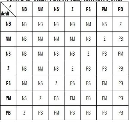
In mamdani based fuzzy inference system IF-THEN rules are created. The IF-THEN rules of mamdani type fuzzy inference system is summarized in Table 2.
Table 2.IF-THEN rules for fuzzy inference system
[image:4.595.319.540.421.621.2] [image:4.595.70.264.438.640.2]
Fig 10: Crisp inputs/ output map
6.
SIMULATION RESULT
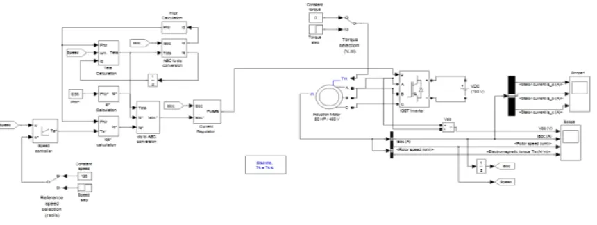
In this paper, two case studies have been taken. In Both simulations, simulink and powersim toolboxes of MATLAB software are used. In the first case study, a 50 HP induction
motor is started and controlled by a PI controller whose simulink model is shown in Figure 11.
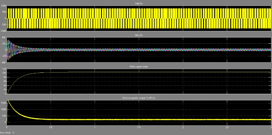
3 phase voltages and currents are measured and plotted in the first 3 seconds of its action. Also acceleration curve and output torque is investigated. All graphs are shown in Figure 12. In the second case, the same motor is started and controlled by a Fuzzy Logic Based controller whose simulink model is shown in Figure 13 and the results are shown in Figure 14.
As it is shown, the outputs are improved regarding the magnitude of starting currents and also time response of acceleration. For example, amplitude of current with a classic PI controller is about 500 A during startup while with fuzzy logic controller this value reduced to 300 A.
[image:5.595.89.519.326.488.2]Fuzzy logic controller makes the system inherent to uncertainty if we observe the speed waveform in Figure 15 then we find that at time t= 1.06 sec. a disturbance in terms of load torque is introduced in the system for which fuzzy based PI controller performs well as compared to conventional PI controller, thus fuzzy based PI controller provides a robust control.
[image:5.595.55.531.529.731.2]Fig 11: Simulink model of conventional PI controller based induction motor control
Fig 13: Simulink model of fuzzy PI controller based induction motor control
Fig 14: Simulation result of fuzzy PI controller based induction motor control
[image:6.595.141.442.526.706.2]7.
CONCLUSION
An induction motor consumes more energy than it actually needs to perform its work when operated at less than full load condition, that excess energy gets radiated in form of heat. By introducing the artificial intelligence in the system, one can control the amplitude of starting current and save the energy and also the new intelligent control structure is insensitive to disturbance generated outside or within the system. In addition, Fuzzy logic controller based control strategy shows better result because fuzzy logic overcomes the mathematical difficulties of modeling of highly non-linear systems, the cost and complexity of the controller is reduced and it responds in a more stable fashion to imprecise readings of feedback control parameters, such as dc link current and voltage, its modification is very easy and it is very flexible. In future some optimization technique can be used to optimize the number of rule base used in the Fuzzy logic controller, as time consumed in fuzzyfication and defuzzyfucation is very much depends on the number of rules which in turn effect the response of the controller.
8.
REFERENCES
[1] Bimal Bose 2006. Power Electronics and Motor Drives advances and Trends, 1st edition, Elsevier Academic Press.
[2] Say, M. 1984 Alternating Current Machines. 2nd Edition, Pitman, England.
[3] Badr, M. A., Abdel Halim, M. A., and Alolah, A. I. 1996 A Nonconventional Method for Fast Starting of Three Phase Wound-Rotor Induction Motors. IEEE Trans. On Energy Conversion Vol. 11, pp. 701-707.
[4] Abdel Halim, M. A., Badr, M. A., and Alolah, A. I. 1997 Smooth starting of slip ring induction motors. IEEE Trans. On Energy Conversion Vol. 12, pp. 317-322.
[5] Hamouda, R. M., Alolah, A. I., Badr, M. A., and Abdel Halim, M. A. 1999 A Comparative Study on the Starting Methodes of Three Phase Wound-Rotor Induction
Motors part I. IEEE Trans. On Energy Conversion Vol. 14, pp. 918-922.
[6] Zenginobuz, G., Cadirci, I., Ermis, M., and Barlak, C. 2001. Soft Starting of Large Induction Motors at Constant Current with Minimized Starting Torque Pulsations. IEEE Trans. On Industry Applications Vol. 37, pp. 1334-1347.
[7] Rashad, E. M., Radwan, T. S., and Rahman, M. A. 2004. Starting and Vector Control of Series-Connected Wound-Rotor Induction Motor in Super Synchronous Mode. 39th IAS Annual Meeting Conference on Industry Applications Vol. 1, pp. 32-39.
[8] Li, W. X., Lu, J. G., Liu, M. S., and Zhao, J. 2004. Design of Intelligent Soft-Start Controller for Induction Motor. Proceedings of 3rd International Conference on
Machine Learning and Cybernetics Vol. 2, pp. 908-912.
[9] Denai, M. A., and Attia, S. A. 2002. Fuzzy and Neural Control of an Induction Motor. International Journal Appl. Math. Computer Sci Vol. 12.
[10]Cleland, J. G., and Tumer, M. W. Fuzzy Logic Control of Electric Motors and Motors Drives Feasibility Study. United States Air and Energy Engineering Environmental Protection Research Laboratory Agency Research Triangle Park.
[11]Shen, J. X., Zhu, Z. Q., Howe, D., and Buckley, J. M. 2002. Adaptive Fuzzy Logic Speed Control of PM Brushless AC Drives. International Conference on Power Electronics Machines and Drives, pp. 68-73.
[12]Dannenberg, A. 2005. Fuzzy Logic Motor Control with MSP430x14x. Texas Instruments, Application Report, SLAA235.