AN APPROACH OF CORRECTING THE ERRORS IN THE
VISION NAVIGATION SYSTEM FOR FIELD ROBOT
1ZHIBIN ZHANG, 2YONGSHENG SONG, 3HAIXU WANG, 4XIAOYAN REN
1
Computer Science School, Inner Mongolia University, China
2Computer Science School, Inner Mongolia University, China 3Computer Science School, Inner Mongolia University, China 4Computer Science School, Inner Mongolia University, China
E-mail: [email protected], [email protected],
3 [email protected], 4 [email protected]
ABSTRACT
In the vision navigation system, the transformation from image coordinates to world coordinates is the essential part for the autonomous robot field based on crop rows detection using single camera. An approach of correcting the errors of the vision system is proposed in this paper, which can correct the errors of the target coordinates on the ground according to the theory of the lens distortion and coordinate transformations, and furthermore, the third-order B spline interpolation was used to improve the performance of the vision navigation system for the field autonomous robot. The experiment was implemented using the data obtained from the target board image, and the experimental results show that the approach proposed in this paper is effective.
Keywords: Lens Distortion, Coordinates Transformation, Vision Navigation, Field Robot
1. INTRODUCTION
It has been a long time since people began to utilizing machine vision in agricultural vision navigation. For the purpose of evaluating the accuracy and stability, the imaging characteristics, grey scale characteristics and structural characteristics of the crop rows are all used in the vision navigation system, such as the crop rows intersection as a virtual point out of the image, the grey scale differences between crop rows and the soil backgrounds, the parallelism of crop rows, etc.[1-3] But the research on coordinates transformation and lens distortion correction is inadequate, and the method of ameliorating the accuracy of the vision navigation system is lacking. For a multiple crop rows detection technique used in full vision-based navigation system, the decision made by artificial intelligence depends on the parallel structure of crop rows, transformation between image coordinates and world coordinates, and the status parameters of field robot such as velocity, acceleration, etc. Thus, after the coordinates transformation and lens distortion correction, the correctness of the vision navigation parameters are valuable and necessary for the field robot automatically walking along crop rows.
2. OBTAINMENT OF THE COORDINATES FOR THE VISION SYSTEM
2.1
LENS DISTORTION CORRECTIONThe images obtained from the camera suffer from a spatial distortion, referred to in optics as radial distortion, or tangential distortion, especially for wider-field lenses. Some points in image deviate from the initial positions because of the distortions. This inhomogeneous image may lead to false feature extraction and pattern recognition. However, the tangential distortion in this agricultural application is not very serious, only the radial distortion needs to be considered. The invariance cross-ratio is applied to calibrate the camera radial distortion.[4]
For four world points A(
x
a ,y
a ,z
a ),B(
x
b,y
b,z
b), C(x
c,y
c,z
c), D(x
d ,y
d ,z
d ),1817-3195
(
)(
)
(
)(
)
(
)(
)
(
)(
)
(
)(
)
(
)(
)
a c b d
b c a d
a c b d
b c a d
a c b d
b c a d
x
x
x
x
CR
x
x
x
x
y
y
y
y
CR
y
y
y
y
z
z
z
z
CR
z
z
z
z
−
−
=
−
−
−
−
=
−
−
−
−
=
−
−
(1) Assuming the image coordinates of points A,B,C,D
are
(
x
ia,
y
ia)
,(
x
ib,
y
ib)
,(
x
ic,
y
ic)
,(
x
id,
y
id)
,according to the cross-ratio invariability, the following equation exists, shown as in Eq. 2
(
)(
)
(
)(
)
(
)(
)
(
)(
)
ia ic ib id
ib ic ia id
ia ic ib id
ib ic ia id
x
x
x
x
CR
x
x
x
x
y
y
y
y
CR
y
y
y
y
−
−
=
−
−
−
−
=
−
−
(2)
Generally, one-order radial distortion is enough to describe the camera nonlinear distortion. The distortion model can usually be expressed as Eq. 3 [6]
2 1
2 2
2 2 2
(1
)
(1
)
(
)
i d
i d
d d d
x
x
k r
y
y
k r
r
x x
y
=
+
=
+
=
+
(3)
where
x
i andy
i are the unobservabledistortion-free image coordinates;
x
d andy
d arethe corresponding image coordinates with distortion;
r is the distance from a point (
x
d,y
d) to the centerof radial distortion. Eq. 3 can result in the following relations, shown as in Eq. 4
2 2 1 2 2 2 1 2 2 2 1 2 2 2 1 2
2 2 2
2 2 2
2 2 2
2 2 2
(1
),
(1
)
(1
),
(1
)
(1
),
(1
)
(1
),
(1
)
(
)
(
)
(
)
(
)
ia da a ia da a
ib db b ib db b
ic dc c ic dc c
id dd d id dd d
da da da
db db db
dc dc dc
dd dd dd
x
x
k r
y
y
k r
x
x
k r
y
y
k r
x
x
k r
y
y
k r
x
x
k r
y
y
k r
r
x
x
y
r
x
x
y
r
x
x
y
r
x
x
y
=
+
=
+
=
+
=
+
=
+
=
+
=
+
=
+
=
+
=
+
=
+
=
+
(4)
Based on Eq. 1 and the four points
A x y z
(
a,
a,
a)
( ,
b b,
b)
B x y z
,
C x y z
( ,
c c,
c)
,D x
(
d,
y z
d,
d)
,and substituting Eq. 2 for Eq. 4, the distortion
parameters,
k
1,k
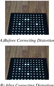
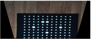
2 can be obtained. Based on the Eq. 3 and the given image coordinates, the distortion can be corrected, as shown in Fig. 1A)Before Correcting Distortion
[image:2.612.367.478.375.553.2]B) After Correcting Distortion
Fig. 1 Comparison Of The Result Images About The Radial Distortion
2.2
COORDINATES TRANSFORMATIONThe navigation information should be founded on the world coordinates, so the coordinate transformations must be taken. The relation between
image coordinates
(
x y
i, i)
and CCD(Charged1817-3195 ( ) ( ) i x i y x c d x x s x y
d y y c
− = −
(5)
where
( ,
c c
x y)
is the center of image coordinates.,
dx dy
are the scale of the camera, in mm per pixel;sx
is the aspect ratio;( ,
c c
x y)
,dx dy
,
,sx
can beobtained from the camera calibration.
As shown in Fig. 2 and Fig. 3, the definition of the camera coordinates are:
1
x
axis is the same as
x
axis;1
y
axis is the same as
y
axis;1
z
axis is aligned with the optical axis;
The center of the coordinates is the center of the pin-hole model;
As all the points in the image are on the ground plane, the equation below exists, as shown in Eq.(6)
1
cos
1sin
0
y
θ
−
z
θ
− =
h
(6)
where h is the height of the camera.
According to the pin-hole model, the following equation also exists, as shown in Eq.(7)
1 1 1
x
y
z
x
=
y
=
f
(7)
[image:3.612.83.523.67.747.2]where f is the focal length of the camera.
[image:3.612.326.520.627.711.2]Fig. 2 Position OF THE CAMERA
Fig. 3 Camera Coordinates, Side View
As shown in Fig. 3, the definition of the world coordinates are:
2
x
-axis is the same as
x
1-axis;2
y
-axis is perpendicular to the ground plane;
2
z
-axis is parallel to the ground plane, it is the projection of the optical axis on the ground plane, as shown in Eq.(8)
2 1
2 1
2 1
1 0 0
0 cos sin
0 sin cos
x x y y z z
θ
θ
θ
θ
= − (8)
According to Eq. 6 and Eq. 8, the following equation exists, as shown in Eq.(9)
2 1 2 1 2 sin co s x x y h z h z θ θ = −
(9)
Based on Eq. 5, Eq. 6, Eq. 7, Eq. 9, the world
coordinates
(
x
w,
z
w)
(equivalent to( ,
x z
2 2)
) which are defined over the ground plane, can be expressed in Fig. 5, the result can be seen that the perspective projection of the target board image has been transformed to the world coordinates, but the errors of the coordinate transformation also exist.1
z
1y
2y
h
Ground planeθ
θ
tilitangle h camera height
2
1817-3195
3. EXPERIMENTS AND DISCUSSIONS
3.1
Images ObtainmentIn order to obtain the improvement of the vision navigation system of field robot, Fig.1. (a) was regarded as a typical image of the target board image acquired in the laboratory of Computer Science School of Inner Mongolia University, using a Chinese microvision digital camera (MV-VD030SC), single lens reflex, 8mm focus. The positioning parameters of the camera were listed, the tilt angle:45 degree; the height of the camera:705mm; the roll angle:90 degree; the yaw angle:90 degree; the distance between the camera and target board:608mm. The white points in the target board image were parallel, which could simulate the structure of crop rows, and their coordinates were obtained by hands, or using the algorithm presented in this paper to improve the performance of the vision navigation of field robot.
3.2
Experiments Based On The Target Board [image:4.612.312.517.75.270.2]In order to test the accuracy and stability of the single camera vision navigation system after the lens distortion correction and coordinates transformation, the target coordinates (white points) on the board placed on the ground were tested in this experiment, as shown in Fig. 1. The coordinate data were collected by using a tapeline from the white points from the 2nd column, 4th column, 6th column, 8th column and 10th column, and then, the corresponding test results using the algorithm presented in this paper were also obtained through inputting the corresponding image coordinates. In order to avoid the interference of the measurement errors, the mean errors from the absolute differences of the actual and tested coordinates corresponding to each column are utilized to evaluate the performance of the algorithm in this paper in terms of x, y axis orientation mean errors and angle error, as shown in Fig. 5.
Fig. 5 Error Comparison Of Coordinates And Angle
Obviously, the mean errors in x, or y orientation are reduced after correcting distortion (as blue line shown in Fig.5.(1), Fig.5(2), respectively), and at the same time, the angle errors also are reduced. However, the error curves are not velvet, especially, the angle errors are also important for the turning of robot field. And the symmetries of the error curves are not good, especially for angle error curve. Because the sixth column is consistent with the optical axis of the camera, those error curves in Fig.5 should have good symmetry about this column. But, the results shown in Fig.5 indicate that the errors may affect the accuracy and stability of the vision navigation system for field robot.
3.3 C
orrectness Of The Navigation Parameters1817-3195
Fig. 6 Error Comparison After Interpolating Using B Spline
[image:5.612.90.313.488.641.2]Obviously, for x axis orientation errors, the error curve is less changed after interpolation using the third-order B spline, as shown in Fig.6.(1). However, the curves of the y axis orientation and angle errors are greatly changed, as shown in Fig.6(2) and Fig.6(3). And their symmetries after interpolation are improved better than before (see the green line in Fig.6.(2) and Fig.6.(3)). Furthermore, as shown in Fig. 7, the tracks of the tested points of each column coincide with the corresponding actual points column, and the errors of x and y axis orientations only millimeter level, the maximal angle mean error only 0.35 degree. And the good performances of the third-order B spline can provide less error control for field robot walking along crop rows.
Fig. 7 Tracking Path Using The Third-Order B Spline Interpolation
4
CONCLUSIONSIn this paper, the typical experiment was designed
using the target board image. And the positioning parameters of the camera were set according to the actual experiences in the field work for the field robot automatically walking along the crop rows. The lens distortion correcting and third-order B spline interpolation are used to improve the performance of the vision navigation system of field robot. The accuracy and stability of the vision navigation system are improved, with the mean errors of x and y axis orientations only millimeter level, the maximal angle mean error is only 0.35 degree. And the proposed algorithm is proved to be effective.
ACKNOWLEDGEMENTS:
The work of this paper has been supported by National Natural Science Foundation of China (Nos. 3116025), Introduced Talents Start-up Fund of Inner Mongolia University (No.209053), College student innovation fund of China (No.111012615).
REFERENCES:
[1] B. Astrand, A.J. Baerveldt, “A vision based row-followingsystem for agricultural field machinery”, Mechatronics, Vol. 15, No. 2, 2005, pp. 251-269.
[2] J. Billingsley, M. Schoenfishch, “The successful development of a vision guidance system for agriculture”, Computers and Electronics in
Agriculture, Vol. 16, No. 2, 1997, pp. 147-163.
[3] G.E. Meyer, J.C. Neto , “Verification of color vegetation indices for automated crop maging applications”, Computers and Electronics in
Agriculture,Vol. 63, No. 2, 2008, pp. 282-293. [4] Wang Jianhua, Shi Fanhuai, Zhang Jing, Liu
Yuncai, “A new calibration model of camera lens distortion”, Pattern Rocognition, Vol. 41, No. 2, 2008, pp. 607-615.
[5] Zhang Guangjun, He Junji, Yang Xianming, “Calibtating camera radial distortion with cross-ratio invariability”, Optics & Laser
Technology. Vol. 35, No. 6, 2003, pp.457-461.
[6] Li Mei Song, Ming Ping Wang, Lu Lu, Huang Jing Huan, “High precision camera calibration in vision measurement”, Optics & Laser Technology, Vol. 39, No. 7 2007, pp. 1413-1420.
1817-3195
[8] J.A. Marchant, Renaud Brivot, “Real-Time Tracking of Plant Rows Using a Hough Transform”, Real-Time Imaging, Vol. 1, No. 5, 1995, pp. 363-371.