\,~ .. j; • . 0<'>;;1\!:;' \ \ ... ~-\ \j -\;-~ \-,4; ":. ..1 'I ~, "''''''~ ~ i '\ i .... ;.
h .• r"t'l...)"
.~'"
...
'".. ~,. • • • io., . . . .
Jr..*~
...
... !l." ... ,."I' . -.
.,.,.• .., . . . 'l'iI'-lII." ...
... ..
...
...
~.* .... ,... •• "... .
. . . . Itt ... • ... •
...
...
,.... .
. . . -.fr. . . . ~ .... ~
~
...
., ... """"""'''''' ~~. 4 ... .., "',. ... ;1. 'I-.j ok • lie . . . ., i
• ""lIe ... ~. 'I- . . . "i flo,., . " . . . , ,.,''If'" * •• ~
,,"' ... !
'9-il' . . . " . . . " ' . " . ;
"' . . . '% . . . '
.. '''' ... ' ... ,..* •. !
.• ... ' ... ·.1
...
"' .... .....
.
... "... ...
"'-...
.
.""~...
"'....
""...
'"...
~ "' . . . - . . ' I ' . . :J_.: •• ' •••••• '4 ... --... ~.. ... • • •
~ ~·:t~~:;2~:~~~:~~?::::::::::::::::'
DEC
COMMUNICA TIONS
EQUIPMENT
DEC
CONTENTS
CHAPTER 1 INTRODUCTION
DEC's Communication System Design Approach
Data Communication System Design Factors
Low-Speed Serial Asynchronous Communications
Type of Terminal
Low-Speed Terminal Characteristics
Transmission Media
Parallel Devices
Medium -Speed Communication
Medium-Speed Terminal Characteristics
High-Speed Communications
High-Speed Terminal Characteristics
Summary of DEC Communication Equipment Characteristics
CHAPTER 2
APPLICATIONS OF DEC COMMUNICATION EQUIPMENT
PT08 Serial Line Interface
680 Data Communication System
OPOl A Synchronous Modem Interface
Asynchronous Data Communication Channel Type 636
DP02A/DP03 Automatic Dialing Equipment
Parallel Data Channels
Interprocessor Buffers
Parallel Devices
Communication System Examples
A irl i ne Reservation and Management System
Time-shared Computer Service
Multi-Terminal Data Processor
Centrally Monitored Process Control Sites
Special Communication System Requirements
1-1
1-1
1-2
1-3
1-3
1-4
1-5
1-5
1-5
1-6
1-6
1-7
2-1
2-3
2-7
2-8
2-9
2-10
2-10
2-11
2-11
2-12
2-13
2-14
2-15
CONTENTS (Cont)
CHAPTER 3
DEC SERIAL DATA COMMUNICATION EQUIPMENT PERFORMANCE AND INTERFACE CHARACTERISTICS
PT08 Asynchronous Serial Line Interface
Principles of Operation
Character Format
Speed
Programming
lOT Instructions
Maintaining Maximum Data Rates
Interfacing to Teletype Equipment
Input Data
Reader Run Signal
Output Data
Cabling
Interfacing to EIA Devices (PT08F Option)
Data Signal Polarity
Cabling
680 Data Communi cation System
Principles of Operation
Character Structure and Data Rates
Data Rate Versus Number of Lines
W750 Serial Line Unit
680 System Software and Programm i ng
5-Bit and 8-Bit Character Assembly Routines
Diagnostics
Interfacing to the 680
Direct Interfacing to 685 Serial Line Multiplexer
Type 682 Loca I Line Pane I
Input Characteristics
Output Characteristics
Spec ial Features
Cabling
iv
.Page
3-1
3-1
3-1
3-1
3-2
3-2
3-3
3-4
3-4
3-4
3-4
3-4
3-4
3-6
3-6
3-7
3-7
3-8
3-9
3-9
3-10
3-11
3-11
3-12
3-12
3-14
3-14
3-15
3-15
CONTENTS (Cont)
Telegraph Interface Equipment (683, 688, 687, 791)
G852 Telegraph line Adapter Module
Output to Telegraph line
687 line Monitor Panel and 688 Telegraph Line Panel
791 and 635A Power Suppl ies
Type 689 Data Set Interface Equipment
689-MP Modem Interface Panel
689-MIA Modem Interface Adapter
689-ADF Modem Interface with Additional Features
689-MIC Modem Interface and Control Features
689-ACU Automatic Dial -Out Features
Installation
Type DPOl A Synchronous Data Communication Channel
Principles of Operation
Sync Characters
Data Format
Starting Transmission
Maintaining Transmit Data Stream
Transmit Active/Transmit Idle Modes
Assembling Received Data
Clear Receive Active
XOR Option
lOT Commands
E IA Interface
Request to Send
T ransm i tted Data
local Timing
Data Terminal Ready
Serial Clock Transmit
Serial Clock Receive
Data Set Ready
3-15
3-17
3-18
3-19
3-19
3-19
3-19
3-20
3-20
3-22
3-23
3-25
3-27
3-27
3-28
3-28
3-28
3-28
3-29
3-29
3-29
3-29
3-29
3-30
3-31
3-31
3-31
3-31
3-31
3-31
CONTENTS (Cont)
Received Data
Ring Indicator
Insta Ilation
Type 636 Asynchronous Data Communication Channel
Principles of Operation
Data Transfer
Data Set Control
Character Codes and Speeds
EIA Interface
Transmitted Data
Data Terminal Ready
EOT Detected
Receive Data
C lear to Send
Ringing Indicator
Restra i nt Detected
lOT Commands
Skip if Data Transmit Flag Not Set (SOT)
Clear Data Transmit Flag (CTF)
Transm it a Character (T AC)
Skip on Receive Flag Not Set (SDR)
Skip if Clear to Send (SCS)
Clear Receive Flag (CRF)
Read a Character (RAC)
Skip if Restraint Not Detected (SRD)
Set Terminal Ready (STR)
Clear Terminal Ready (CTR)
Set End of Transmission (SET)
Programm i ng
Installation
DP02A/DP03 Automatic Dialing Equipment
vi
3-31
3-31
3-32
3-32
3-33
3-33
3-33
3-33
3-33
3-34
3-34
3-34
3-34
3-34
3-34
3-36
3-36
3-36
3-36
3-36
3-36
3-36
3-36
3-36
3-37
3-37
3-37
3-37
3-37
3-37
CONTENTS (Cont)
CHAPTER 4 EXAMPLE OF DEC
PARALLEL INTERPROCESSOR INTERFACE
DM03 Data Channel
1-1
1-2
1-31-4
2-1
2-2 2-32-4
2-5
2-62-7
2-82-9
2-10 2-11 2-12 3-1 3-2 3-3 InterconnectionsPrinciples of Operation
Programm i ng
APPENDIX A
COMMUNICATION MODULE SCHEMATICS
ILLUSTRATIONS
Adapting Low-Speed Asynchronous Terminals to a Computer
Telegraph and Modulated-Carrier Transmission of Low-Speed Data
Medium-Speed Communication Link Through Dial Telephone Network
Types of DEC Communication Equipment
PT08 Equipment Configurations
Typical PT08 Applications
Cost per Channel - PT08 vs 680 Systems
680 System Equipment Configuration
Typical 680 System Applications
DPOl A Equipment Configurations
Typical 636 System Installations
DP02A/DP03 ACU Control Equipment Configurations
Communication Equipment in Commercial Data Processing and Control Network
Communication Equipment in Computer Time-Sharing Appl ications
Communication Equipment in Large - Scale Data Processor
Communication Equipment in Multiprocessor System for Process Control
Typical PTOS. System Cabling Diagram
PT08 Program Response Time
PT08 Teletype Interface
3-4 3-5 3-6 3-7 3-8 3-9 3-10 3-11 3-12 3-13 3-14 3-15 3-16 3-17 3-18 3-19 3-20 3-21 3-22 4-1 1-1 1-2 2-1 2-2 2-3 2-4 3-1 3-2 3-3
CONTENTS (Cont)
ILLUSTRATIONS (Cont)
PT08F Data Set Interface
680 System Functional Block Diagram
680 Processor Loading
W750 Simpl ified Logic Diagram
Typical 680 System Cabling Diagram
W750 Output Circuit Simplified Schematic
W750 Input Circuit Simplified Schematic
Typical Connection Type 682 Local Line Panel
680 System Tel egraph Li ne Interfaci ng
G852 Module Simplified Schematic
689-MP and 689-MIA Modem Interface
689-ADF Modem Interface with Additional Features
680 Communication System Cabinet Arrangement
Typical 680 System Option Installations
DPOl A Synchronous Data Channel
DPOl A Data Set Interface
636 Asynchronous Data Communication Channel Character Format
636 Data Set Interface
DP02A/DP03 ACU interface
DM03 Data Channel
TABLES
Low-Speed Communications Terminals
Comparison of DEC Communication Equipment Features
PT08 Serial Line Interface, Summary of Specifications
680 Data Communications System Summary of Specifications
DPOl A Synchronous Modem Interface Summary of Specifications
636 Data Communication System Summary of Specifications
Modems Compatible with PT08F Interface
689-MIC Control Line Functions
689-ACU Control Line Functions
FOREWORD
This manual provides general information, application examples, detailed specifications,
and ordering data for Data Communication Equipment manufactured by Digital Equipment Corporation
(DEC).
"Data Communications Equipment" is equipment for the exchange of digital data, usually in
serial form, between geographically remote digital equipment installations, at essentially
conversa-tional speeds.
DEC·s data communications equipment is intended primarily for low and medium speed
asynch-ronous and high-speed synchasynch-ronous, transmissions over serial communication lines, either common
car-rier or privately owned. In addition, special-purpose parallel channel s are available for intercomputer
and computer-to-peripheral device data exchanges.
Data communication techniques, characteristics of widely used communication channels, and
a summary of available commercial communication facilities, are described in a companion document,
"Introduction to Data Communication, II also published by Digital Equipment Corporation. Copies are
available on request. Also recommended to supplement this manual are DEC·s Small Computer Handbook
CHAPTER 1
INTRODUCTION
DEC'S COMMUNICA liON SYSTEM DESIGN APPROACH
In the past six ye(1rs, DEC has supplied communication equipment for a variety of industrial,
scientific, military/aerospace, and commercial data communication systems. These installations range
from a few remote keyboard/printers to complete multi-station message storing, forwarding, and
switch-ing systems involvswitch-ing hundreds of data channels. Some of the special system types developed and
in-stalled during this time include:
Message switching, storing, and forwarding systems
Communication controllers for large data processors
Message concentrators
Message switching network supervisory systems
Communication line control for time sharing systems
Management information systems
In the course of this hardware experience, DEC has developed a standard product line which
allows PDP computers to exchange data with the most common communication devices and facilities.
DEC's communication products combine the data handling flexibility of the low -cost general
purpose PDP Family-of-Eight computers with specialized hardware to interface with standard
communi-cation devices and communicommuni-cation medi a.
For small numbers of lines, the systems rely on special -purpose hardware for data buffering
and assembly, leaving most of the computer time free for other functions.
Larger systems use the PDP-8 computer as the central logic element, in place of duplicated
wired logic units. This programmed-logic approach reduces the hardware cost per line and provides
much greater flexibility in system expansion and design modification. DEC supplies the basic
opera-tional and maintenance software.
Small and large systems alike are simplified by solid state functional logic modules for con
-trol and interfacing to a variety of terminals and transmission media. Modular system expansion on a
per-line basis ensures a low per-channel cost and simple system expansion.
DA TA COMMUNICATION SYSTEM DESIGN FACTORS
The design of a serial data communication system for a particular task involves a number of
variables, such as:
Speed
Transmi ssion distance
Coding Technique and format
Synchronous channel s:
Mode of operation (half or full duplex)
Bi ts per character
Synch character code
Communication medium (private, leased or public transmission lines: DC or
modulated communication technique; data set control features)
Number of channels operciHng simultaneously
Many of these topics are di scussed in detai I in a companion documen t, "Introducti on to Data
Communication," also published by DEC and available on request. The manual covers: the principles
of serial data transmission; types of terminals and data links; Teletype, telegraph and modulated
trans-mission data links; and the public facilities available for transmitting serial data over long distances
(i.e., Dataphone Service, Wide Area Telephone Service, Teleprinter Exchange Service (TWX), etc.).
The following paragraphs provide more detail on important design factors involved in
adapt-ing such data communication channel s to a digital computer. For convenience, the applications are
classified according to speed: low (0 to 300 baud), medium (1200 to 5000 baud) and high (4800 to
200,000 baud). Low speed devices encompass the widely used serial asynchronous terminal devices,
which usually permit a conversational interchange of data among many stations at essentially manue"
speeds. Medium and high-speed applications are usually under automatic computer control at both the
sending and receiving terminals. The data can be converted to low-speed form and distributed to
conversational terminals through the computer.
Low - Speed Serial Asynchronous Communications
Perhaps the most common, and simplest, data communication application is where extra
asynchronous character devices, such as keyboard/printers or tape reader/punch units, are added to a
computer's peripheral equipment complement. (See Figure 1-1.) The interface equipment is controlled
from the computer's I/O bus, converting parallel computer words to asynchronous serial characters, and
the reverse.
Low-speed communication equipment usually handles data at a manual rate. Some typical
applications in this inherently low -speed environment are:
a. Time -sharing, conversational type terminal s, such as Teletypes
b. Message storing, switching, and forwarding systems
c. Airl ine reservation systems
d. Information retrieva I systems
_.---_ _ _ _ ---+ OTHER PERIPHERALS
Figure 1-1 Adapting Low -Speed Asynchronous Terminals to a Computer
Type of Terminal - A typical low -speed terminal is the Teletype keyboard/printer. With optional
paper tape reader and punch, an ASR or KSR Teletype is an economical source of most low-speed
com-puter input/output requirements. These units are commercially available at low cost, and have a good
service and maintenance hi story. Because the serial asynchronous character code is readi Iy transmi tted
over commercial transmission lines, it has become a common communication medium even when keyboard,
paper tape, or other standard character devices are not directly involved. For example, in situations
where high data rates are not required, an asynchronous data link is the most economical intercomputer
communication method.
Tabl e 1-1 lists typical low -speed communi cation terminal equipment.
Table 1-1
Low-Speed Communications Terminals
Characters
Manufac turer Model Speed Per Second
Teletype 28 50 baud 0-7
Teletype 32 75 baud 0-7
Teletype 33 110 baud 0-10
Teletype 35 110 baud 0-10
Teletype 37 150 baud 0-15
Teletype Telespeed 110 baud 0-10
Siemens 100 50/75 baud 0-7
IBM 1050 134.4 baud 0-15
Kleinschmidt 311 150/300 baud 0-30
Friden 150 baud 0-15
Low - Speed Terminal Characteri sti cs - Typical characteri stics of low -speed terminal equipment are:
Speed
Format
Bit serial asynchronous
1 start bi t
5, 7, or 8 data bits
1, 1.5, or 2 un i t stop bi ts
Communication Media
Customer installed private wire
Common carrier installed wires*
Common carrier installed modems via common carrier supplied wire
Transmission Media - The final medium for transmitting the data between stations depends upon the
distances involved and the choice of privately installed or common carrier lines.
For a system with remote keyboard terminals at various sites within a single building or group
of bui Idings, privately installed I ines using low -vol tage dc current keying are common. Most serial
asynchronous terminals can operate on such lines at distances up to 1500
ft,
depending on the electricalenvironment. For greater distances, high-voltage telegraph-type keying or the use of an asynchro··
nous modem (data set) is more reliable. (See Figure 1-2.)
COMPUTER
1/0 BUS
- - I r - - --..,
I AUTOMATIC I - - ' ASYNCHRONOUS I r - - - - _ .., r _ _ _ _ _ ..,
:
CAuL~I~NG
1 - :---.,;·L -
~r~
-
J ____
._--+_~
,-_+-,-,,:
~~~~~:~I~~ ~ T~~~~~!L
I
L - - - .J L _ E~I~M~N!..
J
L _ _ ___J
TRANSMISSION
UNE r - - - .., r - - - ,
~--I---.I ASYNCHRONOUS I I REMOTE I
: MODEM
n
TERMINAL lL _ _ _ _ _ .J L _ _ _ _ _ .J
Figure 1-2 Telegraph and Modulated -Carrier Transmission of Low - Speed Data
* Common carriers limit the data rate on leased lines with dc current keying to 75 baud. To exceed 75 baud, modems are required.
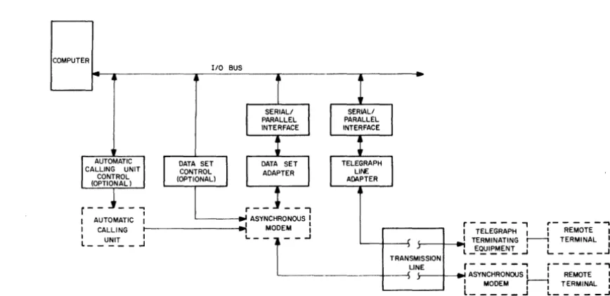
[image:15.618.76.510.382.593.2]Asynchronous modems (such as Dataphone) may be used for full-duplex data transfer on
pri-vate lines without any special provisions for control of the data set. However, for operation over a
common carrier, some automatic control features for the data set are usually desirable. (The controls
confirm that the local and remote modems are in synchronization, etc.) Data set control requirements
are more stringent when operating through the standard dial telephone network; an automatic answering
feature is usually needed to acknowledge that the local set is receiving an incoming call. Automatic
calling control may also be necessary to permit the computer program to initiate outgoing calls without
operator intervention.
DEC's communication equipment is designed so that a basic asynchronous interface can be
easi Iy adapted for operation on any of the common communication media.
Parallel Devices - In almost all low -speed, remote-terminal applications, the communication channel
is serial asynchronous. However, some low-speed parallel devices, such as credit card and employee
badge readers, are now coming into general use. Such equipment is most easily interfaced to a DEC
system by a simple para" el interface operated through the computer input/output bus. The computer can
reformat the data and enter it into the serial data lines under program control. Because such devices are
not yet standardized, DEC does not offer standard product-line interfaces, but, parallel devices can
usually be accommodated on a special system basis.
Medium - Speed Communication
Medium speed communication channel s are commonly used to adapt a computer to a single
serial transmission line, usually through a modem. The computer serves as an intermediary for data
from any item of peripheral equipment, serial or parallel. Typical applications are
computer-to-computer data transfer, or communication between a computer-to-computer and a high -speed electromechanical
de-vice. Another growing area of application is communication with character and graphic display
terminals.
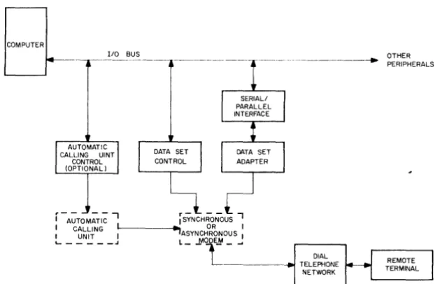
Data from several low -speed asynchronous channels can be assembled by the computer and
transmitted over the channel at a higher rate. With the computer performing bit rate conversion,
character formatting and data set control, such a channel can set up communication between a number
of low-speed lines and any station in the dial telephone network. (See Figure 1-3.)
Medium - Speed Terminal Characteristics - Typical characteristics of medium -speed terminal s are:
Speed
1200 to 5000 baud
Format
8 bits serial, synchronous or asynchronous.
Buffered devices, such as displays are usually synchronous. Unbuffered devices, such as
Commun ication Medi a
Privately owned modems on leased or private lines
Common carrier supplied modems on common carrier supplied lines
DIAL
TELEPHONE NETWORK
Figure 1-3 Medium-Speed Communication Link Through Dial Telephone Network
High - Speed Communi cations
For fast response time and high data volume, communication through a high -speed
synchro-nous modem is the usual sol ution. In general, such channel s are used for the same purposes as medi
um-speed equipment -- for interprocessor communication, transfer of high -um-speed peripheral equipment data,
or as a common transmission line for many channels of low-speed asynchronous character data.
These facilities are expensive so they are used only when necessary. Channels with up to
million baud capacity are available in some areas of the country, but these are handled as special
engineering projects by the common carrier servicing that area; as much as 18 months can elapse from order to installation.
High - Speed Terminal Characteristics - Typical characteristics of hi gh -speed terminal s are:
Speed
4800
to200,000
baudFormat
6- to 9-bit synchronous {efforts at standardization are underway in the industry}.
[image:17.618.149.460.137.340.2]Communication Media
Common carrier supplied modems and channels.
Privately owned microwave links.
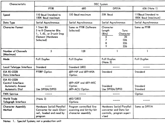
SUMMARY OF DEC COMMUNICATION EQUIPMENT CHARACTERISTICS
Figure 1-4 shows the types of communication equipment that can be interfaced to a PDP
Family-of-Eight computer. Table 1-2 summarizes the interface options and performance characteristics
of DEC serial communication channels.
DEC supplies four basic serial data communications systems plus an automatic dial-out
device.
The PT08 Asynchronous Serial Line Interface provides full-duplex communication between
serial asynchronous devices or transmission lines and the PDP-8 Computer. The system expands up to
five channels, in a modular fashion. Typical operation is at 110 baud, but the system can be ordered
for speeds up to lOOK baud. The basic data channel matches 20-mA dc -keyed local devices (Teletype,
etc.). An optional data set interface permits operation through an asynchronous modem such as Bell
Data Set tv\odel 1 03A.
;-~~~~~RP~ ; J
I
r---.
INTER It
PARALLEL
,
PARALLEL II LARGE DATA
l
PROCESSOR INTERFACE .. DATA 14--- PARALLEL DATA CHANNELSL !:.RQ..C~S2R_ I BUFFER (SPECIAL ORDER) L _____ .J
:
t
I
PDP FAMILY- OF - EIGHT COMPUTERI
:
:
:
I
636
I 1
680 SYSTEM 1 I
DP01A I
I DP02AI I DP03
I
PT08 I+-SERIAL DATA CHANNELS
~ ~
r
5,..---NO. OF CHANNELS (MAX)I I 128 128 8 128
,
4 5I I 0 J TTY
r
500' MAXJ LOCALI
DATA I 1 0 ] CONVERSION
I
l
TERMINALI KIT
.. ---~
DATA AND CONTROL 2400' TO 4800 I
SYNCHRONOUS I
-,
MODEM I... --r--
JCONTROL
_-_L--
1CONTROL AUTO
--- CALLING I
CONTROL -"" UNIT I
'--1---DATA ONLY 110
.,--.1---DATA ONLY OR .,--.1---DATA AND CONTROL 110 IIoIA SYNCHRONOUS'
DATA a CONTROL 110 MODEM I
t - - - ~ -
- -
-
__
,
r---·
DATA a CONTROL IA SYNCHRONOUS:
I MODEM I
TYPICAL l(!~X __ ~t!,(!<2.E.l!
OPERATING SPEEDS(BAUD)
WORLD
DATA 75
TRADE
[image:18.617.91.553.338.682.2]I
(X)
Table 1-2
Comparison of DEC Communication Equipment Features
Charac ter i stic DEC System
PTOS 680 DP01A
Speed 110 Baud Standard to 150 Baud maximum 50K Baud lOOK Baud maximum
Data Type Serial Asynchronous Serial Asynchronous Serial Asynchronous
Character Format 1 Start Bit Same as PTOS (Software Character
5 to 8 Charac ter Bi ts Selected) Length Sync
1, 1.42, or 2-unit Stop (Bits) Character
Element (Hardware 6 26
Selected) 7 026
8 226
9 226
Number of Channels 5 128 1
(Maximum)
Mode Full Duplex Full Duplex Full Duplex
(Note 2)
Local Teletype Interface Standard Standard (682)
---EIA RS-232B PTOSF Option 689-NP and 689-MIA Standard
Data Interface Option
EIA RS-232B
Control Interface: 689-ADF and 689-MIC
Automatic Answer
---
Option StandardAutomatic Dial Use DP02A/DP03 689-ACU Option Use DP02A/DP03
TWX Service
---
------World Trade (Note 3) 683/G852
---Telegraph Interface Options
Character Assembly Hardware Ser i a I/Para II e I Program controlled line Hardware Serial/Parallel Method Converter for each Chan- scanning and bit-by-bit converter and Data Set
nel, loaded and read by character assembly controls, program
super-program vised
Notes: 1. Special System; not a production unit
2. Half-Duplex Operation optional 3. Available on Spec ial Request
636 (Note 1)
110Baud Standard to 180K Baud (maximum)
Serial Asynchronous
Same as PTOS
1
Full Duplex
---Standard
Standard Standard
Option
[image:19.794.139.686.109.519.2]
The 680 Data Communication System has as its central controlling element a PDP-8 Computer,
which is programmed to handle character assembly, both on input and output, for up to 128 serial
asynchronous lines. Programs are supplied to handle data rates of 50, 75, or 110 baud and 5- or
8 -bit character codes. Interfacing equipment may be added to the basic system for operation on 20 -mA
dc -keyed local lines, polar or neutral Telegraph lines, or through asynchronous modems such as Bell
Data Set f.Aodel 103A. Additional control equipment is available for automatic answering and dial -out
through the data set.
The Type DP01A Synchronous Data Communication Channel is an interface between the
PDP-8 Computer and a synchronous modem such as Bell Data Set f.Aodei 201 B. Typical data rate for
the DP01A is 2400 baud; the system operates at rates up to 40,800 baud.
The Type 636 Asynchronous Data Communication Channel is an interface between the PDP-8
Computer and an asynchronous modem such as Bell Data Set Model 1 03A. Th i s equi pment permi ts
asynchronous operation at speeds up to 250K baud. Automatic data set control, answering, and
dial-out are standard features.
The DP02A/DP03 Automatic Dial ing Equipment enables a PDP-8 Computer to control up to
four Bell f.Aodei 801 Automatic Calling Units (or equivalent). The automatic calling units may be used
CHAPTER 2
APPLICATIONS OF DEC COMMUNICATION EQUIPMENT
This section summarizes the operational characteristics of DEC·s standard data communication
equipment. These systems can be used alone or in modular combinations to form versatile communication
systems. Applications examples at the end of this section illustrate typical modular system designs.
PT08 SERIAL
LI
NE INTERFACEDEC·s PT08 system and the options available with it represent the type of system in which
hardware in the interface performs character synchronizing and assembly. Computer time is
re-quired only when characters or words are ready to be transmitted and received, on an interrupt basis.
Most of the computer·s time is available for a real-time task or computation. Even at the maximum
traffic rate, PT08 equipment requires less than 0.01 % of the avai lable computer time per channel.
PT08 configurations are favored when data communication is a secondary function of a computer with a
major computing or on -line assignment such as data acquisition.
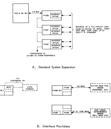
The PT08 series of equipment is economical when 1 to 5 lines operating at rates up to 110
baud are to be interfaced to a PDP-8 computer. The basic system configurations are shown in Figure2-1,
and some application examples are shown in Figure 2-2. Systems expand in a modular fashion up to a
maximum of 5 channels. PT08B provides an interface to the PDP-8 I/O bus, plus one duplex start-stop
serial channel. PT08C units handle two duplex start-stop serial channels each. Performance
specifica-tions are summarized in Table 2-1 •
Characteri stic
Speed
Character Format
Operati ng Mode
Interface
Transmission Distance
Table 2-1
PT08 Serial Line Interface, Summary of Specifications
Specifications
110 baud is standard; up to
lOOK
baud (software limited) with PT08X option.Standard: 8 character bits; 2 unit stop element
PT08X option: 5 to 7 character bits, 1 or 1.42 unit stop element at request of customer.
Full - duplex
Standard: 20-mA de switching for communication with local terminals such as Teletype Model 33, 35 or equivalent.
PT08F option: Provides interface that conforms to EIA R5-232B devices.
1500 ft maximum (environment dependent) for local terminals.
PTOS equipment directly interfaces to full-duplex serial asynchronous devices using 20 rnA dc
keying over
I
ines up to 1500 ft. PT08F adapters can convert any channel for interfacing to EIA R5-232B (Dataphone or equivalent) data links, for longer transmissions. Another option, the PT08X, can beinstalled in any channel for customer selection of character format and speed.
With the PT08F and PT08X options combined, the bit rate can be increased to
lOOK
baud fordriving medium - to high -speed asynchronous modems. This combination can be used for an economical
intercomputer communication channel or interfacing to special equipment with unique asynchronous
speeds and character formats.
PDP-S OR S/I
-
1/0 BUS_,...---
~PTOSB • INTERFACE L~~I~
·
__-
r----' - - - • INTERFACE
..
• OPTIONPTOSC
L... _ _ _ _ _
I INTERFACE
·
- 1
OPTION
' - - I INTERFACE
...
·
I OPTIONPTOSC jiNi-ERFACE- _ -""
r
I OPTION~
CONTINUATION OF
IIO BUS TO OTHER PERIPHERALS
A. Standard System Expansion
TTY
CONVERSION KIT
~
. - - - . - 1 -W-0-1O--o
r - -
L~C:L--i
PTOSB OR C L_ - - - :... _T':~~N~L _J
r----:
t PTOSF _ PTOSB OR C L - -
-
r----I
I
L ____ _
MAXIMUM OF 5 FULL-DUPLEX LINES (20MA DC KEYING OF SERIAL START-STOP CODE OVER LINES UP TO 1500 FT. IS STANDARD)
r - - - ,
100 BAUD lElA RS-232B TYPE • ... MODEM • I (DATAPHONE, ETCJ I
L _______ -l
r -
HiGH ..:-s pi Ei> - ...,.- - - - ., JiPT-O-SF-- jlP TO 1001( BAUD I ASYNCHRONOUS •
PTOSF I ~ MODEM I
I (BELL 2020, ETC,) I
L _ _ _ _ _ _ _ -J
B. Interface Provisions
Figure 2-1 PT08 Equipment Configurations
[image:23.620.130.502.210.643.2]PDP COMPUTER
PDP COMPUTER
PDP COMPUTER
UP TO 1500' (SAME BUILDING) ASR-33 OR OTHER
START -STOP CHARACTER DEV I CE
A. Local Terminal Connection
PRIVATE LINE, LEASED LINE, OR DIAL TELEPHONE NETWORK
B. Remote Terminal Connection
PRIVATE LINE, LEASED LINE, OR DIAL TELEPHONE NETWORK
r---,
1 DATA 1
I SET I
L __ ...J
DATAPHONE TELETYPE TERMINAL
r -;;E;:-L - -'~r ~~L--'
2020 2020
t!~A
-=:2"
J t!~~S.:..r JC. Intercomputer Communication
Figure 2-2 Typical PT08 Applications
680 DATA COMMUNICATION SYSTEM
PDP COMPUTER
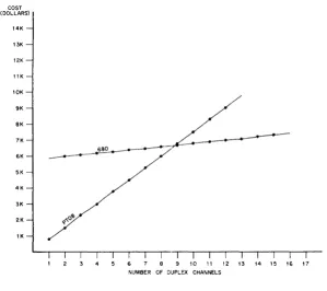
Communication lines connected to PT08 channels require a minimum of program attention
from the computer. However, the cost increases at a nearly I inear rate as the number of channels in a
system increases. A more economi cal approach for mul ti -channel systems is provided by spec ial
equip-ment that scans each channel automatically and assembles characters bit -by -bit in computer memory
locations rather than in hardware shift registers. This approach is provided by the 680 Data
Communi-cation System, which uses a minimum of hardware; instead, the data processing ability of the computer
is utilized for character assembly and control. The hardware cost saving, plus the flexibility of a
soft-ware-controlled system, makes the computer-based system attractive in applications where message
handling is the primary mission of the equipment. An economic crossover in favor of the 680, compared
[image:24.612.158.533.64.502.2]COST (DOLLARS)
14K
13K
12K
11K
10K
9K
8K
7K
---680 6K
5K
4K
3K
2K ~ .... O'b
I K
4 7 9 10 I I 12 13 14 15 16 17
NUMBER OF DUPLEX CHANNELS
Figure 2-3 Cost per Channel - PT08 vs 680 Systems
While a large proportion of PDP-8 computing time is used for character assembly, most'
practical systems leave a significant amount of processor time available for task-oriented message
switching, formatting data, validity checks, editing, error detection, or time -shared functions such as
management information, reservations, or desk calculator use. For example, 32 to 40 channels
operat-ing at 150 baud require about 85% of the computer's capacity, while 128 channels at 50 baud require
only 60% of capacity.
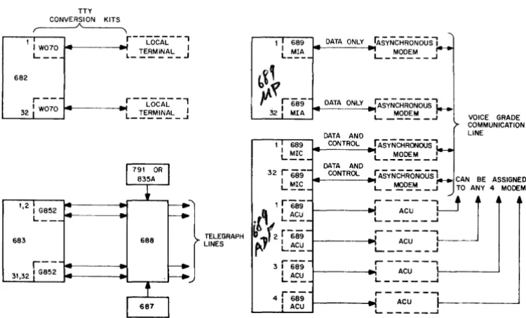
The 680 system can be expanded in a modular line by line fashion to fit a variety of appli
-cations. (See Figure 2-4.) All 680 systems include the PDP-8 computer, 681 Serial Line
Adapter, and 685 Serial Line Multiplexer. Together these units form a basic 680 system with provisions
for handling up to 128 full -duplex serial asynchronous devices. Different types of device or
communi-cation line are accommodated by additional interfacing options.
Type 682 Local Line Panel permits connection of up to 32 local terminals employing 20 rnA
dc keying (Teletype, etc.). The 682 drives local lines up to 1500 ft long. Teletype Conversion Kits
are available as a convenient means to plug in Teletype or similar terminals. For longer lines, modem
interface equipment or telegraph line interface equipment is required.
Type 689 modem interface equipment comes in two configurations; one provides control of the
modems whi Ie the other does not.
[image:25.615.150.450.56.323.2]TTY CONVERSION KITS
~
1 I W070
L __
682
1,2 I G852
L __
683
r--31,32 I G852PDP-8
r
-~ 681
CONTINUATION OF
.~
[
---110 BUS TO OTHER 4
-PERIPHERAL DEVICES
---685
A. Basic System
688
}
TELEGRAPH LINES
I 689 I MIA
L __ _
3 r689
L~~
4 r689
I ACU
B. Interface Options I INTERFACE OPTION 32 33 INTERFACE OPTION 64 65 INTERFACE OPTION 96 97 INTERFACE OPTION 128
DATA ONLY IASYNCHRONousl L _ ~~D~M __ .J
DATA AND
VOICE GRADE COMMUNICATION LINE
CONT~ASYNCHRONOUSJ.-CAN BE ASSIGNED
L _ ~D!~ _ .J TO ANY 4 MODEMS
r---u~
---I L _ _ _ _ _ ACU ....I I
.---,
----.I L.. _ _ _ _ _ ACU ..J :
-r- - - ,
- - . . : L. _ _ _ _ _ ... ACU I
r - - - ,
ACU ~--______ ....I
L.. _ _ _ _ _ - I
[image:26.615.136.511.319.546.2]689-MP Modem Interface Panel accommodates up to 32 Type 689-MIA Modem Interface
Adapters. Each 689-MIA unit serves as an interface between one data channel of the 685 and a serial
asynchronous modem conforming to EIA Standard R5-232B (Dataphone or equivalent). The modem
con-tro line ("request to send, II etc.) must be set up manually or by separate equipment.
The 689-ADF Modem Interface with Additional Features also exchanges data with up to 32
asynchronous modems, through one 689-MIC {Modem Interface and Control} per data channel. Each
689-MIC includes programmed control of the modem for automatic control. In addition, the 689-ADF
incl udes provisions for up to four 689 -ACU Auto Dial Out Features. Each 689-ACU permits the
com-puter to control an Automatic Calling Unit (Be" 801 or equivalent) for program-controlled dialing of
any number in the dial telephone network. The ACU channels can be assigned to provide automatic
dial-out for any of the data lines.
World trade telegraph lines, or equivalent, are matched by the 683 Telegraph Interface
Panel, 688 Telegraph Line Panel, 687 Line Monitor Panel, and 791 or 635A Power Supply.
These options permit a modular system bui Idup for efficient handling of any combination of
local dc keying terminals, modem data links, or telegraph lines. All interface options are expandable
on a line-by-line basis. Interconnections to local terminals are through W070 plug-in modules. (The
Teletype Conversion Kit is a W070 with the cabling installed and terminals at the other end for direct
connection to a Model 33 Teletype or equivalent. The conversion kit is supplied for Teletype units
supplied by DEC with the system.) Telegraph lines are accommodated by the G852 Dual Telegraph
Lev-el Converter module. (Each G852 handles two full -duplex lines.) Type 689 equipment for mc)dem
interfacing employs one 689-MIA or 689 -MIC per active channel. In addition, up to four 689-ACU
Auto Dial Out features may
be
installed in a 689-ADF.Programs for the basic data assembly functions are supplied with each system. These may be
modified, if necessary, for special applications, and other programmed functions may be added. Fu"
software control over the details of character assembly, synchronization, and formatting produces
max-imum flexibil ity and ease of expansion. Performance specifications are summarized in Table 2-2.
Typical applications are shown in Figure 2-5.
Table 2-2
680 Data Communication System Summary of Specifications
Characteri sti c
Speed
Character Format
Operating fv40de
Number of Channels
Specifications
o
to 150 baud5-, 7-, or 8 -level code (supported by DEC software)
Full duplex (half-duplex operation available)
128 full duplex; expansion of a system is modular on a per -line basis
Table 2-2 (cont)
680 Data Communication System Summary of Specifications
Characteristic
Interface
Transmission Distance
685
PDP - 8
685
Spec ifications
20 mA dc switching for local connection to Teletype Model 33, 35 or equivalent
20 to 60 mA polar or neutral World Trade Telegraph Lines (with 683, 687, 688 options)
RS-232 interface devices for Dataphone service (689 option with Automatic Answering or Automatic Calling Unit features)
1500 ft for local terminals
Built-in adjustments permit operation over several miles of dc-keyed telegraph wire lines.
EIA RS-232B interface: 25-ft cable supplied. Distance beyond data set limited only by communication medium.
682
687 688 683 791
TWISTED PAIR UP TO 1500 FT
TELEGRAPH LINES·"
ASR-33 •
ASR - 28
VOICE FREQUENCY LINES
---..,
r---"'H2
I EI:3:~ - I I EI2A3-2~S-I
I DATA SETI I DATA SET I ASR-33*
---~ ~---~
*ANY SERIAL ASYNCHRONOUS DEVICE UP TO 150 BAND MAY BE US ED.
·"COMMON CARRIERS LIMIT THE USE OF TELEGRAPH FACILITIES TO 75 BAND
Figure 2-5 Typical 680 System Applications
DP01A SYNCHRONOUS MODEM INTERFACE
Both the PT08 and 680 systems are intended for asynchronous operation at relatively low
speeds (typically 50 or 110 baud). Synchronous operation at the 2000, 2400, and 40,800 baud speeds
typical of synchronous data sets or modems, requires the DP01A option to the PDP-8 computer. The
DP01A provides a single ful I -duplex synchronous channel between the PDP-8 and an EIA standard
RS-232B data set. Synchronous serial modems are preferred for medium and high speed communications,
both for improved reliability and higher data rates. DP01A is a single-channel device intended for
Alone it can serve as an interprocessor communication channel between any two stations in the dial
telephone network. With PTOS equipment or a 680 system acting as a message concentrator, the DP01A
can serve as a single economical high -speed communication channel for many low -speed asynchronous
lines. Data set control under program supervision is included as a standard feature, and an ADOl
Auto-matic Calling Unit control can
be
added. Specifications are summarized in Table 2-3.Characteri sti c
Type of Channel
Interface
Interface Connector
Speed
Technique
Character Length
110 BUS PDP-8 OR 811
DP01A
-CONTINUATION OF I/O BUS TO OTHER PERIPHERALS
r---..,
~~r:T~1
I
l
(
SYNCHRONOUS :
MODEM I
_ _ _ _ _ _ -J
BELL 20 OR EQUIVALENT)
Figure 2-6 DP01A Equipment Configurations
Table 2-3
o
POl A Synchronous Modem Interface Summary of SpecificationsSpecifications
Half- or Full -Duplex
EIA RS-232B (Other synchronous modem interface specifications avai lable upon request)
Cinch or Eznnon DB-19604-432 with hood
Up to 50,000 baud
Synchronous serial
Sync code is 226 (for 8- and 9-bit characters)
LSB sent and received first
6, 7, 8, or 9 bits, seiected by prewired plug-in connector
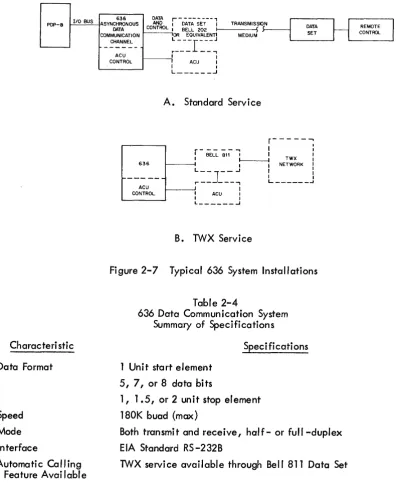
ASYNCHRONOUS DATA COMMUNICATION CHANNEL TYPE 636
The Type 636 Asynchronous Data Communication Channel is available on special order for
use with the PDP-8 in applications where program-supervised control of an associated data set is a
re-quirement. The 636 offers approximately the same data handling features as the PT08 equipment but
includes automatic answering logic and includes an Automatic Calling Unit Control feature. The
sys-tem can also
be
ordered for operation through a Bell Model 811 Data Set forTWX
service. A typical installation is shown in Figure 2-7. Specifications are summarized in Table 2-4.PDP-8 I/O BUS
Characteri stic
Data Format
Speed
Mode
Interface
Automatic Calling Feature Available
636
ASYNCHRONOUS DATA
OATA
CO~~L : REMOTE
CONTROL COMMUNICATION
CHANNEL
---r -O-;';A-;E~ -
-1
TRANSMISSION_I
OATAH
OR B~'tUI~~~NT:1---M-E-OIU-'iJ
S---I
SETL-_-r-_-J
L - -_ _ ~ ' -_ _ _ --'r--- --,
ACU I I
CONTROL
:
ACU II
L ______ .J
A. Standard Service
636
r---, I
r - BEU. ~,;- ~
I
:
I I---l TWX I
1---1 I I NETWORK I
r
-L __ ] __ ..J I :
r - - - ,
L ______
JACU
CONTROL t---! I ACU I I
I I
L _ _ _ _ _ _ ...J
B. TWX Service
Figure 2-7 Typical 636 System Installations
Table 2-4
636 Data Communication System Summary of Specifications
1 Unit start element
5, 7, or 8 data bits
Speci fi cati ons
1, 1.5, or 2 unit stop element
180K buad (max)
Both transmit and receive, ha/f- or full -duplex
EIA Standard RS-232B
TWX service available through Bell 811 Data Set
DP02A/DP03 AUTOMATIC DIALING EQUIPMENT
This equipment enables a PDP computer to control up to four Bell 801 (or equivalent)
Automatic Calling Units (ACU). Normally the automatic calling units are associated with data sets
connected to a PT08 or DP01A serial data channel, as shown in Figure 2-8.
The DP02A Auto Dial Multiplexer provides the basic computer interface and mounting
faci-1ities for up to four DP03 Automatic Dial Out Units. Each DP03 provides a control interface to one
[image:30.615.97.494.55.555.2]Under program control, thi s equipment sends a call request to the ACU. When a I ine is
available, the ACU requests the digits of the number to be called, one at a time. In response to each
digit request, the computer delivers the digits in BCD form. After dialing is completed, the ACU waits
for an answer from the called station; when an answer signal is detected, the ACU transfers control to
the associated data set. The computer can then send and receive messages on the active line through
the data set. When a message exchange is complete, the program can request the ACU to terminate
the call (hang up).
PT08 r---- DATA (8 OR C)
: PT08F ONLY I
FAMILY
OF 1/0 BUS
8 CONTROL I
COMPUTER I I DP03 -!
'---"'SYNCHRoNOUS
l.---.
~=~or~=~
ACU ~ L.. _ _ _ _ _ .J
(UP TO DP02A 4 DP03 UNITS)
r----,j:0NTROL I
: DP03
DATA AND DP01A CONTROL j
"!
Figure 2-8 DP02A/DP03 ACU Control Equipment Configurations
PARALLEL DATA CHANNELS
All the preceding communication systems are intended for transmission of serial digital data,
usually over long distances. Another category is parallel transfers between two nearby computers or
between a computer and on an electromechanical device or display system. Two computers can, of
course, be linked by serial character channels. However, data exchanges then take place at limited
speed and require direct program control. More efficient for transfer of large blocks of data between
computers is a parallel communications channel that, preferably, operates memory -to -memory without
program intervention. DEC suppl ies para II el interprocessor interfaces for all the PD P computers and
be-tween PDP computers and those of a number of other manufacturers, as standard equipment. Parallel
interfaces to other devices are usually avai lable as a special system design.
Interprocessor Buffers
The parallel interface arrangement between computers is usually done when the computers
are in the same "room and a high data rate or device simulation is desired.
Usually the PDP interfaces to a large data processing computer as a peripheral device, and
communication is controlled by the large computer on a memory-to-memory transfer basis.
Interfaces to most manufacturer1s computers are available in the DEC communication product
line. Some of these are
I
isted below.Available as a standard option:
IBM 360
a. Selector channel
b. Multiplexer channel
Available through special systems:
CONTROL DATA
a. 3600
b. 3200
c. 6600
d. 160A
e. 160G
SDS
a. 930
b. 940
UNIVAC
a. 1107
b. 1108
IBM
a. 7090
b. 7094
c. 7040
d. 7044
BURROUGHS
a. 5500
Parallel Devices
Parallel interfaces from PDP computers to electromechanical devices and display systems are
COMMUNICATION SYSTEM EXAMPLES
The following systems are representative applications of DEC communications equipment in
transportation, computer time rental, data processing, and process control.
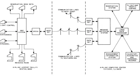
Airl ine Reservation and Management System
Figure 2-9 shows a part of a communication network that might be used by a large airline
with a central traffic control, reservation, and management information center centrally located in
Chicago, and with communication facilities at all the major airports in the U. S. The hypothetical
"Boston, Mass." communication facility is shown at the left. It consists of a 680 system as a message
concentrator connected to low -speed airl ines terminal faci lities throughout the airport: reservation
desks, flight control, maintenance, personnel, and a message room. Entries from, and responses to,
these terminals are routed through the 680 system to a DP01A synchronous modem interface, which
operates through a common carrier such as the dial telephone network.
At the Chicago end of the line, data and messages from a" airport terminals are processed
and suitable replies or inquiries generated. A single large data processor thus has direct access to
up-to-date information from all regional sites, and in turn, any of the regions can request processed
reservation data, flight or traffic control information, management guides, accounting, or personnel
records.
Systems of this sort can be expanded to any size or number of channels within the data
proc-essing capabi lity of the main computer insta"ation.
RESERVATION DESK SETS
FLIGHT CONTROL
MAINTENANCE
6BO SYSTEM
MESSAGE ROOM
AIRLINE AIRPORT FACILITY BOSTON, MASS
COMMUNICATION LINES TO WEST COAST
COMMUNICATION LINES TO SOUTHERN USA
AIRLINE COMPUTER CENTER CHICAGO, ILLINOIS
Figure 2-9 Communication Equipment in Commercial Data Processing and Control Network
[image:33.613.81.539.408.658.2]Time-shared Computer Service
Figure 2-10 shows a communication faci Iity for time -sharing of a large computer installation
through conventional telephone lines. Three installations are involved; a large data processing
instal-lation in Los Angeles, California; a computer time rental service in Boston, Mass.; and a
rental-service customer in one of the Boston suburbs.
Each rental-service customer uses a keyboard/printer unit with a built-in data set for manual
dialing over standard telephone lines. The time rental office has a 680 system equipped to receive data
inputs. The 689/ADF options provide for automatic answering and automatic call ing, if necessary.
Data from all customer lines is assembled by the PDP-8 computer {in the 680 system} and transmitted on
a single high -speed serial synchronous channel through a DP01A, which in turn drives a modem
con-nected to the long -distance communication line.
,---,
I COM:~TSETRO~I~~F~~ENTAL I
OTHER TIME RENTAL USERS
680
SYSTEM
SERVICE I
I I
I .. I
I
I I I It OPTIONAL
- - - _______ -.1
~M-:L~N:N~R:G ~R~
I I
I TELETYPE I
I I
I
I
I
I
I L . . . -_ _ - l I
I DIALING I
L _
B~S~N~~R~ .-.lr---- ....
I LOCAL I I TELEPHONE :
I CO. I
L _ _ _ _ ...J
OTHER USERS ( SOUTHWEST)
OTHER USERS ( NORTHWEST)
DATA PROCESSING CENTER COMPUTER TIME RENTAL
SERVICE
[image:34.613.73.557.277.595.2]LOS ANGE LES, CALIF.
Multi - Terminal Data Processor
Figure 2-11 shows a large -scale data processor, such as the PDP-1 O~ connected to a variety
of remote peripheral and communication equipment through a PDP-8 operating as a communications
contro"er. The PDP-8 is shown contro" ing four medium or high -speed serial channels, three handl ing
synchronous data and one for asynchronous data. A type 680 system operating as a message
concen-trator, and a type 338 graphic display system, are shown as two of the synchronous data terminals.
(Both the 680 and the 338 employ a built-in PDP-8 and thus can interface directly to a DP01A
ronous interface.) Special equipment such as a character display might al so be connected to a
synch-ronous channel. (The display controller and synchsynch-ronous data interface are special system designs.)
The asynchronous channel might be used to interface to line printers or card readers in a remote batch
processing terminal; again, the device control equipment and serial asynchronous interface are special system designs.
SERIAL DATA LINES
MESSAGE LINE CONCENTRATOR
680
SYSTEM
DEC
338
DISPLAY SYSTEM
CONTROLLER
DISPLAY CONTROLLER
r---,
r--,
DATA DATA
r - - - - I SET SET
L_~ L_~
*
SPECIAL SYSTEMLARGE DATA PROCESSOR
INTER-PDP -8 PROCESSOR
BUFFER
Figure 2-11 Communication Equipment in large - Scale Data Processor
[image:35.617.76.528.277.594.2]Centrally tv\onitored Process Control Sites
The multiprocessor system illustrated in Figure 2-12 provides maximum flexibility and growth
potential in a process control appl ication wi thout compromi sing essential on - I ine control functions.
Small satellite control computers handle the basic on -line control operations, while a central data
processing system supervises and optimizes the overall operation and provides for off-line activity.
The local (satellite) instrumentation control centers could consist of PDP-8 or PDP-8/S
computers equipped to interface with standard process instrumentation.
The satellite computers or data loggers communicate with the central computer via PT08
serial data channels. (lT09 equipment is similar to PT08, for the PDP-9 computer.) Many satellite
stations can be handled by a central PDP-9. Satellites could even be mounted on mobile carts, with
phone jacks instal led at each local site at which control is required.
Each satellite operates independently, scanning its inputs and delivering direct control
out-puts. Significant data is assembled and transmitted over the communication link for monitoring by the
central computer.
The central processor is thus free to supervise the entire operation, coordinate individual
satellites, and develop operating guides and optimization. New or modified programs can be developed
off -line, as in a stand -alone installation.
SPECIAL COMMUNICA TION SYSTEM REQUIREMENTS
In some situations standard DEC equipment may not be completely compatible wi
th
specialcommunication system requi rements, as where a special modem or unusual type of transmission is expected.
In many cases standard DEC items can be adapted to special appl ications by minor hardware
modifica-tions. You are invited to contact DEC sales offices for quotations on special communication system
POP-9
CENTRAL COMPUTER
IoATA - - - -
-1- - - -
-rco;mo;:- - - -
- - - r;DEPEm;E~-AQUISITION OUTPUT
SITE SITE
INPUT IOUTPUT CONTROL SITE
LIGHT
PEN
[image:37.800.174.660.54.479.2]CHAPTER 3
DEC SERIAL DATA COMMUNICATION EQUIPMENT PERFORMANCE AND INTERFACE CHARACTERISTICS
This section contains a brief functional description, performance characteristics, a summary
of software supplied and programming techniques, and detailed interface specifications for the DEC
serial communication equipment.
PT08 ASYNCHRONOUS SERIAL LINE INTERFACE
The PT08 is a serial-to -parallel, parallel-to -serial converter which provides full -duplex
communication between an asynchronous teletype -code serial device and a PDP-8 computer.
Two basic configurations are offered: PT08B, {one duplex channel} and PT08C (two duplex channels).
Systems may be expanded up to five duplex channels by stacking of PT08 units. PT08B and C are
de-signed for connection to Model 33 or 35 Teletype units (or equivalent) through Teletype Conversion
Kits (a W070 connector module and interconnecting cable assembly). Any channel can be modified
by the PT08F option for compatibility with EIA Standard R5-232A interface logic levels.
Principles of Operation
A simpl ified system diagram, Figure 3-1, shows interconnections between a PT08B, a PT08C,
and associated external equipment. One channel of the PT08C is shown with a PT08F EIA interface
option (any channel can accommodate a PT08F).
Each PT08 channel consists of control logic for communication with the computer's I/O bus
plus two special solid state FLI P CHI P modules that perform the serialparallel and parallel
-to-serial conversion. On input, the
W706
shifts in serial characters from the device; when a character isassembled, a "receive flag" is set in the control logic. The flag causes a program interrupt, and can
be tested for the "character ready" condition by an I/O skip instruction. Programmed lOT commands
transfer the assembled parallel character to the computer's accumulator.
On output, parallel characters are loaded into the
W707,
wh ich then shifts the character tothe device, adding start and stop bits. When a character is fully shifted out, a "transmit flagll in the
control logic is set. The flag can cause a program interrupt or be tested for the "ready for another
character II condition by an I/O skip instruction.
Character Format - Jumper wiring options on the
W7CJ7
andW706
modules permit a variety of characterformats in and out of each channel. Character codes of 5 to 8 bits and a stop element of
1, 1.2,
or2
units may
be
selected. A 1 -unit start element is standard.Speed - The standard data transmission speAd is 110 baud, but the hardware is capable of operation at
any speed up to lOOK baud. The PT08X option permits the user to specify the speed and input/output
PDP-B
I/O
BUS
TO ANOTHER PTOS C ASSEMBLY (UP TO 5 CHANNELS)
CONTROL
PTOB B
CONTROL
CONTROL
PT08 C
B03 W 070
BI9 W070
TELETYPE
TELEPHONE LINE
BELL 103A OR 103F DATA SET
CANNON DB25-P
TELETYPE
Figure 3-1 Typical PT08 System Cabling Diagram
lOT Instructions - The following instructions test for character-ready conditions and transfer assembled
characters to and from the computer's accumulator. The same basic commands are used for all channels.
Individual channel s are addressed by a microcoded portion of the instruction word. The octal code for
the basic PDP-8 or 8/1 Teletype KSF command is 6031; for PT08 channell the KSF command is 6401,
and so on.
Skip on Receive Flag (KSF)
Clear Receive Flag and AC (KCC)
Read Receive Buffer (Static) (KRS)
Causes the program to skip the next instruction if the receive flag is set I indicating that an assembled character is ready.
Clears the accumulator and the receive flag.
Transfers an assembled character from the receive buffer to
bits 4 through 11 of the AC. Does not reset AC or receive
flag.
[image:39.617.120.514.47.434.2]Read Receive Buffer (Dynamic) (KRB) Performs the functions of KCC and KRS together, so that the
receive flag and AC are cleared before data is transferred
from the receive buffer to the AC.
Skip on Transmit Flag (TSF)
Clear Transmit Flag (TCF)
Load Transmit Character (TPC)
Load Transmit Sequence (TLS)
Causes the program to skip the next instruction if the
trans-mit flag is set, indicating that the transtrans-mit buffer is ready
for another character.
Resets the transm i t fl ag •
Loads the transmit buffer from bits
4
through11
of the AC,and initiates shifting of the character out to the device or
communi cation channel.
Performs the functions of TCF and TPC together.
Maintaining Maximum Data Rates - Both in transmitting and receiving, the PTOS allows a full character
cycle for the program to del iver or read in new data. However, for maximum data transfer rates, the
time at which data transfer can occur is limited to an aperture equal to the stop bit time plus half a bit
time. This response time is measured from the beginning of a stop bit (the time at which the transmit
or receive flag is reset) and the midpoint of the next character's start bit. If the program fails to
respond within this time, a character is lost. Timing is illustrated in Figure 3-2.
STOP BIT TIME
BIT TIME ---1 ~ (BIT TIME X STOP UNITS)
(1/BAUD RATE) ---j ~ :
START DATA BITS : : STOP :START DATA BITS
CHARACTER I
i-IT - - - -
i -! I l T
-TIMING LJ __ :_ J..- _ _ _ _ ~ _ ~
y_
1- _ _ _ _I I
I I
I ,
I I
I I
TRANSMIT O R .
L
LAST TIME TORECEIVE FLAG RESET --.l RESPOND TO FLAG
Figure
3-2
PTOS Program Response TimeFor example, at
110
baud(9.09
ms bit time), response time is:Stop bit time + half a data bit time