Order No. AA-K176A-TK
DEenet
DIGITAL Network Architecture
Network Services Protocol
Functional Specification
(NSP)
DEenet
DIGITAL Network Architecture
(Phase III)
Network Services Protocol
Functional Specification
(NSP)
Order No. AA-K176A-TK
Version 3.2.0
October 1980
This document describes the Network Services architecture, which models that part of the DECnet software that supports the creation and destruction of logical links, error control, and flow control. Network Services is part of the DIGITAL Network Architecture.
First Printing,
October 1980
This material may be copied, in whole or in part, provided that the copyright notice below is included in each copy along with an
acknowledgment that the copy describes protocols, algorithms, and
structures developed by Digita~ Equipment Corporation.
This material may be changed without notice by Digital Equipment Corporation, and Digital Equipment Corporation is not responsible for any errors which may appear herein.
Copyright
~
1980 by Digital Equipment CorporationThe postage-prepaid READER'S COMMENTS form on the last page of this document requests the user's critical evaluation to assist us in pre-paring future documentation.
The following are trademarks of Digital Equipment Corporation:
DIGITAL DEC PDP DECUS UNIBUS
COMPUTER LABS COMTEX
DDT DECCOMM ASSIST-ll VAX
DECnet DATATRIEVE
DECsystem-10 DECtape DIBOL EDUSYSTEM FLIP CHIP FOCAL INDAC LAB-8
DECSYSTEM-20 RTS-8
VMS lAS TRAX
MASSBUS OMNIBUS OS/8 PHA RSTS RSX
1.0 2.0 2.1 2.2 2.3 2.4 2.4.1 2.4.2 2.4.3 2.4.4 2.5 2.6 2.6.1 2.6.2 2.6.3 2.6.3.1 2.6.3.2 2.6.4 2.7 2.7.1 2.7.2 3.0 3.1 3.2 3.3 4.0 4.1 4.2 5.0 S.l 5.2 5.3 5.4 5.5 6.0 6.1 6.2 6.3 6.4 6.4.1 6.4.2 6.4.3 6.5 6.6 6.6.1 6.6.2 6.6.3 6.7 6.8 6.9 CONTENTS INTRODUCTION
FUNCTIONAL DESCRIPTION Design Scope
Relation to DIGITAL Network Architecture Transport Characteristics
Basic Network Services Concepts Logical Links and Ports
Port and Logical Link States Logical Link Identification Data Flow
Messages
Major Network Services Functions
Establishing and Destroying Logical Links Error Control
Flow Control
Normal Data Flow Control Interrupt Data Flow Control
Segmentation and Reassembly of User Data Messages Functional Components
Data Bases and Buffer Pools Modules
NSP INTERFACES
Session Control Interface Network Management Interface Transport Interface
NSP STATES Port States
Logical Link States
NSP DATA BASES AND BUFFER POOLS NSP's Internal Data Base
Session Control Port Data Base Reserved Port Data Base
Node Data Base Buffer Pools·
DETAILED FUNCTIONAL MODEL Interface Routines
Receive Dispatcher Module Index to Routines
Receive Processes
Connect/Disconnect Receive Processes Data Receive Processes
Reserved Receive Processes Reassembly Module
Transmit Processes
Connect/Disconnect Transmit Processes Data Transmit Processes
Reserved Transmit Processes Transmit Format Module Segmentation Module
Transmit Allocation Module
7.0 7.1 7.2 7.3 7.4 7.5 8.0 8.1 8.2 8.3 8.3.1 8.3.2 8.3.3 8.4 8.4.1 8.4.2 8.4.3 8.5 8.5.1 8.5.2 8.5.3 8.5.4 8.5.5
CONTENTS (Cont.)
ALGORITHMS
Data Segment Retransmission Other-Data Handling
Retransmission Timer Value Estimation Inactivity Timing
Confidence Testing MESSAGE FORMATS
Message Format Notation General Message Format Data Messages
Data Segment Message Interrupt Message Link Service Message Acknowledgment Types
Data Acknowledgment Message
Other-Data Acknowledgment Message Connect Acknowledgment Message Control Messages
No Operation Message Connect Initiate Message Connect Confirm Message Disconnect Initiate Message Disconnect Confirm Message
APPENDIX A LOGICAL LINK ADDRESS ASSIGNMENT/DEASSIGNMENT
ALGORITHM EXAMPLE A.l
A.2 A.3
APPENDIX B B.l
B.2
APPENDIX C C.l
Interface to the Algorithm Data Structures
Algorithm Operation
SEGMENTATION MODULE EXAMPLE Data Structures
Operation
REASSEMBLY MODULE EXAMPLE Data Structures
C.2
APPENDIX D 0.1
Operation
TRANSMIT ALLOCATION MODULE EXAMPLE Data Structures
D.2 0.3
APPENDIX E E.l
E.2
GLOSSARY
FIGURE 1 2 3 4 5 6 7
Primitive Functions Operation
DIFFERENCES BETWEEN NSP V3.2 AND NSP V3.l Interface Differences
Protocol Differences
FIGURES
Relation of Network Services to DNA
Model of Data Flow as Seen by Session Control Connection with Acceptance
[image:5.615.66.550.78.752.2]CONTENTS (Con t. )
Page
FIGURES (Cont.)
FIGURE 8 Segment Acknowledgment Operation 12
9 Example of Segment Flow Control for Normal Data on a
Logical Link 14
10 Interrelationship of NSP Components 16
11 Port State Diagram 37
12 Logical Link State Diagram 39
TABLES
TABLE 1 NSP Messages
2 Port States
3 NSP's Internal Data Base
4 Session Control Port
5 Reserved Port
6 Node Descriptor
7 Index to Routines Used in Model
8 34 40 41
1.0 INTRODUCTION
This document describes the structure, functions, interfaces, and
protocols of Network Services. Network Services, also known as NSP
(Network Services Protocol), is that part of the DIGITAL Network
Architecture (DNA) that models the software (or hardware) enabling the
creation and destruction of logical communication links, data flow
control, end-to-end error control, and the segmentation and reassembly of messages.
DIGITAL Network Architecture is the model on which DECnet
implementations are based. A DECnet network is a family of software
modules, data bases, and hardware components used to tie DIGITAL
systems together for resource sharing, distributed computation or
remote system communication.
DNA is a layered structure. Modules in each layer perform distinct
functions. Modules within a single DNA layer (but typically in
different computer systems) communicate using specific protocols.
Modules in different layers (but typically in the same computer
system) interface using subroutine calls or a system-dependent method.
In this document interfaces are described in terms of calls to
subroutines.
This specification describes Phase III NSP architecture. In Phase II,
an earlier version, Session Control was part of NSP. with Phase III,
Session Control has been logically separated from NSP, and the
interface between the two layers defined. The Session Control layer
is described in a separate functional specification. The routing
specification, also a part of the Phase II NSP specification, has been greatly expanded in Phase III and is contained in a separate Transport
specification. Appendix E details the differences between Pnase II
and Phase III NSP.
A glossary at the end of this document defines many Network Services
terms.
This document assumes that the reader is familiar with computer
communications and DECnet. The primary audience consists of those who
implement DECnet systems, however, the document may be useful to
anyone interested in the details of DECnet structure. The other DNA
Phase III functional specifications are:
DNA Data Access Protocol (DAP) Functional Specification, Version
5.6.0, Order No. AA-K177A-TK
DNA Digital Data Communications Message Protocol (DDCMP)
Functional Specification, version 4.1.0, Order No.
AA-K175A-TK
DNA Maintenance Operations Protocol (MOP) Functional
Specification, Version
2.1.0,
Order No. AA-K178A-TKDNA Transport Functional Specification, Version 1.3.0, Order No.
AA-K180A-TK
DNA Network Management Functional Specification, Version 2.0.0,
Order No. AA-K18lA-TK
DNA Session Control Functional Specification, Version 1.0.0,
Order No. AA-K182A-TK
The DNA General Description (Order No. AA-K179A-TK) provides an
2.0 FUNCTIONAL DESCRIPTION
Network Services Protocol (NSP) performs the following functions:
1. Enables the creation and destruction of virtual channels
(logical links) that can be used for sending messages within
a network node and between network nodes.
2. Manages the movement
transmit buffers to
mechanisms.
of interrupt and
receive buffers,
normal data from
using flow control
3. Breaks up normal data messages into portions (segments)
can be transmitted individually, and reassembles
segments in their correct order after they have
transmitted.
that these been
4. Guarantees the delivery of data and control messages to a
specified destination by means of an error control mechanism.
Section 2 is an overview of NSP, covering the following topics:
• Design scope (Section 2.1)
• Relation of NSP to the DIGITAL Network Architecture (Section
2.2)
• Transport characteristics (Section 2.3)
• Basic concepts (Section 2.4)
• Messages (Section 2.5)
• Major functions (Section 2.6)
• Functional components (Section 2.7)
2.1 Design Scope
Network Services satisfies these following design requirements:
1. Compatibility. Network Services version 3.2 is compatible
with NSP version 3.1, except for those differences described
in Appendix E.
2. Performance. Network Services allows an implementation to
perform without deadlocks while using dynamic buffer pools.
3. Promptness. Network Services minimizes the delays incurred
in moving data from one Session Control module to another.
4. Efficiency. Network Services
overhead (for example, line
protocol.
minimizes the communications
5.
Extensibility.
functions
in
subset.
Network
Services accommodates
additional
the
future,
leaving
earlier
functions as a
6.
Fairness.
If more than one logical link
is established
to
the
same
destination at
the
same
time, Network Services
assures that each provides useful communication services.
7.
Elasticity.
Network Services allows
an
implementation
to
trade memory resources (both algorithm complexity and buffer
pool sizes) for performance.
The following are not within the scope of Phase III Network Services:
1.
Maximum throughput.
Network Services will
not
necessarily
maximize the throughput of a logical link.
2.
Uniform service.
Network Services will
not guarantee
the
same
average
throughput and average delays over two logical
links from a common source to a common destination.
2.2
Relation to DIGITAL Network Architecture
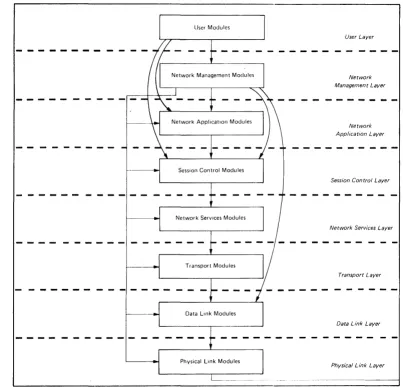
Figure 1 shows
the
relatlonship
hierarchy.
Each
layer
in DNA
protocols.
of Network
Services
to
the DNA
consists of functional modules and
Generally, modules use the services of the next lowest layer.
In this
document
the
service
relationship
is demonstrated
in the way the
interfaces are modeled -- as calls to
subroutines.
Note,
however,
that the Network Management layer interfaces directly with each of the
lower layers.
Also, all the layers above
Session Control
interface
directly with
it.
In
fact,
the
upper three layers are sometimes
referred to as the "end user."
Modules of the same type in the same layer communicate with each other
to provide their services.
The rules governing this communication and
the messages required
constitute
the
protocol
for
those modules.
Messages
are
typically exchanged
between
equivalent modules
in
different nodes.
However, equivalent modules within a single node can
User Layer
Network Management Layer
Network Application Layer
Session Control Layer
Network Services Layer
Transport Layer
Data Link Layer
Physical Link Layer
Horizontal arrows show direct access for control and examination of parameters, counters, etc. Vertical and curved arrows show interfaces between layers for normal user operations such as file access, down-line load, up·line dump, endto·end looping, and logical link usage.
Figure 1 Relation of Network Services to DNA
A brief description of each layer follows in order from the highest to
the lowest layer:
1. User layer. The highest layer, the User layer supports user services and programs. Programs such as the Network Control Program, which interfaces with the Network Management layer, and file transfer programs, which interface with the Network Application layer, reside in the user layer.
[image:10.613.96.499.75.462.2]3. Network Application layer. Modules in the Network
Application layer support network functions, such as remote
file access and file transfer, used by the User and Network
Management layers.
4. Session Control layer. The Session Control defines the
system-dependent aspects of logical link communication, which
allows messages to be sent from ohe node to another in a
network. Session Control functions include name to address
translation, process addressing, and, in some systems,
process activation and access control.
5. Network Services layer. The Network Services layer defines
the system-independent aspects of logical link communication.
6. Transport
messages, nodes.
layer. called
Modules packets,
in the
between
Transport layer route
source and destination
7. Data Link layer. The Data Link layer defines the protocol
concerning data integrity and physical channel management.
8. Physical Link layer. The Physical Link layer encompasses a
part of the device driver for each communications device plus
the communications hardware itself. The hardware includes
interface devices, modems, and the communication lines.
2.3 Transport Characteristics
NSP interfaces directly with the Transport layer for its services.
Transport is a datagram delivery service to NSP. A datagram is a
block of data sent intact from one DECnet node to another. Transport
sends datagrams in packets. NSP expects Transport to have the
following characteristics:
1. Transport will accept a datagram at least as large as 230
8-bit bytes.
2. There is an extremely low probability that Transport will:
a. Duplicate a datagram
b. Deliver a datagram to the wrong destination
c. Change the data in a datagram
3. Transport may fail to deliver a datagram.
4. Transport may fail
destination from a
transmitted.
to deliver datagrams
given source in the
to a given
order they were
5. Datagrams delivered to a given destination from a given
source undergo a variable delay while under the control of
Transport. However, this maximum delay is bounded.
Datagrams not delivered within the maximum delay will not be
2.4 Basic Network Services Concepts
This section describes concepts that are fundamental to an
understanding of NSP.
1. Logical links and ports (Section 2.4.1)
2. Port and logical link states (Section 2.4.2)
3. Logical link identification (Section 2.4.3)
4. Data flow (Section 2.4.4)
2.4.1 Logical Links and Ports - NSP provides a logical link service
to Session Control. A logical link is a virtual connection between
two Session Control modules, either between two nodes or within one
node. The connection enables controlled communication between network
nodes. A pair of Session Control modules may have more than one
logical link between them. Each logical link is separate from all
other logical links.
Each logical link must have a port at each end. A port is an area in
memory, generally in a dedicated or shared pool, that contains control
variables for managing logical links. Table 4 in Section 5.2
specifies these variables. NSP manages ports. Each node on a network
has a number of available ports. In forming a logical link, one port
is associated with another.
When Session Control requests a logical link or requests that a port
be opened to receive an incoming connect request, NSP allocates a port
if sufficient resources are available. When Session Control requests
that a port be closed, NSP deallocates the resources associated with
the port. Deallocation usually occurs after Session Control requests
a logical link disconnection.
NSP also maintains a "confidence" variable in each port that has been
opened. Session Control has access to this information, which is
useful in detecting network failures.
2.4.2 Port and Logical Link States - Each end of a logical link is in
one of a set of states at any time. In other words, each port has a
state.
The states at one end of the link affect the states at the other end
of the link. In this document the possible link states at one end of
a link are called the port states. The logical link states are the
combination of possible states at both ends of the logical link.
Every logical link has its own set of logical link states.
Session Control requests and NSP messages determine the particular
states and state transitions of the logical link. NSP manages these
state changes, based on the particular requests and messages it
receives. Section 5 details all the normal port and logical link
2.4.3 Logical Link Identification - In order for two NSP modules to
manage a given logical link, each NSP module must be able to identify
the link. The logical link identification consists of the port
addresses at each end of the link.
Each NSP module assigns a l6-bit numerical address to its end 'of a
logical link. The port at one end of the link contains the address of
the port at the other end of the link and vice versa. This is the way
in which the two ports are associated with each other. The complete
identification of the link, identifying both ends of the link, is
therefore a 32-bit number.
To avoid using the same number to identify two different links, an NSP module refrains from assigning a 16-bit address it used for a previous
(but now disconnected) link to a new link as long as possible. The
probability that each of the two NSP modules reassigns its 16-bit
address and that these two addresses are paired a second time during a
connection process is extremely low. Therefore, the probability that
the same 32-bit identification would exist for two different links is
very low. This ensures that there will be no cross-talk between
links.
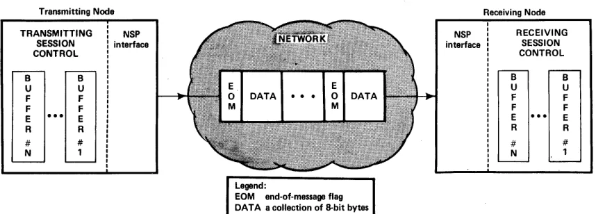
2.4.4 Data Flow - After a logical link is established, data may flow
in both directions (full-duplex) from transmitting Session Control
transmit buffers through the network to receiving Session Control
receive buffers. The size of the buffers at each end of the link is
implementation-dependent. However, the data flowing through the
network is always handled the same way. The NSP interface to Session
Control takes Session Control data provided in DATA-XMT calls (Section
3.1). It then transforms the data to a network form. At the other
end of the link the receiving NSP interface, responding to Session
Control DATA-RCV calls, transforms the data from its network form to
its receive buffer form. The mechanisms NSP uses to handle data are
transparent to Session Control. From Session Control's viewpoint, the
data flow is as shown in Figure 2.
Transmitting Node TRANSMITTING SESSION CONTROL B U F F E R # N B U F F E R # 1 NSP interface Legend:
EOM end-of-message flag OAT A a collection of 8-bit bytes
NSP interface
Receiving Node RECEIVING SESSION CONTROL B U F F E R # N B U F F E R # 1
This figure shows Session Control data transformed from a transmitting Session Control to a transmitting NSP and then transformed back from a receiving NSP to a receiving Session Control. The NSP data does not actually move through the network as shown. (The DNA General Description
shows how Transport packets actually move through the network.)
[image:13.612.98.527.458.612.2]The transmitting NSP appends the end-of-message (EOM) flags (Figure
2), to the data in the network form. The receiving NSP module removes
these flags, places only data in the Session Control receive buffers,
and then informs the receiving Session Control via a flag in a
returned receive buffer whether an EOM was received. Section 3.1
details this procedure.
Throughout the data flow places data bytes from a in the same order as they
that no data will be
procedure.
2.5 Messages
process, NSP preserves data order. NSP
single transmit buffer into the network form
were in the buffers. NSP also guarantees
lost. Section 3.1 details the data flow
In order to provide logical link service, flow control and error
control (thereby supporting the Session Control interface), NSP
modules in different nodes must communicate. They do so by sending
and receiving NSP messages. The NSP protocol consists of these
messages and the rules governing their exchange.
There are three types of NSP messages:
• Data messages
• Acknowledgment messages
• Control messages
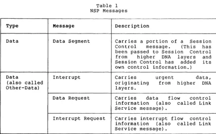
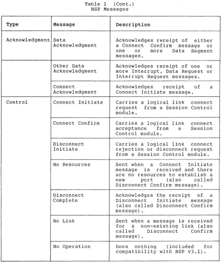
Table 1 summarizes the functions performed by each NSP message.
Section 8 describes the message formats in detail.
Type
Data
Data
(also called Other-Data)
Message
Data Segment
Interrupt
Data Request
Table 1 NSP Messages
-.
Description
Carries a portion
Control message.
of a Session
(This has
been passed to Session Control
from higher DNA layers and
Session Control has added its
own control information.)
Carries urgent data,
originating from higher DNA
layers.
Carries data flow control
information (also called Link
Service message) .
Interrupt Request Carries interrupt flow control
information (also called Link
Service message) .
[image:14.617.93.520.412.676.2]Table 1 (Cont.) NSP Messages
Type Message
Acknowledgment Data
Acknowledgment
Control
Other Data Acknowledgment
Connect
Acknowledgment
Connect Initiate
Connect Confirm
Disconnect Initiate
No Resources
Disconnect Complete
No Link
No Operation
2.6 Major Network Services Functions
Description
Acknowledges receipt of either
a Connect Confirm message or
one or more Data Segment
messages.
Acknowledges receipt of one or
more Interrupt, Data Request or Interrupt Request messages.
Acknowledges receipt of
Connect Initiate message.
a
Carries a logical link connect
request from a Session Control
module.
Carries a logical link connect
acceptance from a Session
Control module.
Carries a logical link connect
rejection or disconnect request from a Session Control module.
Sent when a Connect Initiate
message is received and there
are no resources to establish a
new port (also called
Disconnect Confirm message) .
Acknowledges the receipt of a
Disconnect Initiate message
(also called Disconnect Confirm message) .
Sent when a message is received
for a non-existing link (also
called Disconnect Confirm
message) .
Does nothing (included for
compatibility with NSP V3.l).
This section summarizes the operation of the major NSP functions which include:
1. Establishing and destroying logical links (Section 2.6.1)
2. Error control (Section 2.6.2)
3. Flow control (Section 2.6.3)
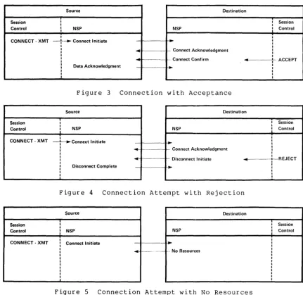
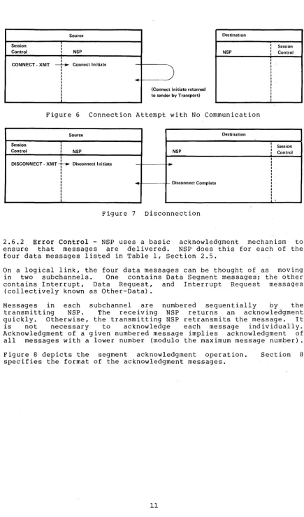
[image:15.613.96.530.58.572.2]2.6.1 Establishing and Destroying Logical Links - A source NSP and a
destination NSP exchange messages to establish and destroy (in other
words, to connect and disconnect) logical links. Figures 3 through 7
summarize the message exchanges. The calls in capital letters under
Session Control headings are names of interface functions as described
in Section 3.1. The message exchanges below will take place correctly
in an implementation, if the algorithms in Section 4 are followed.
Source Destination
Session i i Session
I I
Control I NSP NSP
:
ControlI
I I
CONNECT-XMT ---}---.. Connect Initiate I I
I I
I Connect Acknowledgment I
I I
I I
I Connect Confirm
..
I ACCEPTI I
I Data Acknowledgment I
I I
I I
I I
I I
Figure 3 Connection with Acceptance
Source Destination
Session I I Session
I I
Control
:
NSP NSP:
ControlI I
CONNECT-XMT ~Connect Initiate
..
II
I - Connect Acknowledgment I
I
.-
II I
I I
I
-
Disconnect Initiate . . - - - t - -REJECTI I
I Disconnect Complete
...
II
I I
I I
I I
Figure 4 Connection Attempt with Rejection
Source Destination
Session ! ! Session
Control
,
NSP NSPI Control
CONNECT - XMT Connect Initiate
...
- - - ---- -- No Resourcesj
[image:16.618.94.526.135.554.2]Session I
Control I I I I
CONNECT-XMT ~
I I I I I I I I I
:
Source
NSP
Connect Initiate
(Connect I nitiate returned
y Transport) to sender b
Destination
NSP
Figure 6 Connection Attempt with No Communication
Source Destination
Session i
I
Control I NSP NSP
I I
DISCONNECT - XMT ~ Disconnect Initiate
I I I I
I Disconnect Complete
I I I I
1
Figure 7 Disconnection
Session Control
Session Control
2.6.2, Error Control - NSP uses a basic acknowledgment mechanism to
ensure that messages are delivered. NSP does this for each of the
four data messages listed in Table 1, section 2.5.
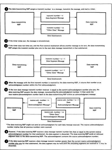
On a logical link, the four data messages can be thought of as moving
in two subchannels. One contains Data Segment messages; the other
contains Interrupt, Data Request, and Interrupt Request messages
(collectively known as Other-Data) .
Messages in each subchannel are numbered sequentially by the
transmitting NSP. The receiving NSP returns an acknowledgment
quickly. Otherwise, the transmitting NSP retransmits the message. It
1S not necessary to acknowledge each message individually.
Acknowledgment of a given numbered message implies acknowledgment of
all messages with a lower number (modulo the maximum message number) .
Figure 8 depicts the segment acknowledgment operation.
specifies the format of the acknowledgment messages.
[image:17.615.88.524.15.755.2] [image:17.615.91.522.46.409.2]o
The data-transmitting NSP assigns a transmit number to a message, transmits the message, and starts a timer.Data-transmitting NSP
1---transmit number = n Data Segment Message
transmit number = m "Other Data" Message
Data Subchannels
o
If the timer times out, the message is retransmitted.---
....
---+
Data-receiving NSP
o
If the timer does not time out, and the flow control mechanism allows another message to be sent, the data-transmittill9 NSP assigns the transmit number plus one to the next data message transmitted in that subchannel.Data-transmitting NSP
~---- transmit number = n + 1
Data Segment Message
transmit number = m + 1 "Other Data" Message
Data Subchannels
---
....
---+
Data-receiving NSP
o
When the message with the first transmit number is received by the data-receiving NSP, it returns that number as an acknowledgment number within the first acknowledgment.o
If the next data message transmit number received is equal to th'!~IJ.!.':_nt ac~~owle~gme~t numbe~~~~, the data-receiving NSP accepts the data message, incrementing the acknowledgment number. It then sends the new receive acknowledgment number back to the data-transmitting NSP within an acknowledgment message.Data-transmitting NSP
j - - - -- - I
: receive ack. number = n :
f+--:
Data :...--: Acknowledgment Message* :...--:L ___________________ I
receive ack. number = n + 1 Data Acknowledgment Message
receive ack. number = m
for---
"Other Data" ---Acknowledgment MessageData Subchannels
Data-receiving NSP
·The data-receiving NSP might not send an acknowledgment for each data message received. The receive acknowledgment number implies that all previous numbers were received.
o
However, if the data-receiving NSP receives a data message transmit number less than or equal to ~he current receive acknowledgment number for that subchannel, the data segment is discarded. The datil-receiving NSP sends an acknowl-edgment back to the datil-transmitting NSP. The acknowlacknowl-edgment contains the receive acknowlacknowl-edgment number.o
If the data-receiving NSP receives a data message transmit number greater than. the current receive acknowledgmentnumber plus one for that subchannel, the data segment may be held until the preceding segments are received or it may be discarded.
[image:18.613.124.503.48.556.2]2.6.3 Flow Control - Flow control is the mechanism that determines
when to send an NSP Data Segment or Interrupt message. This
mechanism, along with the error control mechanism, coordinates the
flow of data on a logical link from transmit buffers in one node to
receive buffers in another node.
Flow control is performed separately for normal and interrupt data.
Flow control operates symmetrically ~or data flow in each direction, on
a logical link.
2.6.3.1 Normal Data Flow Control - Flow
algorithms for normal data:
control requires two
1. An implementation-dependent algorithm executed
data-receiving NSP that determines both when to
request message and the count value to be put into a message.
2. An algorithm executed by a data-transmitting NSP
determines if a Data Segment message may be sent.
by a
send a request
that
In addition, an "on/off" control mechanism may be used by a
data-receiving NSP to indicate to a data-transmitting NSP that Data
Segment messages mayor may not be sent.
On/off control. On/off control is independent of the request count
control. It operates as follows: Each Data Request message contains
a "send/do not send" indicator. When the error control mechanism in a
data-transmitting NSP has received and accepted a Data Request
message, the value of the "send/do not send" indicator is saved in the
data base associated with the logical link. When the value is "do not
send," the data-transmitting NSP may not transmit normal data. When
the value is "send," the data-transmitting NSP exercises the flow
control mechanisms described next.
Request count flow control. During logical link formation, the NSP at
each end of the link determines the kind of flow control it expects
when acting as a data receiver. The term "data-receiving NSP" means
an NSP acting as a data receiver. There is a choice of:
• No flow control
• Segment flow control
• Session Control message flow control
The choice of flow control is indicated via fields in Connect Initiate
and Connect Confirm messages. Each data-transmitting NSP must accept
the type of flow control the data-receiving NSP expects.
A data-transmitting NSP maintains a "transmit request count" variable
for normal data in the data base associated with each logical link.
When the error control mechanism receives and accepts a Data Request
message, flow control adds the count value from the message to the
appropriate transmit request count. The count values contained in the
request messages may be zero, positive, or, in some cases, negative.
This additive scheme works because the request messages are
error-controlled; it would not work otherwise.
NSP/Node A "Data-Transmitting"
NSP/Node B "Data- Receivi ng"
o
NSP/Node A sends a Connect Initiate message to NSP/Node B:o
o
o
o
8
e
Lc_o_n_n_e_ct ___________ Initiate
J~---~~~
NSP/Node B, having received the Connect I nitiate message, returns a Connect Confirm message. A field in the message indicates that NSP/Node B expects segment flow control:
"I want segment flow controlU ,
..
NSP/Node A's data base has the initial value of rp for its request count variable for normal data segment flow control:
NSP/Node B sends a Data Request message containing a flow control value that indicates the number of Data Segment messages NSP/Node B can receive. (NSP/Node B executes an implementation-dependent algorithm to determine this value):
"I can receive n messages"
..
Data)]
Request
NSP/Node A sets F LOWrem_dat to n:
NSP/Node A executes algorithm to determine if Data Segment number 1 can be sent (highest acknowledged Data Segment message plus the current request count must be greater than or equal to the number of the next Data Segment message sent):
7NO -
~"·t
..
ndYES
I
send
The answer to the above is YES, so NSP/Node A sends Data Segment number 1:
Data Segment 1
NSP/Node B acknowledges receipt of first data segment:
..
o
NSP/Node A subtracts 1 from its flow control request count:Data Acknowledgment of segment number 1
Figure 9 Example of Segment Flow Control for Normal Data on a
[image:20.620.91.539.46.582.2]Segment flow control. Figure 9 shows an example of the operation of
segment flow control. Segment flow control operates in the following
manner: If the data-receiving NSP selected the segment flow control
mechanism when the logical link was formed, the highest numbered Data
Segment message that may be transmitted is the one whose number is
equal to the sum of the highest numbered Data Segment message that has
been acknowledged (via the error control mechanism) by the
data-receiving NSP plus the current value of the request count. The
data-transmitting NSP decrements its request count variable by one for each Data Segment message acknowledged by the data-receiving NSP.
The count values that can be contained in Data Request messages may be
negative. This means that the permission to transmit a particular
Data Segment message (even if it has been previously transmitted) may
be withdrawn by the receiver. This, in turn, causes an interaction
between the flow control and error control mechanisms. Specifically,
it is not necessary for the error control mechanism to maintain an
active retransmission timer for a Data Segment message that has been
transmitted at least once but for which permission to transmit (in
other words, to retransmit) has been withdrawn.
Session Control message flow control. If the data-receiving NSP
selected Session Control message flow control, the data-transmitting
NSP cannot send a segment if the number of end-of-message segments
between the highest acknowledged segment and the segment in question
(exclusive) is greater than or equal to the count. The
data-transmitting NSP decrements its request count variable by one for
each Data Segment message that is an end-of-message segment
acknowledged by the data-receiving NSP.
The mechanism for Session Control message
interact closely with the error control
mechanism for segment flow control). Once a
given permission to be transmitted, the
withdrawn.
flow control does not
mechanism (unlike the
Data Segment has been
permission will never be
2.6.3.2 Interrupt Data Flow Control - All NSPs use interrupt data
flow control for moving interrupt data. This mechanism is similar in
operation to the Session Control message flow control mechanism.
Interrupt message request counts are carried in Interrupt Request
messages. The counts are additive and may not be negative. The
interrupt-transmitting NSP can, therefore, maintain an interrupt
transmit request count. When a logical link is established, there is
an implicit request of one interrupt message. The interrupt
transmitting NSP cannot send an Interrupt message if the number of
Interrupt messages between the highest acknowledged Other Data message
and the Interrupt message in question is greater than or equal to the
count. The interrupt-transmitting NSP decrements its request count
variable by one for each Interrupt message acknowledged by the
interrupt-receiving NSP.
2.6.4 Segmentation and Reassembly of User Data Messages - Because of
network constraints such as available buffer sizes and transmission
error characteristics, user messages in Session Control buffers cannot
always be sent in one piece. A data-transmitting NSP breaks up data
contained in a single Session Control buffer into segments. A
data-receiving NSP reassembles the segments. The data-transmitting
NSP transmits the segments by means of Data Segment messages. The
data-receiving NSP puts the segments from the Data Segment messages
The data-transmitting NSP must know
the
maximum
length of
a
Data
Segment.
This length is the lesser of:
1.
The size of a transmit buffer in the source node.
This
size
cannot be larger than the node's Transport layer will permit.
2.
The maximum length that the data-receiving NSP
can
receive.
The SEGSIZE field in the Connect Initiate and Connect Confirm
messages,
exchanged
when
the
logical
link was
formed,
contains this information.
The data-receiving
number
contained
information.
When
they
are
either
(Section 2.7.1).
NSP orders the data
segments
using
the
sequence
in
the
Data
Segment message
and end-of-message
Data Segments have been received out of
sequence,
discarded
or
stored temporarily in a cache buffer
This document does not specify the detailed processes of
segmentation
and
reassembly.
However,
Sections
6.5 and 6.8 provide a model for
implementation and Appendixes Band C provide examples.
2.7
Functional Components
In its relation to DNA, NSP can be considered
a
"black
box,"
which
interfaces
to Session Control and Transport by defined interfaces and
with
other
NSP
modules
by
the
Network
Services
Protocol.
The
functional components in this section and in Sections 5 and 6 describe
the operation of this "black box" by means of a sample implementation.
Any
other
implementation with
equivalent operation
is also
a
legitimate NSP implementation.
NSP
consists of data
bases,
buffer
pools,
and
modules.
Brief
descriptions of each
follow in this section.
Section 5 details the
data base and buffer pool
specifications.
Section
6
specifies
in
detail
the
operation of the NSP modules with a model implementation
written in a high-level,
colloquial
computer
language.
Figure
10
shows the interrelationship of the NSP components.
2.7.1 Data Bases and Buffer Pools - The following is a model
of
the
NSP data bases:
NSP internal data base.
The NSP internal data
base
contains
NSP's
internal variables and
parameters.
Variables are values defined by
NSP.
Variables change automatically during
the
operation of
NSP.
Parameters
are values defined
by the Network Management interface.
Parameters can be read and sometimes set by the user.
Many parameters
are
static in
the sense that they remain set until the user changes
them.
session Control port data base.
The Session Control
port data
base
contains
the
port 'variables that NSP uses to manage a logical link.
When a logical link is created, NSP allocates a Session
Control
port
to
it. When the link is destroyed, NSP releases the port back to the
port data base as a free port.
Reserved port data base.
The reserved port data
base
contains
the
port variables
reserved
for
NSP's internal use.
NSP uses these to
manage the sending of messages
that do
not map
onto
the
Session
SEG-MENTATION MODULE
TRANSMIT PROCESSES
I
TRANSMIT ALLOCATION MODULE
TRANSMIT FORMAT MODULE
I
SESSION CONTROL
INTERFACE ROUTINES
1 " - - _ - "
[image:23.613.95.514.53.374.2]PORT DATA BASES
... -"
LARGE AND SMALL ... - - - + 1 TRANSMIT
BUFFER POOLS ... ~
1
t
TRANSPORT
...
-
-"CACHE AND COMMIT REASSEMBLY _ BUFFER
MODULE POOLS
RECEIVE PROCESSES
... -~
RECEIVE RECEIVE
L - -_ _ ~ DISPATCHER f+--- BUFFER
MODULE POOL
... -~
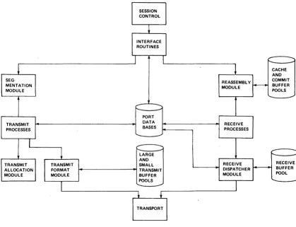
Figure 10 Interrelationship of NSP Components
Node data base. The node data base contains a collection of node
descriptors. A node descriptor is required for each remote node to
which a logical link is established. A node descriptor contains
variables and counters pertaining to communications with that node
(for example, the estimated round trip communications delay, traffic
usage and error counters)-.
Large and small transmit buffer pools. The large and small transmit
buffer pools contain large and small transmit buffers. Large transmit
buffers transmit Connect Initiate messages or Data Segment messages.
Small transmit buffers transmit all other NSP messages. An
implementation may choose to use a single transmit buffer pool for all NSP messages.
Receive buffer pool. The receive buffer pool contains a collection of
receive buffers required to receive an NSP message from Transport.
Commit buffer pool. The commit buffer pool is an optional pool which
contains commit buffers used for data that the receiving node may
commit to storage even in the absence of receive buffers supplied by
Session Control. Such data may be acknowledged to its transmitter.
Cache buffer pool. The cache buffer pool is an optional pool which
contains a collection-of cache buffers. Cache buffers hold received
are out of order or because there is no storage in either a commit buffer or a Session Control receive buffer for them.
Event buffer pool. The event buffer pool contains buffers that may be
queued to NSP's event queue for reading by Network Management.
2.7.2 Modules - NSP modules perform specialized functions. There are
two kinds of modules:
1. A process is a module that is independent of other modules,
but uses the services of some other modules. It is designed
as if it were executing on a processor dedicated to it.
2. A routine is a module that provides functions for one or more
processes, but does not have a context of its own.
In general, processes communicate with routines by means of calls and
with other processes by means of shared variables, usually a port.
The mechanisms that synchronize two processes to prevent common entry
to a critical region are not explicitly defined.
The NSP process and routine modules are described below. Note that
these are functional descriptions of components. Implementations need
not be structured exactly as outlined in these descriptions.
Interface routines. The interface routines handle all Session Control
calls (Section 3.1).
Receive dispatcher routine. The receive dispatcher manages the
receive buffer pool. It polls Transport for received messages, parses
them, maps them onto ports, and returns message contents to the
appropriate NSP process.
Receive processes. These receive and handle NSP messages from Network
Services at remote nodes and help manage logical link states. Each
Session Control port has a set of these processes.
Reassembly routine. The
control policy, maintains
reassembles received Data
receive buffers.
reassembly routine determines the flow
the cache and commit buffer pools, and
Segment messages into Session Control
Transmit processes. These transmit (and retransmit, if necessary) NSP
messages to Network Services at remote nodes. Each Session Control
port has a set of these processes.
Transmit format routine. The transmit format routine maintains large
and small transmit buffer pools and formats outgoing messages. It
queues messages to Transport. It polls Transport to get "transmit
completell
notifications.
Segmentation routine.
buffers into a form
messages.
This segments data in Session Control
suitable for transmission in Data
transmit Segment
Transmit allocation routine. The transmit allocation routine receives
requests for permission to transmit from the transmit processes. It
allocates permission to transmit in a way that guarantees that when
more than one logical link is established to the same destination at
3.0 NSP INTERFACES
This section describes the three external Network Services (NSP)
interfaces:
1. Session Control interface
2. Network Management interface
3. Transport interface
The interface functions are described as calls to subroutines in the
following format:
FUNCTION (input; output)
Descriptions of input and output then follow unless previously given.
In general, there are two types of subroutines: those performing a
function that is completed immediately, and those queueing a buffer
for transmitting or receiving data.
For buffer-queueing calls, additional calls are defined to allow
poll ing to obta in "buffer returned" not if icat ions. A "buffer"
argument denotes a system-dependent buffer descriptor that contains
location and length information. A "port id" is a system-dependent
number identifying a port. Although not described in the following
functions, an invalid port identifier causes an error.
Note that an implementation is not required to code the interfaces as
calls to subroutines. The calls specify functions only.
It may be useful to refer to the port state descriptions in Section
4.1 when studying the following interface functions.
3.1 Session Control Interface
This interface allows NSP to provide Session Control with the logical
link service. This service allows Session Control to create one or
more logical links to one or more other Session Control modules in the same network.
In the interface descriptions, the terms "source" and "destination"
distinguish the requestor of a function from the receiver of the
request. The source and destination can be within a single Session
Control module or in two separate Session Control modules. Thus, at a
single node, a Session Control module can communicate with itself via
a logical link; between two nodes, two Session Control modules can
communicate with each other via a logical link.
The calls, described by function, are as follows:'
STATUS (; NSP status)
returns: NSP is halted.
NSP is running; minimum receive buffer
(NSPbuf -- Table 3, Section 5.1) returned
size
This function reads the status of NSP and obtains a minimum
OPEN (source, buffer; return)
source: a 16-bit buffer to contain the logical link requestor
node address when this node receives a connect
request
returns: port allocated and port identifier returned
port not allocated insufficient resources
port not allocated NSP halted
This function allocates a port in NSP for receiving a logical
link connect request. The source variable receives the node
address of the requesting node; the buffer receives the
incoming connect data. When the port state indicates an
incoming connect request is received, NSP places the source
node address in the source variable and the incoming data in
the buffer.
CLOSE (port id)
This function deal locates a port. When a port is closed, NSP
immediately returns all transmit and receive buffers to Session
Control (see DATA-XMT and DATA-RCV calls). Once a port is
closed, its associated port identifier is undefined. Any
subsequent call issued with such a port identifier results in
an error return.
Session Control may close a port at any time regardless of the
port's state. However, doing so may create ambiguities for the
Session Control module at the other end of the logical link.
CONFIDENCE (port id; confidence)
returns: network probably connected
network probably disconnected
port not in RUNNING, CONNECT-CONFIRM,
DISCONNECT-REJECT, or DISCONNECT-INITIATE state
This function obtains NSP's assessment of connectivity. NSP
periodically tests a logical link once it is formed to
ascertain if the physical path supporting the link is
connected. The result of this testing is the probable state of
connectivity. It is not a guaranteed state.
Session Control may issue this call to determine when to
STATE (port id; state)
returns: the state of the associated logical link
This function returns the state of a port that is not CLOSED.
Because NSP's operation is not necessarily synchronized with
that of Session Control, it is possible that this call will not
detect every state transition. This is especially the case for
state transitions that occur very quickly. However, this is
not a problem because the intervening undetected states can be
logically deduced.
CONNECT-XMT (destination, channel, buffer; return)
destination: destination node address
channel: an internal NSP mechanism selector used to enable
loop testing. Channel is either unspecified (for
normal use) or a system-dependent line number
representing the line NSP is to use for its messages
establishing this logical link (for Network
Management loop tests) .
returns: port allocated; port id returned
port not allocated insufficient resources
port not allocated NSP halted
This function allocates a port and requests a logical link
connection. After a logical link has been successfully formed,
Session Control can put a load on a particular physical link
for loop test purposes provided that the channel argument
specified the physical link. This enables testing of the
physical link and all of the DECnet modules from Session
Control or higher layers by sending and receiving data on the
resulting logical link. For normal use, the channel argument
is set to "unspecified."
CONNECT-STATUS (port id, buffer; return)
returns: connect request accepted by destination port in
RUNNING state; accept data returned in buffer
connect request rejected by destination port in
REJECTED state; reject data returned in buffer
port in neither RUNNING nor REJECTED state
This function obtains accept or reject data returned as a
result of a previous connect request. If the return is one of
the first two, NSP returns any available accept or reject data.
Once this is done, an NSP implementation may discard its copy
of the accept or reject data so that a subsequent connect
status function would not return data.
In cases where state transitions occur very rapidly, Session
Control may not be able to perceive some intervening states.
Accept data will be lost if the rapid state transitions end with a transition to the DISCONNECT-NOTIFICATION state and this
call was never executed in the RUNNING state. No data is lost
otherwise.
If the connect request is accepted, up to 16 bytes of accept
data may be returned in the buffer. If the connect request was
rejected, up to 18 bytes of reject data may be returned in the
buffer (see the ACCEPT and REJECT calls).
ACCEPT (port id, buffer; return)
returns: link accepted
port not in CONNECT-RECEIVED state
This function accepts a connect request from a remote Session
Control module. The call supplies a buffer containing up to 16
bytes of accept data.
REJECT (port id, buffer; return)
returns: link rejected
port not in CONNECT-RECEIVED state
This function rejects a connect request from a Session Control
module. The call supplies a buffer containing up to 18 bytes
of reject data.
DISCONNECT-XMT (port id, buffer; return)
returns: call accepted
call rejected -- port not in RUNNING state
This function requests the disconnection of a logical link that
is in the RUNNING state. The call supplies a buffer containing
up to 18 bytes of disconnect data.
The remote Session Control module receives any data transmitted by the disconnecting Session Control module prior to this call.
Session Control disconnects a link when it has no more data to
send and wants to ensure that the link will be properly
disconnected, not aborted.
ABORT-XMT (port id, buffer; return)
returns: call accepted
call rejected -- port not in RUNNING state
This function requests the immediate disconnection of a logical
link that is in the RUNNING state. The remote Session Control
module may not receive all previously transmitted data before
receiving the abort notification.
DISCONNECT-RCV (port id, buffer; return)
returns: disconnect data available
no disconnect data available
port not in DISCONNECT-NOTIFICATION state
This function receives disconnect data returned to the local
Session Control module as a result of a DISCONNECT-XMT or
ABORT-XMT call from the remote Session Control module. Session
Control detects a logical link disconnection or an abort when a
STATE call returns a DISCONNECT-NOTIFICATION. Up to 18 bytes
of data may be returned in the buffer.
DATA-XMT (port id, buffer, xmtflag; return)
xmtflag: a flag indicating whether the last byte in the buffer
is the last byte of a Session Control message. Its
value is one of:
• end-of-message
• not-end-of-message
Section 2.4.4 describes data flow.
returns: buffer queued
buffer not queued -- insufficient resources
port not in RUNNING state
This function queues a transmit buffer to a port for
transmitting normal data on a logical link. NSP refuses to
queue the buffer either if it lacks,the resources to do so or
if the port is not in the RUNNING state.
XMT-POLL (port id; return)
returns: no tranmsit complete
transmit complete -- buffer descriptor returned
This function returns a transmit buffer to Session Control.
DATA-RCV (port id, buffer, rcvflag; return)
rcvflag: a flag indicating whether data truncation is allowed.
It may have either of the following values:
• no truncation allowed
returns: buffer queued
buffer not queued insufficient resources
buffer not queued buffer too small and no
truncation was specified in rcvflag
port not in RUNNING or DISCONNECT-INITIATE state
This function queues a receive buffer to a port to receive
normal data. A "buffer too small" return indicates the buffer
size is smaller than the minimum receive buffer, NSPbuf (see
STATUS) .
Session Control may provide a buffer to a port in the
DISCONNECT-INITIATE state to avoid a Session Control deadlock
in which each end of the logical link is in the
DISCONNECT-INITIATE state. However, this is an
implementation-dependent issue.
RCV-POLL (port id; return)
returns: no buffer returned (Either
queued to the port or
available.)
no receive buffers are
there is no receive data
buffer returned no data lost, end-of-message
buffer returned data lost, end-of-message
buffer returned no data lost, not end-of-message
buffer returned data lost, not end-of-message
buffer returned empty port not in RUNNING,
DISCONNECT-INITIATE, DISCONNECT-COMPLETE, or
DISCONNECT-NOTIFICATION states.
This function obtains a "receive complete" notification for a
receive buffer previously queued via a DATA-RCV call. NSP
returns receive buffers along with buffer descriptors to
Session Control in the order in which data was placed in them.
A data-transmitting NSP segments data given to it by the
DATA-XMT call and sends each segment separately through the
network. A segment containing data given to NSP with an
"end-of-message" flag is so marked. A data-receiving NSP
receives these segments and places the data in Session Control
receive buffers given to NSP by the DATA-RCV function. The
sequence of packets flowing from a data-transmitting NSP to a
data-receiving NSP constitutes the network form described in
Section 2.4.4.
If a data-receiving Session Control module gives NSP each
receive buffer with the rcvflag set to "no truncation allowed"
on the DATA-RCV call, then NSP attempts to place the data, in
order, from one or more segments of a single Session Control
message into each receive buffer. A receive buffer is always
returned with a "no data lost" indication and is returned with
an "end-of-message" indication if and only if the last segment
of data placed in it was marked as ah "end-of-message" segment.
Control module, one with data that is not marked
"end-of-message" and the second with no data but marked
"end-of-message," may result in data and status being given to
the data-receiving Session Control either in two buffers, as
given to NSP by the data-transmitting Session Control module,
or in a single buffer containing the data and marked as
"end-of-message."
If a data-receiving Session Control module gives NSP each
receive buffer with the rcvflag set to "truncation allowed,"
then NSP either fills the receive buffer or puts data into it
up to and including the data in a segment marked as
"end-of-message" whichever comes first. If a receive buffer is
filled first, then NSP continues to receive and discard data
segments up to and including the first one marked as
"end-of-message." In either case, the receive buffer is
returned as an "end-of-message" on the RCV-POLL call. In the
case where data was discarded, the receive buffer is returned
with a "data lost" indication. The only time a buffer given
with a "truncation allowed" rcvflag is returned as
"not-end-of-message" is when the logical link is disconnected
by the data-transmitting Session Control module with a
partially transmitted message.
A data-receiving Session control module may mix calls with the
"truncation allowed" rcvflag with calls with the "no truncation allowed" rcvflag.
If Session Control closes
queued via the DATA-RCV
immediately.
a port
call,
INTERRUPT-XMT (port id, buffer; return)
returns: data accepted
data not accepted
port not in RUNNING state that NSP
has receive
returns these
buffers buffers
This function sends up to 16 bytes of high priority data to the
destination Session Control module. The data has no sequential
relationship to normal data transferred on a logical link. NSP
may refuse a request to send interrupt data if it is unable to
queue the data internally. The buffer may be up to 16 bytes
long.
INTERRUPT-RCV (port id, buffer; return)
returns: data returned
no data returned
port not in running state
This function obtains available interrupt data. Interrupt data
is delivered in the order transmitted by the INTERRUPT-XMT
function. Interrupt data has no sequential relationship to