HYBRID PROGRAMMING: A COMPREHENSIVE "SOFTWARE" PACKAGE FOR HYDAC
®
INTRODUCTION
The discovery quite early in the "computer age" that a series of programming aids were needed to circumvent or reduce the tedious, time-consuming and expensive operations required in using digital computers - coding, program testing, interpret-ing results, etc - led to the development of auto-matic programming language systems, "canned" routines, and other prepared procedures variously referred to as 'software."
Software, in effect, permits the user to 'get at' the computer without 'getting in it'. Through the use of such programming aids, for example, it is possi-ble to introduce to the computer a complete set of instructions regarding mathematical routines, nu-merical operations, logic and control schemes and data transfer or storage programs without needing to know the disposition of each octal subroutine, register, flip-flop, or storage cell. Indeed, the creation of this programmed interface between the user and the machine has made the task of digital computer programming easy for the non-computer-expert, and is responsible for the almost universal acceptance of the digital computer in the scientific field.
The Problem of Communication: Despite the several benefits accrued through the use of such software packages - increased computer utilization, re-duced duplication of effort for general utility pro-grams, minimized periods of operator training, etc - the introduction of this interface has erected a barrier which not only restricts the analystfrom communicating with his computer model during computation but often limits the programmer him-self from taking full advantage of the digital com-puter's special features.
In the analog computer field the reverse situation exists. No comparable "software" interface has developed and the computer user communicates directly with the machine. There is little need to preserve standard programs; the analyst/pro-grammer is directly involved in building the
com-puter model and maintains rapport with the model throughout the problem.
The Uniqueness of Hybrid Simulation: The role that software must play in hybrid simulation is predi-cated on the unique combination of digital accuracy and analog speed that is hybrid simulation . .. the combination that permits the use of the best fea-tures of each in a particular problem solution. As a result, "hybrid software" must ease the pro-grammer's burden as does digital software so that full utilization can be made ofthe digital computer's memory, logic and resolution.
At the same time, hybrid software must bring the analyst closer to the model rather than isolating him from it. The interface "barrier" of digital software, which renders the digital machine essen-tially into a sealed "black box," must be lowered to allow the effective interaction of the analog and digital domains. Accordingly, hybrid software must include coding for the sequential computer to per-form internal calculations and make decisions as well as control facets of parallel machine opera-tions and also inter-connection diagrams and pre-wired patch panels for the parallel machines. GENERAL REQUIREMENTS
The hybridization of digital and analog techniques into hybrid simulation has not, despite their union in use, altered the specifiC features of either method of computation. As a result, the capabilities of conventional digital software systems, although useful in hybrid computation, must be extended to provide programming aids for the entire system.
Compilers and Assemblers: Conventional compilers and assemblers which, in digital systems, provide automatic conversion from a symbolic to a ma-chine language program, have a useful function in hybrid simulation as well, but differ in their utili-zation in four ways:
(1) Program running time is minimized at the expense of compiling time.
(2) Actual running time for each program statement is pre-calculated or estimated to aid the programmer with the timing aspects of the problem.
(3) Since the programmer must be able to use special machine features in order to program for control of all machine inter-face operations, a machine-dependent pro-grammer's language is utilized in most cases.
(4) The programer's language is extended to all sections of the hybrid system to aid in programming not only the digital, but also the machine interface and analog sections as a system entity.
Debugging Aids and Diagnostics: Conventional soft-ware aids for debugging a digital program include memory dwnp, updater, and tracer routines; diag-nostics usually check out the proper operation of the digital processor hardware. Hybrid software must extend these capabilities for the entire sys-tem and provide additional features as follows:
(1) Analog Section Diagnostics - a symbolic program which accepts a problem-oriented language description of the analog flow dia-gram and automatically produces (a) setup documents (pot sheets) for the analog run, (b) digital static check calculations for the analog program, and (c) possibly an analog program dynamic check calculation.
(2) Logic and Data Transfer Diagnostics - a digital program which is used to ascertain that the linkage, interface, and logic hard-ware are operating properly and checks out (a) the bidirectional data flow, (b) the bidirectional control signal flow, and (c) the logic and secondarystorage compon-ents, etc.
Appendix A, Figure 1 shows an excerpt from a representative diagnostic check.
Subroutine Library: The conventional subroutines prepared for a general purpose hybrid computer include:
(1) Mathematical routines (log, In, exponen-tial, sine, cosine, tangent, arctangent, square root).
(2) Computational routines (single precision floating point, double preciSion floating point, double preCision fixed point).
2
(3) Conversion routines [(double and single precision) BCD/fixed point, BCD/floating point, fixed pOint/floating pOint)].
(4) Input/Output (I/O) routines (typewriter, paper tape, magnetic tape, automatic for-matting on output).
(5) Algorithms (a selection of numerical algo-rithms: integration methods, etc.).
(6) Models (subsystems, environments, etc.).
With regard to Item (5), Algorithms, there is fre-quent need in a hybrid system for various numeri-cal operations such as definite integrals, the solu-tion of differential equasolu-tions, etc.; in addisolu-tion, sub-routines mechanizing various integration methods (Runge-Kutta, Adams, Milne, Euler, etc.) have been constructed. These utility routines permit the pro-grammer to choose the method exhibiting the best speed and accuracy for his particular problem.
With regard to Item (6), Models, there is frequent need in a hybrid system for useful subsystem mod-els that have become standard and are used in larger models (specific transfer function routines for use in a typical servo controller, for example, or a function generator program for any number of aerodynamiC functions). A standard program for a complete aerodynamic vehicle simulation is of value in many aerospace computing laboratories. These utility routines ease the programmer's task by permitting use of standard models and elimi-nating duplication of effort.
HYDAC 2400 SOFTWARE REQUIREMENTS: THE EAI SOFTWARE PROGRAM
The EAI Software Program outlined in the block diagram of Figure 1, is the comprehensive hybrid software 'package' offered by EAI to provide the users of the HYDAC 2400 Computing System with the necessary programming tools.
The three essential elements of a hybrid computing system are the parallel computer(s), the sequential computer, and the software or programming sys-tems that transform the former two into an operable simulation tool. Of great importance to the effective use of a hybrid computing system is the software "man-machine interface."
The parallel engineer-oriented aspects of the gen-eral purpose analog computer -- pioneered by EAI
with the PACE ® 231-R Computing System -- have
EAI SOFTWARE PROGRAM
I. PER IPHERAL EQUIPMENT CONTROL
2. I/O FORMAT CONTROL
3. OPERATION OF MONITOR SYSTEMS
I
1
STANDARD MONITOR SYSTEM SI MULATION MONITOR SYSTEM HYTRAN* MONITOR SYSTEM
I. ASSEMBLER I. HYBRID MODE CONTROL I. STATIC CHECK
2. FORTRAN n 2. INTEGRATION CONTROL 2. REPORT GENERATOR
3. SUB-ROUTINE LIBRARY
4. LOADER AND RELOCATER
3. FUNCTION GENERATOR LOADER
41 HYBRID COMPUTER SET-UP
3. EQUIPMENT CHECK-OUT
4. ANALOG PROGRAM GENERATOR
5. DE- BUGGING 5. DE-BUGGING
Figure 1: Block Diagram of EAI Operating System
With the introduction of the HYDAC 2400 hybrid computing system, however, having, as a basic com-ponent, a general purpose digital computer, EAIhas developed the necessary hybrid software capabili-ties in such a way that full advantage is taken of the unique capabilities of both analog and digital tech-niques.
In addition, by recognizing the communicationdiffi-culties posed by the conventional digital software approach, EAI has formulated this software pack-age to reflect the parallel engineer-oriented as-pects of the analog computer. To facilitate this, it becomes necessary only to remember the three phases of problem implementation on the computer. Phase one involves program preparation and isdi-rectly related to phase two, program checkout. The third phase consists of simulation operation. It is
to these three aspects (program preparation, pro-gram checkout, simulation operation) of problem solving in hybrid computation that the EAI Software Program is directed. The purpose of this program is to put the user in control of his model, the com-puters, and the results of the simulation study. Thus the Standard Monitor System (sequential program
*
A Service Mark of EAt.preparation and checkout), the Simulation Monitor System, and the HYTRAN Monitor System (parallel program preparation and checkout) operate in such a way as to maintain the integrity of the system.
The following sections will describe the elements of the EAI Software Program.
STANDARD MONITOR SYSTEM
The Standard Monitor System is a complete paral-lel entity within the EAI Operating System which provides basic digital software for the EAI Series 375 Digital Computer (DDP-24).
1. Assembler: This is ametaprogram t which enables the user to write in symbolic ma-chine language. A resultant translation provides the user with an edited listing of his original program and a condensed version of the code on punched paper tape. Several parts of a program may be "as-sembled" at different times to be linked together later and loaded automatically.
[image:3.631.52.550.37.363.2](a) DAP (Digital Assembly Program) As-sembler: a metaprogram based on the SHARE standard assembler.
(i) DAP - Off- Line Output Program pun c h e s paper tape instead of listing program on the typewriter during assembly. Paper tape can be used for typewriter listing on standard tape preparation unts or on existing ADIOS* desk units. Procedure reduces digital com-puter time required for on-line program assembly.
(ii) AD IOS/DDP Conversion Program permits use of ADIOS desk for "off-line" tape pre par at ion, eliminates time-wasting digital computer tape preparation pro-cedures.
(iii) DAP Time Pseudo Operation Program provides estimate of actual machine time required to execute commands as they occur in user's program, provides ba-sis for allocation of tasks in any hybrid simulation.
2. FORTRAN II: Thi sis an engineering/ algebraic compiler for flexible, automatic formatting of input-output programs, which is easy to learn, use and debug. Object programs are compatible with DAP con-densed output tape format.
(a) In-Line Machine Language Coding with FORTRAN: The 375 FORTRAN Compiler includes special provision for real-time and hardware-oriented programming. A capability to write DAP-like entries "in-line" with the algebraic statements gives the pro-grammer a control over computation not afforded by any competi ti ve FORTRAN System. This ability is a necessity if any compiler metapro-gram is to be used to generate the codes for a hybrid computation.
(b) Expanded Features of 375 FORTRAN: Although compatible with the gen-erally-accepted FORTRAN II com-piler, the 375 FORTRAN compiler has been extended to include the most
*A Trade Mark of EAI.
4
des ira b I e f eat u res of the new FORTRAN IV version as defined by IBM for its large scale computers.
3. Sub·Routine Library: This is a set of sub-routines which perform useful or stand-ard calculations or manipulations which can be incorporated easily into the user's own program. This library tends to grow as more and more diversified applications are programmed. A written procedure describing the requirements, inputs, out-puts, range of computation, and limitations of each subroutine accompanies a paper tape version (either in symbolic DAP, FORTRAN, or machine code) of the sub-routine.
(a) Basic Digital Sub-Routines:
(i) Computational...
ADDX, SUBX, MPYX, DIVX:
double precision fixed point
FADD, FSUB, FMPY, FDIV:
single and double precision float-ing point
POLY: odd polynomial evalua-tion (used by many mathematical subroutines)
(ii) MathematicaL ..
(a) fixed point, single and double
precision
SQRX, SQDX: square root
EXPX, EXDX: exponential
LG2X, DPL2: logarithm, base 2
LGEX, DPLE: logarithm, base E
LGAX, DPLT: 10 gari thm, base 10
SINX, SNDX: sine X, input in radians
T ANX, TNDX: tangent X, in-put in radians
A TNX, A TDX: arctangent X, output in radians
(b) floating point, single and double precision
FSQR: square root
FEXP: exponential
FLG2: logarithm, base 2
FLGE: logarithm, base e
FLGA: logarithm, base 10
FSIN: sine, input in radians
FCOS: cosine, input in radians
FTAN: tangent, input in radians
F A TN: arctangent, output in radians
(iii) Conversion (single and double precision). . •
XBXD: binary-to-decimal, fixed point
XDXB: decimal-to-binary, fixed point
FBFD: binary-to-decimal, fixed to floating point
FDFB: decimal-to-binary, float-ing to fixed point
FBXD: binary-to-decimal, float-ing point
FDXB: decimal-to-binary, float-ing point
(iv) Input-Output .•.
PTIN, PTOU: paper tape
I/o
TYIN, TYOU: typewriter I/O
R 0 uti n e s for on-line printer, magnetic tape, light pen/ scope, and disk also are available.
(v) Algorithms .•.
( a) Integration
• Euler
• Heun
• Milne
• Runge-Kutta
• Adams
(b) Function Generation
Appendix A, Figure 2 shows an excerpt from a representative Model subroutine.
4. Loader and Relocator: The Loader per-forms the basic operations of loading absolute and reI 0 cat a b I e DAP and/or FORTRAN object (binary output) taped programs in memory, scanning the library tape automatically for standard subrou-tines, and creating linkages between the subroutines and the main program. (The program also records storage allocations and, through the Relocater, makes the memory assignment or avoids inadvertent destruction of stored information by typing an error message when a relocatable pro-gram is loaded. In addition, the Loader/ Relocater can be instructed to relocate a program already in memory. )
5. De-bugging: This is a program-testing communications package for on-line type-writer and console-controlled de-bugging.
The program can be used to call for:
a) point-to-point tracing of a program b) clear, dump, and search of memory c) display and entry of instructions and
data
program. Thus, loading, relocation and de-bugging operations all can be per-formed with references made to symbolic addresses.
SIMULATION MONITOR SYSTEM
The Simulation Monitor System, illustrated in the flow diagram of Figure 2, is another complete parallel entity within the EAI Software Program which, although it utilizes some of the routines described under the Standard Monitor System, has control of a group of programs designed specifically for more effective control and operation of either all-digital or hybrid scientific situation programs:
1. Hybriel Moele Control: This is the pro-gram that gives the digital computer the structure of a simulator in like manner to an analog console by exercising interface capabilities (including interrupts, sense lines, delays, and mode control) to achieve
real-time ~ynchronization between the
stored and the parallel computer pro-grams, and between the various computing
system elements needed in the solution of most simulation problems. The program controls a dual-processing mode bywhich
NO
it is possible to work on a second program located in a protected portion of memory when the' computing system is not em-ployed on the primary simulation program.
(The monitor permits dual processing when the simulation program is not in the "Operate" mode.)
Appendix A, Figure 3 shows an excerpt from a rep-resentative linkage program.
2. Integration Control: The Digital Integrator Control Program is one that is requested from the monitor by the operator to change the integration algorithm. Selec-tion of algorithms is made from the Sub-routine library; initialization and time scale changes can be made also.
3. Function Generator Loaeler: The D i gi t al Function Generator Loading Program per-mits the operator to load new data or to make changes in data preViously stored in tables associated with the particular function generation subroutine. Optionally, "raw" experimental data may be loaded by using the interpolation feature to gen-erate tabular data from it.
DUAL PROCESSOR EXECUTIVE
INTEGRATION CONTROL
MODE CONTROL
K-5 ANALOG PREP.
YES
Figure 2: Flow Diagram of Simulation Monitor System
[image:6.627.105.546.416.704.2]4. Hybrid Computer Set-up: The Hybrid
Com-puter Set-up and Check Out Program, selected by typewriter through the moni-tor, provides the capability for control of analog computer mode and time scale selection, component selection, read-out, pot set and checkout as follows:
(a) Digital-Analog Control. ••
(i) K-5 Input-Output (I/O) Group
• PTIN (CR) - transfers
control to the paper tape reader
• OP (CR) • IC (CR) • HLD (CR) • ST (CR) • PS (CR)
mode control commands for the analog computer
• CS (T) X (CR) - select console # X
• LTAB (T) AAAAA-C,
AXX-YY, MX'X'-Y'Y',
# (CR) - load table of add re s se s at AAAAA [octal], column C [octaU. consisting of amplifiers AXX through (YY-l), etc.
• LTAD (T) AAAAA-C,
XX.XX, YY. YY, etc.,
# (CR) - load table with data
(P)
• SETT (T) AAAAA-C, T,
.XX (CR) - set table of pots in table starting at AAAAA, column C, type (punch) out results, if set-ting differs > .XX print error
(P)
• STCK (T) AAAAA-C, T,
.XX (CR) - check column C data vs. state of ma-chine
(P)
• SCAN (T) AAAAA-C, T
(CR) - readout
compon-ent values of column C
(P)
• DTAB (T) AAAAA, X, T,
.XX (CR) - dump
com-SCALE EQUATIONS
j
~
DRAW DIAGRAM
'../
PATCHING
MANUAL OPERATIONS
I
I
I
I
I
I
-'") v
....
)
I
vOFF-LINE
~
COMPUTE CHECK PARAMETERSJ
' Jl
COMPUTEPOT-SETTINGS
' J
ON-LINEl;t-
SETCHECK
i'r
POTSHYTRAN OPERATIONS
Figure 3: Programming an Analog Problem with HYTRAN
plete table at AAAAA on paper tape for set-up and static check "next time"
• SET (T) PX (SP) .YYYY,
(P)
T, .ZZ (CR)- set pot PXX to coefficient YYYY
and type (punch) out re-sults; indicate error if
differs >. Z Z
• CHK (T) AXX (SP) YYY (P)
.YY, T, .ZZ (CR) - check amplifier XX for YYY. YY
volts to .ZZ accuracy
(P)
• RD (T) MXX, P (CR) read multiplier XX
• SETG (T) QXX (SP) A YY, (P)
[image:7.635.317.553.46.360.2]PROBLEM
STATEMENT DIAGRAM CHECK
HYTRAN
HARDWARE
PROGRAM DOCUMENTS
D I AGNOSTICS
Figure 4: Outputs Obtained from the HYTRAN System
5. De-bugging: The Hybrid De-bug Program provides for typewriter control of:
a. K-5 Input-Output (I/O) Group
b. Interface ADDA
c. DDP De-bug
d. Read Out and Load Memory
HYTRAN MONITOR SYSTEM
The HYTRAN Monitor System is a family of meta-programs being implemented on the HYDAC 2400 Hybrid Digital-Analog Computer as a complete parallel entity of the EAI Operating System to provide digital computer assistance in the pro-gramming of its analog system. The scaling of the physical equations and the preparation of the com-puter diagram are still performed by the program-mer who thereby maintains direct control over the analog implementation of the problem. In order to permit calculation of theoretical static check values, HYTRAN also must be given the original problem statement and a set of test initial condi-tions. Additional data, including patching informa-tion, component setting or modes, highest deriva-tives, and any other expressions representing other appropriate component outputs must be provided
8
as well. In this way, the necessary rapport between the programmer and the machine is kept. Figure 3 shows the steps required to program an analog program with the HYTRAN System.
[image:8.638.86.530.45.403.2]Program input is punched on paper tape in an analog-oriented language compatible with the Series 375 Digital Computing System. The HYTRAN Sys-tem then computes potentiometer settings, and both a physical and voltage static check which are tested for consistency. Complete documentation of the analog program is produced (including potenti-ometer, amplifier, and cross-reference sheets as well as automatic pot-setting and static test tapes) in the ADIOS format. An On-Line Diagnostic Gen-erator checks measured static check voltages against the analog circuit diagram and the speci-fications of the analog components, providing a rapid means of locating patching errors or com-ponent failures.
*
HYTRAN outputs are shown in Figure 4.1. Static Check: The practice of computing two independent sets of check values has been used as the basis for the HYTRAN
Off-Line Static Check. The theoretical
static-check values in volts are computed from expressions, provided as part of the program input, which specify component outputs in terms of the scale factors, parameters, and variables of the problem. Further input defines the analog component interconnections or patching information which is used to calculate the voltage check values. In this computation, all in-put voltages to a component, the kind of input to which the component is connected, and the transfer function of the component are used to determine its voltage output.
When both voltage and theoretical values are available for a component output they are compared. If in agreement, they yield the off-line static check value for that component. If the values are not in agree-ment the error is isolated by retaining the theoretical value as the static check input for all subsequent calculations and an error message is given. Values exceed-ing the voltage range of the computer also will cause error messages but will be retained for further static check calcu-lations.
The On-Line Static Check: While in
sys-tems without digital access to the analog computer, the on-line static check must be performed by manual comparison, the availability of a digital input/output sys-tem provides the HYTRAN user with a choice of two automatic procedures for such on-line checking. One method is to feed the HYTRAN-generated static-check tape into the AD lOS de sk to obtain an automatic comparison between calculated and measured values. This method is used whenever the digital computer is not avail-able at the time of analog on-line check.
If the digital computer is available, the use of the second HYTRAN method allows an improved consistency check for de-bugging of complex problems as well as for preventive-maintenance checks. This method is implemented by feeding an
ADIOS tape containing the measured pot settings and/or outputs of all components into the digital computer. HYTRAN then checks the transfer value of each individual component and compares it with themeas-ured voltage at the component output. Thus, errors can not propagate but are pin-pointed at the component level.
2. Report Generator: This is a Documenting Program which sorts and converts the in-formation from the intermediate tape to component work sheets that contain a list of the analog computing components in an orderly sequence, together with their modes and their outputs or settings in terms of problem parameters, variables, and scale factors. In addition, an alpha-betic list of the values of parameters and variables is typed out, and ADIOS tapes are generated.
One tape contains the potentiometer set-tings in a format which allows automatic pot setting; the other tape contains the computed static-check values for on-line check with the ADIOS desk.
The Documenting Program also generates a cross-reference sheet containing an alphabetic list of symbols for parameters and variables. Each of these symbols is followed by a listing of the components whose output or settings include that symbol. This feature provides assistance in changing parameters or scale factors manually.
3. Equipment Check-out: This is an On-Line Diagnostic Program utilizing basically the same processing procedure as that of the Off-Line Static Check Generator,
4. Analog Program Generator (A proposed further development): This is a program which performs the initial step of
reduc-ing equations to a useful analog computer schematic. The three programs described above are designed to process digitally the rather tedious static check and docu-mentation routines of analog
program-ming. The Analog Program Generator
goes a step beyond these routine data-checking operations and is utilized directly in writing programs.
Although the digital computer makes use of a special internal code, or machine language, for processing information, the difficulties encountered in writing pro-grams directly in machine coding have resulted in the development of special programming languages. Information and instructions are written first in the pro-gramming language and then translated by the computer into coding which the ma-chine can understand. The compiler, or set of instrUctions, which translates this source program into a machine language (object) program also can perform other clerical functions to improve the efficiency of the procedure and relieve the program~
mer of many routine tasks. The Analog Program Generator System, therefore, makes it possible to write programs with-out a detailed knowledge of the internal organization of the computer.
A further convenience is achieved by orienting the programming language to-ward the procedure rather than the ma-chine. Programs then may be written in a language which closely resembles that of the programmer and his specific area of computer application. For example, the FORTRAN (FORmula TRANslator) pro-gramming system includes many state-ments which resemble algebraic formulae to facilitate programming numerical pro-cedures. The mathematician then may communicate more closely with the com-puter by programming in FORTRAN rather than in a business-oriented or other p:r' gramming system.
While FORTRAN programming is suitable for expressing numerical or logical re-lationships, many of the statements are too general for programming specialized operations conveniently. To improve this situation, a special programming language
10
has been defined for the HYTRAN System which allows the analog computer grammer to write digital computer pro-grams in terms and expressions familiar to him. The HYTRAN language is designed specifically to be compatible with the Series 375 Digital Computing System (3C DDP-24) which forms the arithmetic sec-tion of the HYDAC 2400 Hybrid Computer. The HYTRAN language includes state-ments which are oriented specifically to-ward analog computer programming, and which make use of the EAr 231R Analog Computer nomenclature in identifying components, modes, etc.
The HYTRAN inputs fall into two main categories: a) inputs which describe the problem to be solved, and b) inputs de-scribing its implementation on the analog computer.
a) The Problem Statement. The problem
usually is stated in mathematical no-tation. The HYTRAN program, there-fore, accepts the problem statement in a mathematically-oriented langu-age which bears resemblance to the programming languages ALGOL and FORTRAN.
The problem information to be in-putted includes parameter values, variable initial conditions, and a set of algebraic and differential equa-tions - all in terms of physical units. Parameters can be defined by ex-pressions containing numerical val-ues as well as other parameters, while initial conditions of variables can be given in terms of numerical values, parameters, or other initial conditions. All algebraic and differen-tial equations have to be in explicit form with respect to the unknown variable, or the highest derivative, respectively. Otherwise, the equa-tions should be inputted in their origi - . nal form so that any errors that may occur during further manipulations on the problem equations will show in the theoretical static check.
ten and e, and the exponent of e, In
ad-dition, the program processes cer-tain discontinuous functions - such as absolute value, sign, limits, and dead zone - which are often used in analog computation.
Relational op era to r s are another means of obtaining step-functions. They are represented by the relations
less than and greater than (for practi-cal purposes, equal to does not exist in analog computation). While a
logi-cal AND can be performed by
multi-plication, the 0 R is an explicit Boolean operator in HYTRAN.
b) Circuit Diagram Information. An
ana-log program is generated in the form of an analog circuit diagram bywhich the programmer states the outputs of components, their modes, their inter-connections (patching) , and, in the case of potentiometers and switches, their setting or position. Inputting this information enables HYTRAN to check the analog program against both the original problem input and the physical set-up on the analog computer.
The general form of a component statement is:
DESIGNATION, MODE = EXPRESSION;
CONNEC-TION
(A console number is given only when a change from one console to another occurs.)
Where
designation generally consists of an identify-ing letter and two decimal digits,
mode deSignates the configuration in which a component is used, or any special connections not involving problem variables (for example, amplifiers may be connected in integrator, summer or high gain mode),
expres sian, in the context of component state-ments, is a term or collection of terms giving, through problem variables and scale factors, the output of an analog component, and
connection is defined as a sequence of up to thirty-two input statements, each of which
11
consists of an input designation (usually identi-cal with the pre-patch panel input name) fol-lowed by the designation of the analog com-ponent which is connected to the specified input.
All computer input data is entered from punched paper tape, each type of information being pre-ceded by one of the following keywords: PARAM-ETERS, VARIABLES, EQUATIONS, COMPONENTS. The keyword sections must be presented in the order given belOW, although within any section the statements can be in arbitrary order:
i) The PARAMETERS and VARIABLES
key-words are fOllowed, respectively, by pa-rameters as used for the static check, and all variable initial conditions. Parameters and variables may be ref err e d to by mnemonic name s which, in turn, can be defined in terms of other parameters, initial conditions, or by numerical values. A name thus defined need not be referred to beforehand, but must be specified within the same keyword section.
ii) The EQUATIONS section contains the set of theoretical differential and algebraic equations to be implemented on the analog computer.
iii) The COMPONENTS keyword is followed by the patching information contained in the circuit diagram which represents the analog program. These analog patching connections, by means of which the prob-is to be implemented, are entered in any sequence.
As a simple example of how input information to the HYTRAN program is written, consider the case of a second order equation as shown in Figure 5a •. The inputs shown in Figure 5b should be provided if a complete check is desired. Note that comments pertinent to the program input, but meaningless to the digital program, can be in-serted if preceded by a tab. The input begins with the problem identification, which contains any in-formation the programmer wishes to use as a heading for all typewriter outputs. The resulting outputs are shown in Figure 6.
The HYTRAN System can increase programming efficiency and justify a high degree of confidence in the analog solution for the following reasons:
-IOOV +IOOV
w/~
Swy
~--~QOO~---<
ANALOG IMPLEMENTATION OF
d2
~+w2ycO
dt
SwyllOO
- SWy
Figure Sa: Sample Second Order Differential Equation
expressions saves programming time and prevents arithmetic errors.
2. The generation of pot-set tape saves time and eliminates the errors which could occur when transferring the numerical settings manually from a desk calculator to the I/O keyboard.
3. The documentation generated provides a complete, error-free, standard documen-tation of analog programs. Cross-referencing speeds the changing of par am-eters and scale factors.
4. The off-line static check provides acheck of every component in the computer. Auto-matic static check calculations save time and are error-free. The checking of the component level permits the omission of the check of any selected portions of the computer diagram, such as circuits that must be checked dynamically or that are considered standard routines. Such an omission prevents the checking of other components in the same algebraic chain of components.
5. Simple changes of connections,
param-eters, or scale factors may change the majority of the static-check values and pot-settings in a program, but only a
12
TEST PROBLEM #1: 2ND ORDER EQUATION
PARAMETERS
S=5 S
=
SCALE FACTORA
=
20 A=
AMPLITUDEOMEG
=
10BETA
=
10 BETA = (j = TIME SCALETO
=
1/10VARIABLES
Y'
=
A *COS (OMEG*TO)Y
=
A*SIN (OMEG*TO)/OMEGEQUATIONS
Y" = -OMEG**2*Y
COMPONENTS
POO = S*Yll00; + REF
AOO, 1= S*Y'; IC:POO
COO
=
S*Y"/(BETA*lO); l:QOOQOl
=
OMEG/BETA; AOOPOI
=
S*OMEG*Y/lOO; -REFA01, I
=
-S*OMEG*Y; IC:P01COl
=
-S*OMEG*Y'/(BETA*lO); 1:Q01A02, S
=
S*OMEG*Y; l:AOlQOO
=
OMEG/BETA; A02Figure 5b: Input Information Necessary to Program Sample
Equation
[image:12.631.58.289.48.300.2]TEST PROBLEM #1: 2ND ORDER EQUATION
STATIC CHECK VALUES
AOO
=
53.98A01 = -84.18
A02 = 84.18
COO 8.41
COl 5.40
POO = -53.98
POl 84.18
QOO 84.18
Q01 = 53.98
PARAMETERS
A 2.00000 E1
BETA 1.00000 E1
OMEG 1.00000 E1
S 5.00000 EO
TO 1.00000 E-1
VARIABLES
Y 1.68367 EO
Y'
1.07963 E1Y"
-1.68367 E2COMPONENTS
COMP MODE EXPR SETT
AOO I A*S*Y'
A01 I -A*S*Y
A02 S A*S*Y
POO A*S*Y'/100 .5398
POl A *S*OMEG*Y /100 .8418
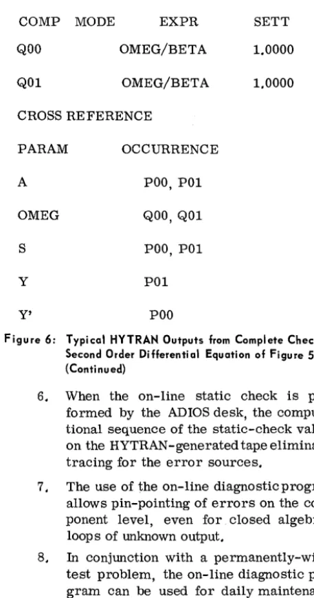
Figure 6: Typical HYTRAN Outputs from Complete Check of
Second Order Differential Equation of Figure Sa.
COMP MODE EXPR SETT
QOO OMEG/BETA 1.0000
Q01 OMEG/BETA 1.0000
CROSS REFERENCE
PARAM OCCURRENCE
A POO, POl
OMEG QOO, Q01
S POO, POl
Y POl
Y'
POOFigure 6: Typical HYTRAN Outputs from Complete Check of Second Order Differential Equation of Figure 50.
(Continued)
6. When the on-line static check is per-formed by the ADIOS desk, the computa-tional sequence of the static-check values on the HYTRAN-generated tap.e eliminates tracing for the error sources.
7. The use of the on-line diagnosticprogram
allows pin-pointing of errors on the com-ponent level, even for closed algebraic loops of unknown output.
8. In conjunction with a permanently-wired test problem, the on-line diagnostic pro-gram can be used for daily maintenance checks.
Manpower savings resulting from these features far outweigh the additional effort involved in pre-paring the HYTRAN input tape, a task comparable in size to that of preparing potentiometer and amplifier assignment sheets manually.
The system as described can be expanded easily to include new programs (such as a Digital Check Solution, for example), some of which may evolve from the practical use of the present system. Since any such new programs would require little addi-tional input information, their benefits would be available at little extra cost and would, therefore, further increase the overall economy of the system.
CONCLUSION
[image:13.631.320.549.38.473.2]APPENDIX A
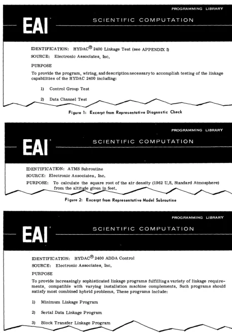
IDENTIFICATION: HYDAC® 2400 Linkage Test (see APPENDIX 1)
SOURCE: Electronic Associates, Inc.
PURPOSE
To provide the program, wiring, and description necessary to accomplish testing of the linkage capabilities of the HYDAC 2400 including:
1) Control Group Te st
Figure 1: Excerpt from Representative Diagnostic Check
IDENTIFICATION: ATMS Subroutine
SOURCE: Electronic Associates, Inc.
PURPOSE: To calculate the square root of the air density (1962 U.S. Standard Atmosphere) given feet.
Figure 2: Excerpt from Representative Model Subroutine
IDENTIFICATION: HYDAC® 2400 ADDA Control
SOURCE: Electronic Associates, Inc.
PURPOSE
To provide increasingly sophisticated linkage programs fulfilling a variety of linkage require-ments, compatible with varying instaUation machine complements. Such programs should satisfy most combined hybrid problems. These programs include:
1) Minimum Linkage Program
2) Serial Data Linkage Program
Figure 3: Excerpt from Representative Linkage Program
[image:14.629.82.541.71.730.2]