FAST FIR ALGORITHM BASED AREA-EFFICIENT
PARALLEL FIR DIGITAL FILTER STRUCTURES
R.P.MEENAAKSHI SUNDHARI1, Dr.R.ANITA2 1
Department of ECE, Sasurie College of Engineering, Vijayamangalam, Tamilnadu, India. 2
Department of EEE, Institute of Road and Transport Technology, Erode, Tamilnadu, India.
Email: [email protected], [email protected]
ABSTRACT
In digital systems, the filters occupy a major role. This work describes the design of parallel FIR filter structures using poly-phase decomposition technique that requires minimum number of multipliers and low power adders. Normally multipliers consume more power and large area than the adders. For reducing the area, this filter structure uses adders instead of multipliers since the adder requires low power and less area than the multipliers. Moreover, number of adders does not increase along with the length of parallel FIR filter. Finally the proposed parallel FIR filter structures are beneficial in terms of hardware cost and power when compared to the existing parallel FIR filter structure.
Keywords: Digital Signal Processing (DSP), Fast Finite-Impulse Response (FIR) Algorithms (FFAs), Symmetric Convolution
1. INTRODUCTION
Due to the explosive growth of multimedia application, the demand for high-performance and low-power digital signal processing (DSP) is getting higher and higher. The FIR filter is one of the fundamental processing elements in any digital signal processing (DSP) system. FIR filters are used in DSP applications ranging from video and image processing to wireless communications. In some applications, such as video processing, the FIR filter circuit must be able to operate at high frequencies, while in other applications, such as cellular telephony and input multiple-output (MIMO), the FIR filter circuit must be a low-power circuit with high throughput, capable of operating at moderate frequencies [14].
On the other hand, parallel and pipelining processing are two techniques used in DSP applications, which can both be exploited to reduce the power consumption. Parallel or block processing can be applied to digital FIR filters to either increase the effective throughput of the original filter or reduce the power consumption of the original filter [7]. In parallel processing, multiple outputs are computed in parallel in a clock
period. Therefore, the effective sampling speed is increased by the level of parallelism.
Traditionally, the application of parallel processing to an FIR filter involves the replication of the hardware units so that several inputs can be processed in parallel and several outputs can be processed at the same time. If the area required by the original circuit is A, then the L-parallel circuit requires an area of L × A. In other words, the circuit area increases linearly with the block size [15]. In many design situations, the hardware overhead incurred by parallel processing cannot be tolerated due to limitations in design area. Therefore, it is advantageous to realize parallel FIR filtering structures that consume less area than traditional parallel FIR filtering structures.
manipulated to reduce the complexity of parallel FIR filter, where the small-sized parallel FIR filter structures are derived first and then the larger block-sized ones can be constructed by cascading or iterating small-sized parallel FIR filtering blocks.
A relatively new class of algorithms termed Fast FIR Algorithms (FFA) which reduces the complexity of parallel filter. By using Fast FIR algorithms (FFAs), reduction in the number of multiplications comes at the expense of increasing the number of additions required for implementation. Using this approach [3], the L-parallel filter can be implemented using approximately (2L - 1) sub-filter blocks, each of which is of length N/L. The resulting parallel filtering structure would require (2N – N/L) multiplications instead of L×N.
2. FAST FIR ALGORITHM
Assuming {xi} and {hi} to be the input sequence and the Nth-order impulse response of an FIR filter respectively, the output sequence yn and the filter transfer function H(z) can be written as (1),
(1)
The traditional L-parallel FIR filter can be derived using poly-phase decomposition as
(2)
where Yi(z), Xk(z), and Hj(z) are the poly-phase components of output, input, and the filter transfer function, respectively and the poly-phase components are defined as follows,
This block FIR filtering equation shows that the parallel FIR filter can be realized using L2 - FIR filters of length N/L. This linear complexity can be reduced using various FFA structures.
2.1. 2 × 2 (L = 2) FFAs
From (2) with L = 2,
(3) which implies that
(4)
Direct implementation of (4) is shown in Fig. 1. This structure computes a block of 2 outputs using 4 length N/2 FIR filters and 2 post-processing additions, which requires 2N multipliers and 2N − 2 adders [3].
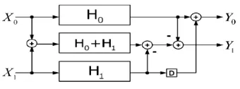
However, (4) can be written as
(5)
[image:2.595.312.514.458.575.2]Implementation of (5) is shown in Fig. 2. This structure has three FIR sub-filter blocks of length N/2, which requires 3N/2 multipliers and 3(N/2 − 1) + 4 adders. From the figure, this filter structure has one preprocessing and three post-processing adders [3].
Fig. 1. Traditional 2-Parallel FIR Filter
Fig. 2. Two-Parallel FIR Filter Implementation using FFA
[image:2.595.317.487.593.656.2]Where h(0)=h(23), h(1)=h(22), h(2)=h(21), h(3)=h(20), h(4)=h(19)
h(5)=h(18)…….h(11)=h(12),applying to proposed two parallel FIR filter structure, and the top two sub filter blocks will be as H0±H1={h(0)±h(1) h(2)±h(3) h(4)±h(5)
h(6)±h(7)…… h(18)±h(19) h(20)±h(21) h(22)±h(23)} h(0)±h(1)= ±(h(22)±h(23))
h(2)±h(3)= ±(h(20)±h(21))
h(4)±h(5)= ±(h(18)±h(19))
h(6)±h(7)= ±(h(16)±h(17))………
As can be seen from example above, two of three sub filter blocks from the proposed two parallel FIR filter structure,H0-H1 and H0+H1,are with of the symmetric coefficient now, which means the sub filter block can be realized by fig:4,with only half of the amount of multipliers required. Each output of multipliers responds to two taps. No that the transposed direct form FIR filter is employed. Compare to the existing FFA two parallel FIR filter structure, the a proposed FFA structure leads to one more sub filter block which contain symmetric coefficient. However its come with the price of the increase amount of address in preprocessing and post processing blocks. In this case two additional address are required for L=2.
2.2. 3 × 3 (L = 3) FFAs
The (3×3) FFA produces a parallel filtering structure of block size 3. From (2) with L = 3,
(6) Direct implementation of (6) computes a block of 3 outputs using 9 length N/3 FIR filters and 6 post-processing additions, which requires 3N multipliers and 3N −3 adders. By a similar approach as in (2×2) FFA, following (3×3) FFA is obtained,
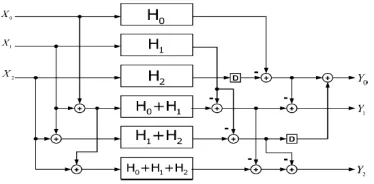
(7)
The hardware implementation of requires six length N/3 FIR sub-filter blocks, three preprocessing and seven post-processing adders, which reduce hardware cost.
[image:3.595.318.505.289.381.2]
Figure 3. Three-Parallel FIR Filter Implementation using FFA
3. PROPOSED FFA STRUCTURES FOR SYMMETRIC CONVOLUTIONS
A new structure is proposed to utilize the symmetry of coefficients. Poly-phase decomposition is manipulated to earn many sub-filter blocks, which contain the symmetric coefficients. So half the number of multiplications can be reused in the sub-filter block for the multiplication of whole taps. Therefore, for an N-tap L-parallel FIR filter the total amount of saved multipliers is half the number of multiplications in a single sub-filter block (N/2L).
3.1.2×2 Proposed FFA (L = 2)
From (4), A two-parallel FIR filter can be written as
(8)
FFA parallel FIR filter. Fig. 4 shows implementation of the proposed two-parallel FIR filter. Proposed two-parallel FIR filter structure has three sub-filter blocks. Among those, two sub-filter blocks (H0 ̶ H1 ) and (H0 + H1 ) are equipped with symmetric coefficients. So each output of multiplier responds to two taps. Compared to the existing FFA two-parallel FIR filter structure, the proposed FFA structure requires only half the amount of multipliers.
Proposed two-parallel FIR filter structure has three sub-filter blocks. Among those, two sub-filter blocks (H0 ̶ H1 ) and (H0 + H1 ) are equipped with symmetric coefficients can be realized by Fig. 5. So each output of multiplier responds to two taps. Compared to the existing FFA two-parallel FIR filter structure, the proposed FFA structure requires only half the amount of multipliers.
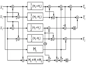
3.2.3×3 Proposed FFA (L=3)
Same as (6), a three parallel FIR filter can be written as (9). Four of six sub-filter blocks from the proposed three-parallel FIR filter structure are with symmetric coefficients. But the existing three parallel FIR filter structure has only two out of six sub-filter block with symmetric coefficients. Implementation of proposed three-parallel FIR filter structure.
COMPARISON BETWEEN PROPOSED AND EXISTING FIR FILTER STRUCTURE
Comparison between proposed and existing three-parallel FIR filter structure. Where the sub-filter blocks with symmetric coefficients shown by shadow blocks. The proposed structure additionally adds two adders in preprocessing and five adders in post processing blocks. Therefore, N/3 multipliers can be saved for proposed N-tap three-parallel FIR filter structure.
(9)
[image:4.595.297.529.80.501.2]
Fig.4. Proposed Two-Parallel FIR Filter Implementation
[image:4.595.316.503.596.737.2]Fig. 6. Proposed three-parallel FIR filter implementation
Fig. 7. Comparison of sub-filter blocks between existing FFA and the proposed FFA three-parallel FIR
structures
3.3.Proposed Cascading FFA
The proposed parallel FIR filter structure brings more adder cost in preprocessing and post-processing blocks. It reuses the multipliers in some part of the sub-filter blocks. For larger parallel block factor L, cascading the proposed FFA parallel FIR structures increase the number of adders. So hardware complexity can be increased.
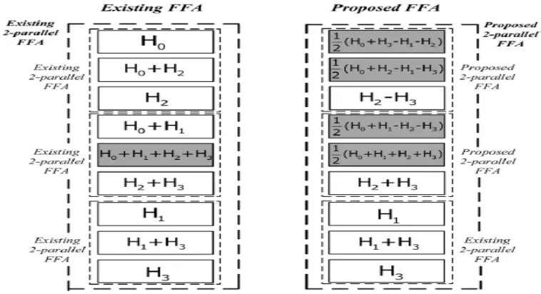
To avoid complexity, the existing FFA structures are employed for some sub-filter blocks that contain no symmetric coefficients which have more compact operations in preprocessing and post-processing blocks and the proposed FFA structures are applied to the rest of sub-filter blocks with symmetric coefficient. Comparison of sub-filter blocks between four parallel existing FAA and proposed FAA is shown.
[image:5.595.98.477.408.614.2]The proposed four parallel FIR structure has three more sub-filter blocks containing symmetric coefficients than the existing FAA structure.
Fig.8. Comparison of sub-filter blocks between existing FFA and the proposed FFA four-parallel FIR structures
4. EXPERIMENTAL RESULT AND IMPLEMENTATION
The existing FFA structures and the proposed FFA structures are implemented in VHDL with word length 16-bit and filter length of 24. Carry save, carry select and binary to excess 1 adder are used to implement the sub-filter block. Simulation
Fig. 9. Simulation Result of Parallel FIR Filter
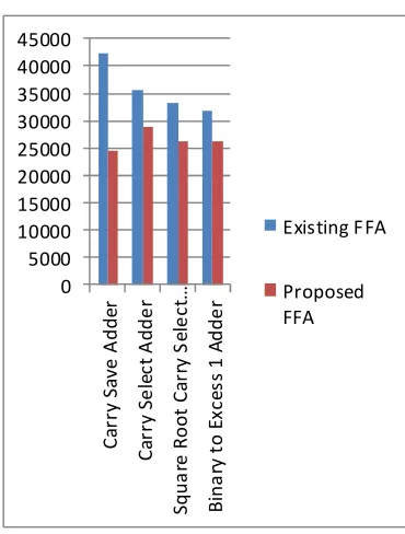
Table 1 Comparison of Area
Between Existing FFA and Proposed FFA
0 5000 10000 15000 20000 25000 30000 35000 40000 45000 C a rr y S a v e A d d e r C a rr y S e le c t A d d e r S q u a re R o o t C a rr y S e le c t… B in a ry t o E x c e s s 1 A d d e r
Existing F FA
Proposed FFA
Length Struct
ure Area Carry Save Adder Carry Select Adder Square Root Carry Select Adder Binary to Excess 1 Adder 24-tap (L=2) Existi ng FFA
42417 35502 33369 31881
24-tap (L=2)
Propo sed FFA
24437 28853 26282 26264
24-tap (L=4)
Existi ng FFA
78587 77333 74791 78407
24-tap (L=4)
Propo sed FFA
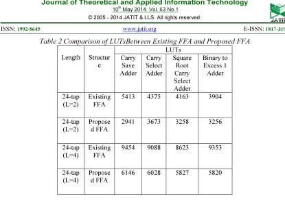
Table 2 Comparison of LUTsBetween Existing FFA and Proposed FFA
Length Structur e
LUTs Carry
Save Adder
Carry Select Adder
Square Root Carry Select Adder
Binary to Excess 1 Adder
24-tap (L=2)
Existing FFA
5413 4375 4163 3904
24-tap (L=2)
Propose d FFA
2941 3673 3258 3256
24-tap (L=4)
Existing FFA
9454 9088 8623 9353
24-tap (L=4)
Propose d FFA
6146 6028 5827 5820
Table 3 Comparison of DelayBetween Existing FFA and Proposed FFA
Length Structure
Delay(ns) Carry
Save Adder
Carry Select Adder
Square Root Carry
Select Adder
Binary to Excess 1 Adder
24-tap (L=2)
Existing FFA
34.849 34.849 34.849 34.849
24-tap (L=2)
Proposed FFA
37.109 33.905 36.080 36.190
24-tap (L=4)
Existing FFA
34.849 34.849 34.849 34.849
24-tap (L=4)
Proposed FFA
[image:7.595.151.446.403.614.2]37.584 37.135 38.486 38.659
Table 4 Comparison of Power Between Existing FFA and Proposed FFA
Length Structure
Power (mw)
Carry Save Adder
Carry Select Adder
Square Root Carry Select Adder
0 500 1000 1500 2000 2500 3000 3500
Existing FFA
[image:8.595.82.514.82.393.2]Proposed FFA
Table 5 Comparison of Maximum Frequency
Between Existing FFA and Proposed FFA
Length Structure Maximum Frequency(MHZ)
Carry Save Adder
Carry Select Adder
Square Root Carry Select
Adder
Binary to Excess 1 Adder
24-tap (L=2)
Existing FFA 79.73 129.336 137.988 120.525
24-tap (L=2)
Proposed FFA 59.96 137.912 125.188 137.912
5. CONCLUSION
Thus, a new parallel FIR filter structure was designed in order to reduce the hardware complexity and power consumption, which are beneficial to symmetric convolutions when the number of taps is multiple of 2 or 3. In parallel FIR filter implementation, multipliers are the major portions in hardware consumption. This structure uses the nature of symmetric coefficients and saves a significant amount of multipliers at the expense of adders. It is profitable to exchange multipliers with adders. Overall, the new proposed FIR filter structures consisting of advantageous poly-phase decompositions dealing with symmetric convolutions, which is better than existing FFA structures in terms of hardware consumption.
REFERENCES
[1] Basant K. Mohanty, Somaya Al-Maadeed, Pramod K Meher, Abbes Amira. Memory Footprint Reduction for Power Efficient Realization of 2-D Finite Impulse Response Filters, IEEE Transactions on Circuit Systems I, vol. 61, no. 1, pp. 120-133, January 2014. [2] Basant K. Mohanty, Pramod K Meher A
High Performance Energy Efficient Architecture for FIR Adaptive Filter based on New Distributed Arithmetic Formulation of Block LMS Algorithm, IEEE Transactions on Signal Processing, Vol. 61, no. 4, pp. 921 – 932, February 15, 2013.
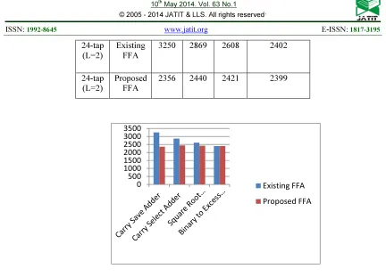
24-tap
(L=2)
Existing FFA
3250 2869 2608 2402
24-tap (L=2)
Proposed FFA
[3] Zhen Gao, Pedro Reviriego, Wen Pan, Zhan Xu, Ming Zhao, Jing Wang and Juan Antonio Maestro, Efficient Arithmetic Residue Based SEU Tolerant FIR Filter Design, IEEE Transactions on Circuit Systems II: Express Briefs, Vol. 60, No. 8, pp.no. 497 – 501, August 2013.
[4] Shen Fu Hsiao, Jun Hong Zhang Jian and Ming Chih Chen, Low Cost FIR Filter Designs Based on Faithfully Rounded Truncated Multiple Constant Multiplication/ Accumulation, IEEE Transactions on Circuit Systems II: Express Briefs, Vol. 60, No. 5, pp.no. 287 – 291, May 2013.
[5] I.Kouretas and V.Paliouras Delay Variation tolerant FIR filter architectures based on the Residue Number System, IEEE, 2013.
[6] Yu-Chi Tsao, Ken Choi. Area-Efficient Parallel FIR Digital Filter Structures for Symmetric Convolutions based on Fast FIR Algorithm. IEEE Transactions on Very Large Scale Integration (VLSI) Systems Vol. 20, No. 2, pp. 366-371, February 2012.
[7] Acha, J.I. (1989). Computational structures for fast implementation of L-path and L-block digital filters. IEEE Transactions on Circuit Systems I, vol. 36, no. 6, pp. 805–812. [8] Cheng C, Parhi K.K. (2004). Hardware
efficient fast parallel FIR filter structures based on iterated short convolution. IEEE Transactions on Circuits Systems I, Reg. Papers, vol. 51, no. 8, pp. 1492–1500.
[9] Cheng C, Parhi K. K. (2005). Further complexity reduction of parallel FIR filters. in Proc. IEEE International Symposium on Circuits Systems I, Kobe, Japan.
[10] Cheng C, Parhi K.K. (2007). Low-cost parallel FIR structures with 2-stage parallelism. IEEE Transactions on Circuits Systems I, Reg. Papers, vol. 54, no. 2, pp. 280–290.
[11] Chung J.G, Parhi K.K. (2008). Frequency-spectrum- based low-area low-power parallel FIR filter design. EURASIP J. Appl. Signal Process.
[12] Lin I.S, Mitra S.K (1996). Overlapped block digital filtering. IEEE Transactions on Circuits Systems II, Analog Digital Signal Processing, vol.43, no. 8,pp. 586–596.
[13] Mou Z.J, Duhamel P. (1991). Short-length FIR filters and their use in fast non-recursive filtering. IEEE Transactions on Signal Processing, vol. 39, no.6, pp.1322– 1332.
[14] Parker D.A, Parhi K.K.(1997). Low-area/power parallel FIR digital filter implementations. J. VLSI Signal Processing and Systems, vol. 17, no. 1, pp. 75–92. [15] Parhi, K.K. (1999), VLSI Digital Signal