ISSN Online: 2329-3330 ISSN Print: 2329-3322
DOI: 10.4236/jfcmv.2018.61005 Jan. 31, 2018 48 Journal of Flow Control, Measurement & Visualization
Scanning PIV Method and Its Application to the
Calorimetry of Ground Source Heat Pump
Systems
Shumpei Funatani, Shinya Amano, Tetsuaki Takeda, Koji Toriyama
Department of Mechanical Engineering, University of Yamanashi, Kofu, Japan
Abstract
Ground source heat pump (GSHP) systems that use a direct expansion method are expected to have higher energy-saving performance than conventional air conditioning systems. The heat transfer rate is evaluated by measuring the temperature, humidity, and flow rate at the indoor unit of the GSHP system. However, it is difficult to evaluate the flow rate by measuring the flow velocity distribution at the outlet of the indoor unit. In this study, the Scanning PIV method is proposed to improve the accuracy of the flow rate measured by hot wire anemometers. The flow rates obtained by the hot wire anemometers were 60.6% and 15.2% higher than those from the PIV method during cooling and heating operation, respectively. Compensation formulas are generated using the results of the Scanning PIV method to correct the measurements from the hot wire anemometers. This compensation formula reduced the error gener-ated by the nonuniformity of velocity distribution. It was 60.6% to 2.5% in cooling operation and 15.2% to 0.9% in heating operation, respectively. The compensation formulas were applied to evaluate the performance of a GSHP system, and the result shows that the GSHP system provides improved per-formance stability compared to traditional air conditioning systems.
Keywords
Scanning PIV, Calorimetry, Geothermal Heat Pump System
1. Introduction
Recently, geothermal energy has attracted attention as a renewable natural energy source. Underground temperatures are stable throughout the year, being lower than the air temperature in summer and higher than it in winter. Thus, the How to cite this paper: Funatani, S.,
Amano, S., Takeda, T. and Toriyama, K. (2018) Scanning PIV Method and Its Ap-plication to the Calorimetry of Ground Source Heat Pump Systems. Journal of Flow Control, Measurement & Visualiza-tion, 6, 48-55.
https://doi.org/10.4236/jfcmv.2018.61005
Received: August 4, 2017 Accepted: January 3, 2018 Published: January 31, 2018
Copyright © 2018 by authors and Scientific Research Publishing Inc. This work is licensed under the Creative Commons Attribution International License (CC BY 4.0).
DOI: 10.4236/jfcmv.2018.61005 49 Journal of Flow Control, Measurement & Visualization ground source heat pump (GSHP) has superior energy-saving performance. In conventional GSHPs, antifreeze liquid is used as the heat exchange medium that flows underground. The heat exchange between the antifreeze liquid and the ground soil is proportional to temperature difference between them, so the per-formance of the heat exchanger is strongly influenced by any heat losses. There-fore, the depth of the borehole must be over 100 m, which increases the initial cost of a GSHP system [1]. In contrast, GSHP systems that use the direct expan-sion method are expected to have higher energy-saving performance than con-ventional GSHPs [2]. In GSHPs using the direct expansion method, the refrig-erant (Freon) flows through copper tubes between the indoor unit and the derground heat exchanger. This system performs direct heat exchange with un-derground soil. Therefore, the depth of the borehole can be shortened from 100 m to 30 m, yet the performance of these GSHP systems is expected to be higher than that of conventional GSHP systems.
The heating/cooling performance of conventional air conditioning systems is measured using the air enthalpy method [3], which requires installing the air conditioning system in a large facility. This evaluation method is not applicable to GSHP systems because they are installed underground. Therefore, we evalu-ated the heat transfer rate by measuring the enthalpy difference of the air within the indoor unit of the GSHP system. The enthalpy was obtained by measuring the temperature, flow rate, and humidity at the inlet and outlet of the indoor unit. Hot wire anemometers were installed for flow rate measurement [2] and the flow rate is calculated as the product of the velocity by hot wire anemometer and the area of the outlet. In this calculation, the velocity distribution is regarded to be uniform. However, the flow velocity distribution on the outlet of the in-door unit is not uniform and it generates the measurement error.
To measure the flow distribution on the outlet of the indoor unit (y: direction of the main flow), stereoscopic particle image velocimetry (Stereo PIV) can be applied to measure the velocity field of the outlet and x-z plane is selected as visu-alized area of PIV to measure whole flow field. However, the precision of velocity measurement in y-direction is expected to be lower than x- and z-direction—the precision in the normal direction is worse than in parallel direction [4]. The scan-ning PIV method was proposed to measure the three-dimensional (3-D) velocity field, and y-z plane can be selected as measurement plane [5][6]. Velocity fields in x-direction can be evaluated by 3D reconstruction. However, the scanning speed is restricted by the flow velocity and the frame rate of the camera. Fur-thermore, it is necessary to inject fogging liquid to generate smoke for the flow visualization of PIV, which restricts measurement time. Therefore, a combined measurement method must be developed using the hot wire anemometer and scanning PIV method.
DOI: 10.4236/jfcmv.2018.61005 50 Journal of Flow Control, Measurement & Visualization improve the measurement accuracy of the flow rate. The relationships between the flow rate measured by the anemometers and the PIV were applied to evalu-ate the time variation of the coefficient of performance (COP) of the GSHP sys-tem.
2. Experimental Apparatus and Procedure
[image:3.595.160.542.460.720.2]The GSHP system consists of the heat pump and the air/refrigerant heat ex-changer replaced by the borehole-type underground heat exex-changer made with copper tubes. A four-way valve changes the circulating direction of the refriger-ant when the operation mode is changed. The underground heat exchanger comprises two long pipes connected by a U-shaped fitting at the bottom of a bored hole. The borehole is 165.2 mm in diameter and 30 m in depth. Com-pressor oil was mixed with 10.0 kg of R410A serving as refrigerant. The power of the indoor unit is 2.8 kW in cooling operation and 4.0 kW in heating operation. The heat transfer area of the air conditioner is 17.4 m2. The preset temperature is 23˚C in cooling operation and 24˚C in heating operation.
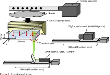
Figure 1 shows the experimental setup of the Scanning PIV system. A
rec-tangular duct was installed at the outlet of the indoor unit. The cross-sectional area of air in the outlet of the duct is 0.0495 m2. Two thermometers (Pt100: class A), two hygrometers, and four hot wire anemometers were installed in the in-door unit. These hot wire anemometers have temperature compensator units to compensate the influence of atmosphere temperature to the measurement value of hot wire anemometers. The temperature and humidity were measured at the inlet and outlet of the indoor unit. The flow velocity was measured at the outlet duct. We used the smoke generator and a diode-pumped solid-state (DPSS) laser
DOI: 10.4236/jfcmv.2018.61005 51 Journal of Flow Control, Measurement & Visualization (wavelength: 532 nm, beam power: 1000 mW) for illumination of air flow. The laser beam was expanded using a Powell lens (beam width: 1.4 mm, fan angle: 1˚). The smoke generator supplies smoke through the inlet of the indoor unit. The diode laser illuminate particle of smoke at the outlet of the indoor unit. The high-speed camera (frame rate: 2000 fps, resolution: 640 × 480 pixels, field of view: 107 mm × 80 mm) takes pictures of the illuminated particles. The diode laser and the high-speed camera were installed on a traversing device. The posi-tion of the diode laser and the high-speed camera traverse the measurement plane at 150 mm/s constantly. Therefore, 8800 visualized images were recorded over 4.4 s, and the interval between each visualized area was 0.075 mm, as shown
in Figure 2. Thus, the contiguous images overlapped for 95% of each visualized
area, so the PIV method could be applied to contiguous images. The direct cross-correlation method was selected as the analytical algorithm for the PIV method. The rotation rate of the blower of the indoor unit was fixed during the measurement.
In this study, the COP was used for performance evaluation of the GSHP us-ing direct expansion method. The flow rate and COP can be calculated as fol-lows,
Q=Av (1)
COP=Q W = ∆h Av Wρ = ∆h V Wρ (2)
[image:4.595.217.527.427.705.2]Q: quantity of heat [kW], W: power consumption of the compressor, Δh: spe-cific enthalpy at inlet and outlet of indoor unite [kJ/kg], ρ: air density [kg/m3], A: cross sectional area of air in outlet of the duct [m2], v: flow velocity [m/s], Q: flow rate [m3/s], respectively. The flow velocity v at the outlet of the duct in the indoor unit is always measured by the four hot wire anemometers and these four
DOI: 10.4236/jfcmv.2018.61005 52 Journal of Flow Control, Measurement & Visualization measured velocity data were averaged. The scanning PIV method is used to evaluate the flow rate Q′ generated from the integration of the flow distribu-tion. It can compensate the flow rate Q generated from the averaged value of 4 points of anemometers using the compensation formula Q′ = f(Q). The ex-perimental procedures of this PIV method are performed as follows:
1) The smoke generator supplies smoke to the inlet of the indoor unit; the smoke exits through the outlet duct.
2) The diode laser illuminates the particles of smoke at the outlet of the duct. 3) The high-speed camera takes pictures of the illuminated particle.
4) The diode laser and the camera traverse to the end of the duct.
5) The analytical software analyzes the particle pictures; the flow velocity dis-tribution is analyzed.
3. Results and Discussion
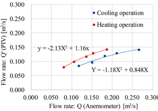
Figure 3 compares the flow rate measured by the hot wire anemometer and
[image:5.595.245.498.531.709.2]scanning PIV method during cooling operation. It shows that the flow rate cal-culated by the anemometer was higher than that from the PIV during heating (60.6%) and cooling (15.2%) operations. This occurred because the anemome-ters were installed at the center of the outlet, so the influence of the low velocity near the boundary was not reflected. The trend of heating operation was similar to that of cooling operation, but the flow rates were different between cooling and heating operation because the rotation speed of the cross-flow fans and the direction of the blades are different.
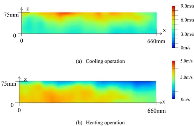
Figure 4 shows the velocity distribution at the outlet of the indoor unit of
GSHP system to show the nonuniformity of the flow. The velocity distribution was measured by traversing a hot wire anemometer (0 < x < 660 mm, y = 0, 0 < z < 75 mm, 30 seconds averaged). The rotation rate of the blower of the indoor unit was fixed during the traversing. It shows that the velocity distribution is different during each operating mode because the direction of the guide vanes was upper in cooling operation and lower in heating operation. These directions
DOI: 10.4236/jfcmv.2018.61005 53 Journal of Flow Control, Measurement & Visualization Figure 4. Contour map of the absolute value of velocity at the outlet of the indoor unit (y = 0 mm).
were set to improve the uniformity of room temperature. Therefore, the com-pensation formulas between the anemometer and PIV are evaluated for each operating mode. The compensation formulas were obtained using the least squares method:
2
1 2
Q′ =a Q +a Q (3)
a1 = −1.18, a2 = 0.848 in cooling operation. a1 = −2.13, a2 = 1.16 in heating opera-tion. The flow rates measured using anemometers were successfully compen-sated by applying these formulas. Therefore, we were able to measure the flow rate of the indoor unit for a long time with high accuracy. The average differ-ences between the compensated flow rate and the flow rate by the PIV method were 0.8% in cooling operation and 2.5% in heating operation, respectively. These are generated from the error of curve fitting of least square method. It shows that the difference is smaller than the uncertainty of velocity measure-ment and the secondary expression is enough for the curve fitting. Therefore, hot wire anemometers can be used to continuously evaluate the flow rate of the GSHP system with the same level of accuracy as the scanning PIV method.
Figure 5 shows the time variation of the COP of the GSHP system during
DOI: 10.4236/jfcmv.2018.61005 54 Journal of Flow Control, Measurement & Visualization Figure 5. Time variation of COP (cooling operation).
system will contribute not only enhanced energy generation, but also enhanced electrical capacity stability.
4. Conclusion
The scanning PIV method was proposed to measure the flow rate distribution through the indoor unit of a GSHP system. The flow rate measured by the scan-ning PIV method was used to compensate for the flow rate measured by hot wire anemometers. The compensation formula was successfully evaluated, and it re-duced the error generated by the nonuniformity of velocity distribution (60.6% to 2.5% in cooling operation and 15.2% to 0.9% in heating operation). This measurement method was applied to evaluate the time variation of the COP of a GSHP system. The results show that the COP was much higher than a conven-tional air conditioning system, and it was stable throughout the day.
Acknowledgements
This work was supported by JKA and its promotion funds from AUTORACE (28-162).
References
[1] Ohashi, A., Takeda, T. and Funatani, S. (2014) Study on Heat Exchange Perfor-mance of Ground Source Heat Pump System. Proceedings of the 25th International Symposium on Transport Phenomena, Krabi, 5-7 October 2014, Paper No. 28. [2] Takeda, T., Yokoyama, D., Ohashi, A., Ishiguro, S., Funatani, S. and Ichimiya, K
(2014) Experimental Study of Ground Source Heat Pumps That Use the Direct Ex-pansion Method. Proceedings of the 15th International Heat Transfer Conference, Kyoto, 10-15 August 2014, Paper No. 8940.
[3] ISO 5151 (2017) Non-Ducted Air Conditioners and Heat Pumps—Testing and Rating for Performance.
[4] Adrian, R. and Westerweel, J. (2010) Particle Image Velocimetry. Cambridge Uni-versity Press, New York.
DOI: 10.4236/jfcmv.2018.61005 55 Journal of Flow Control, Measurement & Visualization Strongly Buoyant Jet. Journal of Visualization, 13, 203-211.
https://doi.org/10.1007/s12650-010-0027-0
[6] Watanabe, R., Gono, T., Yamagata, T. and Fujisawa, N. (2015) Three-Dimensional Flow Structure in Highly Buoyant Jet by Scanning Stereo PIV Combined with POD Analysis. International Journal of Heat and Fluid Flow, 52, 98-110.
https://doi.org/10.1016/j.ijheatfluidflow.2014.12.003
Nomenclature
A: Cross sectional area of air in outlet of the duct [m2] COP: Coefficient of performance of the heat pump [-]
∆h: Specific enthalpy at inlet and outlet of indoor unite [kJ/kg]
Q: Flow rate of the outlet of the indoor unit estimated by anemometer [m3/s] Q′: Flow rate of the outlet of the indoor unit compensated using scanning PIV [m3/s]
v: Averaged flow velocity [m/s]
x, y, z: Cartesian coordinates defined on the outlet of the indoor unit
W: Power consumption of the heat pump system [W]