FOR AUTOMATIC ASSEMBLY
A thesis presented for the degree of Doctor of Philosophy in Mechanical Engineering
at the
University of Canterbury, Christchurch, New Zealand
by
C. H. H. WOHLERT-JENSEN
ACKNOWLEDGEMENTS
My sincere thanks to my supervisor Professor H. McCallion for his guidance and encouragement.
I also extend my gratitude to Professor D. C. Stevenson for the use of the Departmental facilities and to other academic and technical staff, in particular, Messrs. G. Johnson, E. Retallick and 0. Bolt.
The objective of the research work carried out was the development of techniques useful in automated assembly. In particular, methods were sought which would allow the extension of simple robot capabilities from the "pick and place" function to the less ordered domain of assembly. Three approaches towards correcting the gross misalignment of a peg and hole are described.
An established method of facilitating assembly involves the vibration of the contacting misaligned components. This technique was studied with respect to the behaviour of an elastically constrained peg under the action of a rotating force. The study was limited initially to a relatively straightforward analysis of simplified situations, then, in order to allow the prediction of the behaviour of practical systems a program was developed which simulated the behaviour of a general nine degree-of-freedom assembly system.
This work led to the second approach where the possibility of using the vibrational motion of the contacting components as feedback for position sensing was investigated.
The third technique involved determining the spatial relationship between the components on the basis of contact forces sensed in their respective coordinate systems.
CONTENTS
ACKNOWLEDGEMENTS ABSTRACT
CHAPTER ONE - Introduction
CHAPTER TWO - Perspectives 2.1
2.2
Technical Perspective Social Perspective
CHAPTER THREE - The Assembly Process_ 3.1
3.2
3.3 3.4
PART ONE
The Assembly Process Peg-Hole Contact
3.2.1 Peg Edge -Hole Edge Single Point Contact 3.2.2 Peg Edge - Hole Edge Double Point Contact 3.2.3 Peg Edge - Hole Plane Single Point Contact Impact During Assembly
Friction During Assembly
CHAPTER FOUR - Vibratory Assembly Vibratory Assembly
Vibratory Assembly Device 4.1
4.2 4.3 4.4
Peg Edge - Hole Edge Single Point Contact with no Sliding
4.5 4.6
Peg Edge
-
Hole Edge 4.4.1 Single Point 4.4.2 Single Point Peg Edge - Hole Edge Peg Edge-
Hole EdgeSingle Sliding Sliding Double Double
Point Contact with Sliding Solid Cylindrical Peg h>>r Solid Cylindrical Peg r>>h Point Contact with no Sliding Point Contact with Sliding
4.7 Peg Edge- Hole Edge Double Point- Single Point
4.8
4.9
Contact with no Sliding
4.7.1 Equations of Motion for Double Point Contact 4.7.2 Equations of Motion for Single Point Contact 4.7.2.1 Transformation of Rotations About Principal
Axes 4.7.3 Total Solution
Peg Edge - Hole Edge - Hole Plane Contact
4.8.1 Equations of Motion for Peg Edge - Hole Edge Contact
4.8.2 Equations of Motion for Peg Edge - Hole Plane Contact
4.8.3 Total Solution Summary
CHAPTER FIVE - Vibratory Assembly Test Rig 5.1 Vibratory Assembly Test Rig
5.2 Theoretical Analysis 5.3 Experimental Work 5.4 Results
5.5 Discussion 5.6 Conclusion
CHAPTER SIX - Computer Simulation of an Assembly System. 6.1
6.2
Simulation of an Assembly System 6.1.1 System Generalized Coordinates 6.1.2 Coordinate System Transformation 6.1.3 System Inertias and Masses
6.1.4 System Stiffnesses and Damping 6.1.5 System Forces and Moments Equations of Motion
6.2.1 Kinetic Energy
6.3
6.2.2 Potential Energy 6.2.3 Energy Dissipation
6.2.4 Applied Forces and Moments
6.2.5 General Form of Lagrange's Equation Solution of Equations of Motion
6.3.1 Peg- Hole Contact
6.3.1.1 Location of Contact Points 6.3.1.2 Velocity of Contact Points 6.3.1.3 Misalignment Modes
6.3.2 Contact Forces 6.3.2.1 First Approach 6.3.2.2 Second Approach
CHAPTER SEVEN - Program Description and Evaluation 7.1
7.2
7.3
Computer Programs Program Evaluation 7.2.1 Impact 7.2.2 Sliding Summary
CHAPTER EIGHT - Simulation Results 8.1
8.2
8.3
8.4
System Parameters Coupling Stiffness 8.2.1 Results Coupling Damping 8.3.1 Results
Exciting Force Magnitude 8.4.1 Results
8.5 Contact Force 8.5.1 Results
8.6 Rotation of Exciting Force 8.6.1 Results
8.7 Summary
PART TWO
CHAPTER NINE - Vibratory Position Sensing 9.1 9.2 9.3 9.4 9.5 9.6 9.7 9.8 9.9
Vibratory Assembly Device with Motion Sensing Single Point Contact with no Sliding
9.2.1 Symmetrical Constraint Stiffnesses 9.2.2 Low Transverse Constraint Stiffnesses 9.2.3 Low Vertical Constraint Stiffness Single Point Contact with Sliding
Double Point Contact with no Sliding Double Point Contact with Sliding Triple Point Contact
Summary, Peg Movement Under Various Contact Conditions
9. 7 .1. Assembly Strategies Based on Vibration Single Point Contact Assembly Strategy
Loci
9.8.1 Single Point Peg Edge - Hole Plane Contact 9.8.2 Single Point Peg Edge - Hole Edge Contact 9.8.3 Single Point Assembly Algorithm
Double Point Contact Assembly Strategy
9.9.1 Double Point Peg Edge - Hole Edge Contact 9.9.2 Double Point Assembly Algorithm
139 139 148 148 148 154 155 155 155 157 159 159 160 160 162 162 162 164 164 164 167 169 169 169 173 9.10 Experimental Assessment of Vibratory Motion as Feedback 173
9.10.2 Experimental Work 9. 11 Summary
PART THREE
CHAPTER TEN - Twin Force Sensor Position Sensing 10.1
10.2 10.3 10.4 10.5
Twin Force Sensor Position Sensing Determination of Rotation Tensor Determination of Translation Tensor Error Analysis
Summary
PART FOUR
CHAPTER ELEVEN - Six Degree-of-Freedom Force-Displacement Sensor 11.1 11.2 11.3 11.4
ll.5
11.6 11.7Force and Displacement Sensor Design Final Sensor Design
Sensor Coordinate System
Displacement - Strain Transformation Force-Strain Transformation
Moment-Strain Transformation Summary
CHAPTER TWELVE - Summary of Work 12.1
12.2
Summary of Work Future Work.
APPENDIX 1
APPENDIX 2
INTRODUCTION
The majority of robots on todays industrial scene are open-loop devices operating in either "point to point" or "continuous motion" modes. The manipulative skills of these robots may be extended by the addition of job-oriented hardware, such as locating pegs, chamfers, or vibrators, or by the incorporation of a sensor-driven feedback loop.
approaches are used in this thesis.
Both these
Initially, however, the field of robotics is surveyed from both a technical and a social point of view. The technical aspect provides a frame of reference for the content of the thesis. The social view uses, figuratively speaking, a wide angle lens to examine the common justific-ations for the robot.
In Chapter 3 the general problem of assembly is sketched out and · the peg-hole configuration is defended as a case for further study. Work on the geometric and physical interactions of this configuration completes the Chapter and provides a foundation for following work.
Chapters 4 to 8 are grouped together to form Part 1. Here the use of vibrations as a method of facilitating assembly is considered.
In Chapter 4 simple analytic analyses of vibratory assembly are performed to determine the basic conditions under which assembly may occur.
Chapter 4 deals with simplified situations; assembly modes are examined in isolation and simple constraints are used. As the assembly process in general is characterized by a wide range of misalignment modes, a full analytical solution would involve an analysis and determination of the limits of application and boundary conditions of each mode. Also
more complex manipulator constraints lead to off-diagonal terms in stiffness and damping matrices, complicating analytical solutions. Hence i t was decided to use a computer simulation to provide a method whereby the general principles found in Chapter 4 could be employed in the design situation.
The equations of motion of a general nine degree-of-freedom assembly mechanism are developed and two methods of solution described in Chapter 6.
The behaviour of the resulting computer programs is evaluated in Chapter 7 by comparing simulated results with analytical solutions of particular cases.
In Chapter 8 the final program is used to investigate the behaviour of a particular system.
The possibility of using the vibratory motion of components as a method of position sensing is put forward in Part 2 which contains only one chapter, Chapter 9.
this approach.
Limited experimental work indicates the feasibility of
between the sensed force and component misalignment. Essentially therefore the resulting manipulator controlling algorithms are probabilistic. The approach described in Chapter 10, in which we assume forces associated with both components may be sensed, differs in that the forces felt uniquely specify the misalignment.
Finally Part 4, Chapter 11, describes the construction and cali-bration of two 6 d.o.f. force displacement sensors suitable for either contact force or vibratory position sensing. The calibration accuracy of 6 d.o.f. force sensors is often limited by the accuracy of the
calibration loads. is described.
4
CHAPTER 2
PERSPECTIVES
A major feature of mid-twentieth century technology has been the extension of man's computing and controlling powers by electronic tech-nology and the science of cybernetics. This change has affected virtually all areas of business and industry in developed countries with general purpose computers performing data handling, computation, and control.
As the cost of machine intelligence decreases i t becomes possible to further extend the use of machines into areas of work previously occupied by humans. One large area potentially open to advanced automation is that of assembly, an activity at present absorbing the efforts of almost half the industrial workforce. In this Chapter we examine both the technical state of, and social justification for, robots.
2.1 TECHNICAL PERSPECTIVE
The scope of assembly work is immense and in this section only major areas of research and application will be mentioned.
given product family, in this case post office relays, has been success-fully developed at the University of Nottingham [3].
For less structured environments some form of feedback is necessary and a second category may be defined. These machines utilize information from tactile, sonic, or visual sensors to provide inputs to a controlling algorithm. A well known example is the Japanese Hi-T-Hand, a sequentially controlled assembly robot, with wrist force sensors, capable of assembling cylindrical components with a clearance of 20 microns [4]. The potential of visual feedback is demonstrated by a system developed at General Motors where the position of studs on an automobile hub is found from a TV picture, using pattern recognition techniques, thus allowing the wheel to be fitted
[s].
Manipulators of this type are useful provided the modes of misalign-ment are limited and the assembly motion is simple.generation systems only exist within the laboratory environment.
At the Stark Draper Laboratories efforts have been made to examine the problem of assembly from a theoretical viewpoint. At the macro level work has concentrated on a detailed analysis of the assembly sequence, tools, and jig requirements etc. [11] . The micro view deals with the mechanics of assembly, the interaction of components, and the forces and trajectories required for assembly [12].
Assuming the continuation of the present industrial order, the future development of robotic automation is likely to continue along the following paths. The improving utility of simple position controlled robots should make them an evermore attractive proposition to industry. Both modular assembly systems and more general 6 d.o.f. manipulators are contenders in this market [13]. The decreasing price and increasing power of electronic hardware should continue to stimulate the development of 2nd and 3rd generation robots [ 14] [ 15] .
2.2 SOCIAL PERSPECTIVE
Possession of the technical ability to build new machinery does not automatically justify its employment, therefore in this section we shall examine the raison d'~tre of robots in the wider context of the overall sociotechnical system.
The arguments advanced by the proponents of robotic automation may be divided into two categories. Firstly, economic grounds, often expressed in the economic concepts of cost accounting, where robots are seen as
being able to provide profitable reliable labour in an industrial scene increasingly plagued by unrest and rising labour costs. [16] [17] [1a] [19]
dangerous or monotonous work and therefore is capable of freeing workers for the more pleasant tasks of supervision, maintenance, and programming.
[1] [ 17] [22] [2 3] .
The first of these arguments is based on the assumption that the cost-benefit analysis is a sufficiently accurate method with which to judge the worth of advanced automation systems. Although convenient, and amenable to the economic calculus, this approach by necessity deals only with the readily quantifiable elements of the situation. The results,
according to Schumacher [24], are that short term costs are given vastly more weight than long term costs, and also that the free component of goods such as air, water, and raw materials is by definition excluded from the analysis. In the light of modern day environmental crises, namely pollution, energy and raw material shortages, such analyses must offer a distorted picture. Efforts to sophisticate the economic procedures, to incorporate the intangibles, are based on the premise that everything has a price, and again the conclusion fails to reflect reality.
Obviously economic analyses have an important role, however, the
fact must be realized that they are only true within a defined and artificial framework and thus can only be considered as data for a human judgement.
The second argument put forward for the robot, that of work
improvement, may be criticized on the basis of studies performed by socio-logists in automated industries since the mid-sixties.
Adam Smith in 1776 predicted that the division of labour made possible by factory mechanization would render work trivial, repetitive, and dull. This perspective has persisted until the present day where i t finds
variations of alienation which he considers relevant to people in today's industrial setting. One of these is. the powerlessness of men in modern industries where job performance is largely dictated by the system, for example in highly automated plants where men may function simply as machine minders. Another aspect of alienation is meaninglessness, this resulting from the fragmentation of the production process into small areas, thus removing the worker from the end product of his labours. Again, this separation of the worker from his work could be aggravated by the installation of robots.
Erich Fromm [26] fears that automation has isolated the worker psychologically from his colleagues; the reduction in labour requirements made possible by robots could promote a loss of camaraderie in traditionally non-automated industries. A further effect of automation has been a
general reduction in the skill demanded of the worker, according to James Bright [26] .
In a paper presented to leading British and European roboticists, M. J. Cooley [27] examines these social difficulties and concludes "These problems are widespread and growing in their generality".
Therefore, although i t is a fact that robots have eased the burden of industrial work in such areas as forging, welding, and the handling of hot or dangerous materials, i t does not automatically follow that their introduction leads to work enrichment, but possibly the reverse, unless the attendant problems are dealt with.
Thus neither of the two arguments tendered is capable of justifying the robot per se. This situation exemplifies two traps which snare
narrowness of his perceptual scale.
H. Ozbekhan, quoted by H. W. Bruck [29], describes the effects of these traps in the technological system, "Confronted with what appears inevitable, people tend to abdicate their role as creators of new and different events and abide by the dimensions and measurements which current technology has imposed upon their vision. Further, once imprisoned within such a restricted outlook they tend automatically to act so as to make the prediction come true. The present is thus perpetu-ated by techniques which become strengthened and more elaborate at each step of the way - as does the feeling of impotence and irrelevance
experienced by those who manipulate them. Technique-derived imperatives multiply and increasingly restrict the areas of free choice".
From this we must conclude that decision making, to be effective at all, must consider as many different viewpoints as possible. The decision maker is in effect called upon to assume a variety of roles,
these dictated by the decision situation. For example a factory engineer considering the installation of new plant should view the decision confront-ing him in turn through the eyes of a worker, a shareholder, a sociologist, a conservationist etc.
The difficulties of such a stance are apparent. Decision makers at all levels are constrained to conformity simply for day-to-day survival. The complexity of what H. W. Bruck [29] calls "The Great
10
THE ASSEMBLY PROCESS
In this Chapter we shall attempt to gain a closer view of the
assembly process, in particular the importance of the final fitting stage. As a prelude to further studies, the contact modes of an unchamfered peg and hole are considered, as well as the impact and friction characteristics.
3.1
THE ASSEMBLY PROCESSThe assembly process is a complex task, involving the selection, transfer, orientation, and fitting of components comprising the final product
[3o].
Whitney[31]
defines assembly as "a staged process of removal of uncertainty until positions and orientations are known with enough certainty so that assembly can occur".Robot manipulator systems in general have the functional flexibility required to cope with the wide variety of operations demanded by the
assembly process. However, because of structural deflections, wear, and limitations in positioning control, the locating accuracies are restricted to the range
1-.1
mm[31].
As the clearances existing between components may be ten times less than these limits, obviously the final stages of positioning are most critical.The study of the mechanics of assembly will be centred around the case of a peg and hole for the following
(ii) The geometric analysis is relatively straightforward and the modes of misalignments are limited.
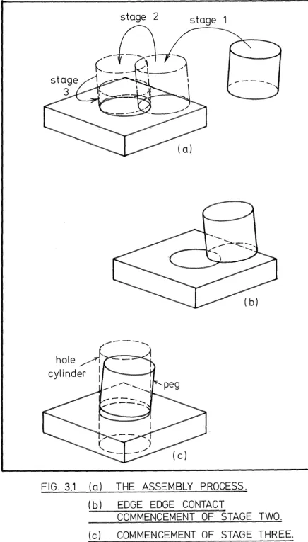
Given the peg-hole configuration we may define the assembly process more rigorously, as shown in Fig. 3.1.
(i) Stage 1 involving the transfer of the peg to the hole. This gross motion typically is achieved by the robot and will have a final position-ing error of several millimetres.
(ii) Stage 2 is defined as beginning when contact occurs between the edge of the peg, and the edge of the hole at either one or two points. This stage involves the sensing and correction of the peg position in readiness for Stage 3.
(iii) Stage 3 is the final assembly stage and in this case may conveniently be defined as beginning when the peg edge lies within the projected hole cylinder. In this stage fine manipulation is required in order to avoid jamming or wedging.
Although considerable work has been done on the insertion of a peg into a hole
[4]
[1i] [12], i.e. Stage 3, the initial positioning, Stage 2, has been a relatively neglected area considering the large number of modes of misalignment possible. Therefore in this thesis the problems associated with Stage 2 of peg-hole assembly only will be dealt with.3.2 PEG-HOLE CONTACT
FIG. 3.1
(a)
THE ASSEMBLY PROCESS.
(b)
EDGE EDGE CONTACT
COMMENCEMENT OF STAGE TWO.
[image:22.608.91.528.43.809.2]14
(i) Peg edge - hole edge single point contact. (ii) Peg edge - hole edge double point contact. (iii) Peg edge - hole plane single point contact.
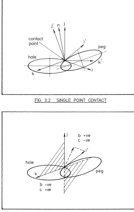
3.2.1 Peg Edge-Hole Edge Single Point Contact
Contact occurs as shown in Fig. 3.2. Limited rotation of the peg may occur about the contact point and sliding may occur on the contact plane.
McCallion and Wong [33] give the direction of the contact normal in the hole centred ijk coordinate system as
c
i
b k (3 .1)n
=
where the tangent vector i ' of the peg circumference is i ' = ai + b
i
+ c~_,and the vector i is tangential to the hole circumference.
The assumption is made that the contact normal lies in the radial planes of both peg and hole cylinders.
Because the peg edge cannot intersect the hole plane the tangent vector i ' must have components in the quadrants shown in Fig. 3.3, i.e. b +ve and c -ve, or vice versa. As a result the +ve unit normal vector always contains the component
b
k
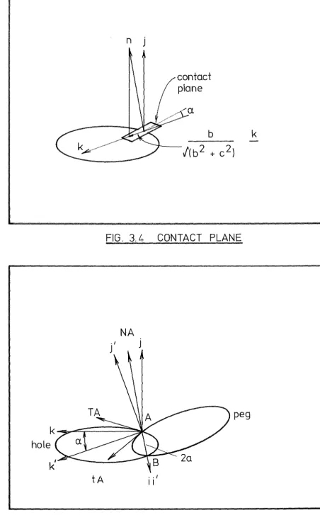
lying toward the hole centre. In other words, single point contact occurs on a plane inclined at an angle
-1
sin b
/(b2
+
c2)contact
point
n
J
• I
I
FIG. 3. 2
SINGLE POINT CONTACT
b
-ve
c +ve
J
b
+ve
c -ve
[image:24.606.87.535.54.762.2]to the horizontal, Fig. 3.4. The effect of this is that a chamfer effect exists as a result of the angular misalignment.
It may be seen from Equation 3.1 that in cases of small angular misalignment, i.e. as
b -+ 0
the normal n becomes aligned with the vertical i axis.
3.2.2 Peg Edge-Hole Edge Double Point Contact
When contact occurs at two points, A and B, as shown in Fig. 3.5, rotation may occur about the chord connecting the contact points and sliding may occur at either contact point.
With reference to Fig. 3.5, the triad of unit vectors
i
i ~ is centred at A,i
and ~ lie in the plane of the hole circumference, i being collinear with chord AB. The triadi'
i ' ~· is again centred at A and is similarly aligned with respect to the peg edge. The two coordinate systems are rotated with respect to each other by the angle a, about the AB axis, and the length of AB is 2a.The tangent vectors to the hole circle radius R at A and B may be written as
TA
V(R
2-a2) i+
a k ( 3. 3)TB i I (R 2 -a ) 2 i
+
a k (3. 4)The tangent vectors to the peg circle, radius r, transformed to the i j k system becomes
tA tB
1 2 2
hole
tA
n j
contact
plane
FIG. 3. 4
CONTACT PLANE
NA
J
peg
0 , /
II
[image:26.613.85.538.56.783.2]18
The tangent vectors of the peg and hole circumferences are
normal to their respective radial planes, hence we may write the contact normal vectors as,
NA (TA x tA) NB (TB x tB) i.e.
(3.7)
NB ( 3. 8)
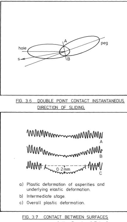
Sliding may occur on the contact planes at either A or B, so the instantaneous direction at sliding ~' without rotation, is given thusly
s NA x NB
s (3. 9)
If the peg and hole radii are equal then
s tan2
a .
2
+
k (3.10)i.e. the instantaneous direction of sliding is perpendicular to chord AB and lies midway between the peg and hole planes as shown in Fig. 3.6.
As previously, we see that for small misalignments, i.e. as a + 0
both NA and NB become aligned with
i·
3.2.3 Peg Edge~Hole Plane Single Point Contact
Impact between the component surfaces occurs during the final fitting stage and in general the contacts made will be either
i Edge - edge contact i i Edge - plane contact.
Contacts involving edges are characterized by low area and high pressures.
The commonly accepted view of contact between surfaces [34] involves the progressive plastic deformation of asperities with underlying elastic deformation, as illustrated in Fig. 3.7. In high pressure situations, such as occur during assembly, we would expect the contacts to be largely plastic.
Evidence exists suggesting that the presence of a lubricant film is capable of introducing a viscous damping component into the contact force [35].
3.4 FRICTION DURING ASSEMBLY
The friction existing between contacting components during assembly is complicated by the high local pressures causing surface deformation and mechanical locking. The results of tests carried out by Simunovic [12] are shown in Fig. 3.8. These show a considerable variation in the coefficient of friction occurring on the first sweep.
become bedded in on this run.
Presumably the components
FIG. 3.6
DOUBLE POINT CONTACT INSTANTANEOUS
DIRECTION OF SLIDING.
A
a) Plastic deformation of asperities and
underlying elastic deformation.
b) Intermediate stage.
c) Overall plastic deformation.
[image:29.608.94.530.42.802.2]0·2
~
0·1
0
0
0·2
1-1 0·1
1.
Steel on
2. Steel on
3. Steel on
4. Steel on
1
43
2
r
2R
T
R-r
C =
-50
100
150
R
N
Friction at tip of peg
- - 1
- ---4
3
- - - 2
50
100
N
150
Friction at mouth of hole
steel
c
=
-g
X10- 3
steel
c
=
9
X10- 3
steel
c
=
3
X10-3
al
c
=
3
X10-3
peg
~I
hole
- 1st sweep
FIG. 3.8
FRICTION IN PEG -HOLE CONTACTS
PART ONE
VIBRATORY ASSEMBLY
This Chapter examines the use of vibration to facilitate the
assembly process, in particular the behaviour of a simple spring-constrained peg-hole system under a periodic force.
A variety of assembly movements are studied, and the results evalu-ated with regard to practical applications.
4.1 VIBRATORY ASSEMBLY
During assembly a wide range of contact modes may occur between the mating components before the final assembled state is achieved. The contact forces existing between the components are dependent on the misalignment and therefore may, under certain circumstances, be used to aid assembly. Aligning contact forces may be produced, for example by chamfers. Contact forces aiding assembly may also be produced by the application of a periodic force.
In the initial stages of assembly the oscillatory motion of the vibrated component acts as a searching movement. This principle is used by Kar.elin & Girel
[37]
and Andreev[38],
where cylindrical parts are oscillated in a 50 Hz rotating magnetic field to find a mating recess, significant radial misalignments being dealt with. Kan.elin and Gi:r;.el [39] and Savischenko[4o]
also report successful assembly, using mechanical oscillators.ultrasonic frequencies to achieve the assembly of a peg into a hole.
The motion of a peg during vibratory assembly is complex, influenced by manipulator constraints, the exciting force and the type of contact. Consequently, a comprehensive analytical approach is difficult. However, i t is still advantageous to examine some simplified situations in order to gain insight into the possible types of behaviour.
4.2 VIBRATORY ASSEMBLY DEVICE
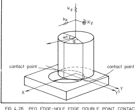
The phenomena occurring in vibratory assembly are discussed with reference to the peg-hole manipulator system shown in Fig. 4.1. The unchamfered peg, ofheight 2h, radius r, mass m is supported in elastic constraints, acting at a height 1 above its top surface. Contact between the peg and hole edges occurs at either one or two points and the peg edge may also contact the hole plane. A force of magnitude F rotates about the peg vertical axis as shown, and gravity acts at the centre of mass.
4.3 PEG EDGE - HOLE EDGE SINGLE POINT CONTACT WITH NO SLIDING
The first case to be examined is that shown in Fig. 4.2 where contact between the peg edge and hole edge occurs at a single point.
In the case where no sliding occurs the peg may be treated as an elastically-constrained body rotating about the contact point.
It is convenient to define axes 8 8 8 centred at the contact
X y Z
L
2h
FIG. 4.1
VIBRATORY ASSEMBLY DEVICE
x
y
z are
inertia axes
wt
8y
contact point
y
point. For convenience of analysis we shall assume that the three principal rotational stiffnesses are equal.
The equations of motion for small rotational movements of the peg about the
e e e
axes areX y Z
I 8
+
K8X X X
I 8
+
K8 y y yI 8
+
K8 z z zM X M y M z (4 .1) (4. 2) (4. 3)
where I I I are the moments of. inertia about the 8 8 8 axes and K
X y Z X y Z
is the rotational stiffness about those axes. The moments about the
e e e
axes due to the applied force areX y Z
M - 2Fheos (wt-a)
X
M -F(rsinS +2hcosS) sin (w·t-a) y
M -F(rcosS -2hsinS) sin(wt-a) z
(4. 4)
( 4. 5)
(4.6)
The angle
a
describes the position of the contact point on the peg edge with respect to the peg centred XYZ coordinate system. The angle between the y axis and the XY plane is S.The steady state solution of the equations of motion becomes
e
Xe
ye
z-2Fh cos (wt-a) K-I
w
2X
-F(rsinS +2hcosS) sin(wt-a) 2
K-I ul y
-F(rcosS -2hsinS) sin(wt-a) 2
K-I
w
z
(4.7)
(4. 8)
the y-z plane, Fig. 4.3.
..e_
p ( 4. 10)
Thus the resulting motion of the peg is a non-symmetric clockwise or anti-clockwise wobble about an axis Q, perpendicular to both x and P and passing through the contact point as shown in Fig. 4.3.
4.4 PEG EDGE - HOLE EDGE SINGLE POINT CONTACT WITH SLIDING
The combination of exciting force and spring force, acting approx-imately parallel to the contact plane, may cause slippage at the contact point.
In the previous section, Section 4.3, i t was shown that the symmet-rically constrained peg under the action of a rotating force executed a wobble about the axis Q through the contact point. Referring to Fig. 4.4, the movement of the constraint attachment point G in the X*Y*Z* system for small movements may be expressed in terms of the wobble displacements.
X*
=
-8 1 sinSX 2 (4.11)
Y* -8 1 sine
1 (4.12)
p
Z* -8 1 cos8
2 (4.13)
X
Assuming the transverse stiffnesses k to be equal in all directions, then clearly the peg will experience a force proportional to and opposing the displacement at G.
y
Q
FIG. 4. 3
SINGLE
POINT
CONTACT WOBBLE AXIS
Q
z*
+(Fsin(wt-a) + kl8 sin8 )
i
p l
This force is shown diagramatically in Fig. 4.5.
(4.14)
F is of constant magnitude and rotates in an anti-clockwise direction, whereas FG , which
.S
follows an elliptical path rotates either clockwise or anti-clockwise. Clearly the maximum sliding force occurs when the two force vectors are coincident.
The normal force FN is altered by the vertical constraint force FGN at G, i.e.
F
N mg- k.l.8x cos82 (4.15)
Obviously as the vertical force approaches the magnitude of the peg mass sliding will occur. If the resultant horizontal force on the peg is toward the hole at this stage, assembly will occur.
Clearly for single point contact the final motion is subject to a host of variables such as the peg dimensions, constraint stiffness and exciting force. Two simple cases will be dealt with in the following sections.
4.4.1 Single Point Sliding, Solid Cylindrical Peg h >> r For a long thin cylindrical peg, Fig. 4.6
h >> r
B
n o
From Equations 4.7- 4.9 we see that 8 is much smaller than 8
Z X
and 8 , and as a result the wobble axis Q is approximately aligned with z.
X
direction
y
direction
x*
FIG. 4. 5 FORCES ACTING ON PEG- X*
Y*
PLANE
X
____l~-?<~:::::;:,._-8x
le I
Qle I
Q 2F.h.X y K
and as a result there is a symmetrical clockwise wobble about the vertical z axis. Equation 4.14 states that the resulting reaction force FG acts
s in opposition to the applied exciting force, thus reducing the nett sliding force F .
s The normal force FN is not affected overly by the move-ment of the peg as the radius is small, Equation 4.15.
When the exciting frequency lies between the two resonant frequencies,
(!j and (l) ' of motions in the
e
ahde
direction the wobble becomesanti-x
y X yclockwise, and the spring reaction force and exciting force combine to give a high sliding force, twice per cycle. For a peg of. the dimensions con-sidered the moments of inertia, I and I , and thus the natural frequencies,
X y
w and uJ , are quite close.
X y
At high frequencies, above either W or
w ,
and also well removedX y
from the natural frequency of motion in the
e
direction, the wobble again zbecomes anti-clockwise. However as the inertia forces are now dominant, the spring constraint and exciting forces are aligned. Sliding may be likely in this case. Possibly the chamfer effect referred to in Section 3.2.1 may bias sliding toward the hole.
4.4.2 Single Point Sliding, Solid Cylindrical Peg r >> h In the case of a short cylinder
r >> h
f3 Q 0
and when the exciting frequency is not close to any of the resonant frequen-cies,
e
predominates overe ,
ande
is also small as can be seen fromy Z X
As a result the motion of the peg consists essentially of an oscillation about the vertical~ axis, Fig. 4.7.
At low frequencies the spring constraint force opposes the exciting force and above resonance,
w ,
the forces are in phase.y
Near the resonance frequency W the increased amplitude of motion
X
about the ex axis combined with the large radius of the peg will cause considerable translation movements of the spring constraint attachment point in the vertical direction. The effect of this displacement acting on the vertical constraint spring will be to cause the normal contact force to fluctuate. Sliding may occur in this case.
In the peg types considered in this and the previous section, sliding may be expected at high rather than low frequencies and the
chamfer effect described in Section 3.2.1 may then cause sliding assembly to occur.
4.5 PEG EDGE - HOLE EDGE DOUBLE POINT CONTACT WITH NO SLIDING
We will now examine the case where contact between the edge of the peg and the edge of the hole occurs at two points as shown in Fig. 4.8.
If the condition mg rsina
?
2 Fhholds, double point contact is maintained throughout the force cycle,
and if no sliding occurs the situation simplifies to a simpl~ spring-inertia system rotating about the contact chord Y' axis.
8y y
FIG. 4. 7
SINGLE POINT CONTACT r
>>
h
contact points
at
A
&
B
F
e = 2Fh coswt2 Y' ( Ky1-Iy,W
where the rotational stiffness about the Y' axis is
2 2 2
k (2h+l) +K + k r (1-cosa)
X Y Z
and the inertia is
2 . 2 2
=
~(16h
+(3+12cos a)r ) 124.6 PEG EDGE - HOLE EDGE DOUBLE POINT CONTACT WITH SLIDING
As in the single point contact case the combined exciting and
(4 .16)
(4.17)
(4 .18)
reaction forces may cause sliding. The limiting conditions for sliding will be developed below under the assumption that Equation 4.16 remains valid.
At frequencies below the natural i.e. when
the exciting moment is in phase with the peg displacement and hence the exciting force F and spring reaction force F act in opposition.
X
Consideration of the static case shows that at low frequencies, the exciting force exceeds the spring force, and therefore sliding into the hole is most likely to occur when the peg is positioned as shown in Fig. 4.9a. Recalling the previous result in Section 3.2.2, giving the instantaneous direction of sliding for a peg and hole of equal radius and ignoring the wedging effect of the peg and hole edges, we may write the surface reaction forces of the equivalent system, Fig. 4.9b, in terms of the applied forces, i.e.
F
X
a+8 a-8
mg cos (
-2-) + (F-F) sin ( -2-) . (a+8) + (F-F ) (a-e) mg sln
-2- x cos - 2
-(4.19)
>
i.e. when the coefficient of friction at the contact point is exceeded. Rewriting Equation 4.16
2 F
=
(Ky'-Iy'w )8(4.21) 2h
and from Fig. 4.9a, i t can be seen that the spring force F
=
k (2h+l)8X X (4.22)
Thus, substituting Equations 4.21 and 4.22 into Equations 4.19 and 4.20, the contact force ratio p
1 may be written in terms of the initial misalign-ment
a,
and the amplitude of excitation 8.. (a+8) Ky'-Iy'w2 a-8
pl mg Sln - 2- +( 2h -kx(2h+l))8cos(--2--)
a+8 2 a-8 (4. 23)
mg cos (-2-) +(K '-I
'w
-kx(2h+l))8sin(-2-) y y2h
Clearly if pi exceeds ]1., slipping into the hole occurs.
Slipping out of the hole is most probable when the peg is aligned as in Fig. 4.10a, and we may write the surface reaction forces for the equivalent system, Fig. 4.10b, as
F X
mg cos (a-2
8) - (F-F ) sin (a+8)
X 2
a-8 a-8
-mg
sin(--2-) + (F-Fx)cos(-2-)
As previously the ratio p
2 of sliding to normal contact force is given by
(4.24)
a-8 2 a+8
mg
FIG. 4. 9
(a)
SLIDING INTO HOLE
FIG. 4.10
(a)
SLIDING OUT OF HOLE
_._._~Fs
~~~t===:l
a+
8
2
mg
(b) EQUIVALENT SYSTEM
a-8
mg
2
system, Table 4.1. Clearly successful assembly will occur i f the peg slides only toward the hole during a force cycle. The condition for this is that the force ratio p1 for movement into the hole, should exceed
~ and p 2 , for movement out of the hole, should be less than ~. Obviously, where p 2 is negative and exceeds ~ in magnitude, sliding will occur into the hole also. Even if p2 exceeds ~ and movement occurs out of the hole, the generally greater value of p1 indicates that overall net sliding into the hole will take place.
From Equations 4.21 and 4.22 i t is apparent that the spring reaction force increases relative to the exciting force as the system approaches its natural frequency. The spring reaction force F exceeds the exciting
X
force when
w
lies in the range k l(2h+l) +Ky K II(
X ) < w <V(
y )I I
I '
y y
Sliding into the hole occurs in the case shown in Fig. 4.12a. The surface reaction force ratio is
a-8 mg sin
(--2-) a-8 mg cos
(--2-)
2
-K ,-I ,w \ a+8 + (kx (2h+l) Y
2
~ · 8 8cos(--2-) 2 . a+8 +(k (2h+l) -Ky'-Iy'w
)8sln(--2-)
X 2h
Fig. 4.13a shows sliding out of the hole and the force ratio p 2 is . (a+8) ( ( ) , , 2) 8 (a-8)
mg Sln
-2- - k x 2h+l -Ky -Iy 2h W cos - -2 -mg cos (a+S) -(k (2h+l) -K '-I
'w
2 )8sin (a- 8 )2 X y y 2
2h
( 4. 25)
(4. 26)
Fig. 4.14 shows values of Equations 4.25 and 4.26 for a typical case.
At high frequencies
TABLE 4.1
SYSTEM PARAMETERS
DOUBLE POINT SLIDING CONTACT
m .766 Kg
2 g 9806.6 mm/s
KY'
7
10 mN-mm
h 25 mm
r = 25 mm
IY' 877 Kg-mm 2
0·6 0·5 0·4 0·3 p1J p20·2 0·1
=
0
0~~~~--~--~----~----r----+----~--~~
.... 0·005 / 0·010
-0·1 / / 0·015 0. 020 0·025 0 ·030 0 ·035 0·040
THETA (RADIANS)
/ -0·2 /
-0·3~---J
0·6 0·5 0·4 0·3 p1 J p2 O· 2 0·1
0
-o
·1 -0 ·2 -0 ·3 0·4 0·3 0·2 / /·~--FREQ = 0
k X = 0 · 128 X 10 4
0·020 0·025 0·030 0·035 0·040
THETA (RADIANS)
FREQ
=
0kx = 0 · 256 x 104 0·1
p11 p2
-OP----+~--~--~~---F--~B----+----~--~~~
-
--0·010 0·015- 0·020- 0·025 0·030 0·035 0·040
-0 ·1
- 0·2
--- - - - THETA (RADIANS)
--
---
FIG. 4.12
(a}
SLIDING INTO HOLE
a
mg
(b) EQUIVALENT SYSTEM
mg
a..-e
2
Oo5F---~
0°4
0°3
---
FREQO
=100
002
kx =0°128
x104
p1
0 1 ...
---P1,
p2
0 ----0~---+=--d-~---~--~--~--~----+---~F----+~
p - - - - -2
p1,
----
...
-001
0·005
__. ..,..0°010-0°015
0·020
....- _.-a ...0·025 0°030
0·035
0·040
- - -
- - - -
THETA (RADIANS)
-0°2
--003~---~
0°5
0°4
0°3
p2 0° 2
0°1
0·005 ... 0·010 ... 0·015
0·020
0·025
-0°1
...
,...,...
-0°2
FREQ
=100
kx =
0°256
x104
p1
p2
-0·030
0·035
O·OL.OTHETA (RADIANS)
-Oo3b---~
shows when slipping into the hole is most probable, the force ratio in this case being
a-e
(K '-I 2 (2h+l))ecos (a-e) mg sin (
-2-) +
w
+ k (4.27)pl y y X 2
(a-e) 2 (a+e)
mg cos + (Ky'-Iy'W + k (2h+l))esin
2 X 2
2h
and finally referring to Fig. 4.16a the force ratio p
2 for sliding out of the hole is
. (a+e) (K '-I 'w2 a-e
mg Sln
-2- + + kx (2h+l)) ecos ( -2-) (4.28)
p2 y y
2h
a+e I I 2 a-e
mg cos (-2-) + (Ky -Iy W +
kx(2h+l))esin(-2-) 2h
Equations 4.27 and 4.28 are shown in Fig. 4.17. Referring to Figs. 4.11, 4.14 and 4.17 i t can be seen in general that there is a tendency for the peg to vibrate into the hole. At higher frequencies and high exciting amplitudes the action of the translational constraint reverses this trend, as is apparent in Fig. 4.17c.
In general the method of two point contact sliding offers good assembly, operative under a wide range of frequencies and amplitudes, provided there is an initial misalignment toward the hole.
4.7 PEG EDGE- HOLE EDGE DOUBLE POINT- SINGLE POINT CONTACT WITH NO SLIDING
As the magnitude of F is increased, the weight of the peg becomes insufficient to maintain two point contact and the peg lifts onto a single contact point.
F
=
mg rsina 2hFIG. 4.15
(a)
SLIDING INTO HOLE
8
a
(b) EQUIVALENT SYSTEM
0.+8
mg
2
O·S 0·7 0·6 0·5 0·4 0·3 PL p2 0·2 0 ·1 0 0 ·1 0·2 0·3 0·7 0·6 0·5 0·4 p1' p2
0·3 0·2 0·1 0 0 ·1 0·2 0·3 0·9 0·8 0·7 0·6 0·5 p11 p2 0·4 0·3 0·2 0 ·1 0 0 ·1 0·2 0·3 o-ooyo-o1o
/ /
../
0·90·8
/;;.005
/
1··11· 0
FREQ = 151· 0 AKX = 0
(a}
THETA (RADIANS) 44
0·030 0·035 0·040
FREQ = 151· 0
AKX = 0·12SO X 104
(b)
THETA (RADIANS) 0·020 0·025 0·030 0·035 0· 040
FREQ = 151· 0
AKX = 0 ·2560 X 104
(c)
0 ·035 0·040 THETA (RADIANS)
may occur alternately several times during each force cycle, the initial response of the system in each mode to the applied force and starting conditions is of interest. For the sake of simplicity, we will assume the rotational stiffnesses about the set of axes through the contact point to be equal.
4.7.1 Equations of Motion for Double Point Contact
It can be shown that the response of an initially quiescent spring-mass system, Fig. 4.19, to a time-varying force, F(t), may be written as [43]
where Q
;!.
M
The equation of motion for small movements of the peg about the Y' axis passing through the contact points, Fig. 4.20, is
The stiffness and inertia terms are identical to those used in Sec. 4.5, and the moment My' of the applied forces about the y' axis is expressed as
becomes
My'
=
2Fh, coswt - mgr(l-cosa)The response of the quiescent system to this forcing function
t2
f
(2Fhcoswt t lmgr (1-cosct))sinQY' (t
2-t)dt
X
/
/
,
/
/
.I
2h
FIG. 4.18
Kz
~mg
F
tipping axis
y
single contact
point
SINGLE POINT CONTACT
F (
t)
::>-K
~MI
X
Q• 'Y.
Evaluating this integral and incorporating the responses due to initial ·i
8i conditions e
y•· Y' we obtain
eY'
where
2Fh . [ sinat IY,QY' SlnQY,t2 2a +
2Fh IY,QY'
0 [ cosat
cos Y't2 2a
--mgr(l-cosa) I I Q2
y Y'
w -
Q Y'w
+
Q Y'sinSt
t
2St l
cosSt
f'
2St l
4.7.2 Equations of Motion for Single Point Contact
The peg lifts onto a single contact point when
2FhsinuJt > mgrsina
(4.30)
(4. 31)
X
FIG. 4.20
PEG-EDGE HOLE-EDGE DOUBLE POINT CONTACT
X
X
e
y
e
zt l t2
f
t l t2f
t lI ~
X X
-Fsin(wt-a) (rsin8+2hcos8)sin~y(t
2
-t)dtI ~
y y
-Fsin(wt-a) (rcos8-2hsin8)sin~z(t
2
-t)dtI ~
z z
Evaluating and inserting initial values we have
e
X
-2FhA [ sin a t
X X + I ~ 2a
X X X
-2Fh Bx [ cos a t X
I ~ 2a
X X X
-2FhC
I ~ X X
-2FhD
I ~ X X
~ X
[-cos axt _
X
2a
X
sin
[
a tX X
2a
X
sin~ (t -t 1)
X X
+e
i x cos~·x n ( t )2 -t1
t2 sin Bxt
l
28
X . t
1 t2 cos 8xt
l
28 t
X 1
t2 cos 8 t
k
X
28
X
sin 8 t t2
k
X 28 X (4.33) (4.34)-FpA [ -cosayt cosS t
t2
e
_ _ Y yI
y I [;] 2a 2S
y y y y t l
-FpB [ sin a t sin
s
tl
t2 _ _ y y2S y t I [;] 2a
y y y y l
-FpC [ sina t sinS t
l
:2_ _ Y y_ + y
I [;] 2a 2S
y y y y
l
-FpD
[
cosa t cosS tl ::
~ y y
I [;] 2a 2S
y y y y
· i +
e
i
_x
sinSJY(t
2-t1) + 6 cosSJ (t2-t ) (4. 36)
[;] y y l
y
e
-FqA [ -cosazt cosS tt
= z z
z
I [;] 2a z 2S
z z z t2
-FqB [ sinaz t sinS t
l ::
z z
--~
I r;t 2a 2S
z z z z
+
FqC [ sina t sinS tl ::
z z z
I SJ z z 2a z + 2S z
_:t-_ FqDz [ cosaz t cosS t
t l z
k
I SJ 2a 2S
z z z z
+ei
i r;tz sinSJz(t
a,r (J)' Q· r sr (U
+
Qrp rsinS
+
2hcosSq rcosS
-
2hsinS A cos a sinQrt2 r
B. = -cos a cosQit 2 r
c
r = sin a sinQrt2D
r -sina cosQit2
4.7.2.1 Transformation of Rotations About Principal Axes
The rotations about the principal axes of inertia can be expressed in terms of the rotations about the main XYZ system, using the fact that small rotational displacements may be added vectorially.
The angular relationship between the main, XYZ, and principal inertia axes systems for small angular displacements may be expressed in terms of the variables a and S. Referring to Fig. 4.22
X' Y' Z'
sin a cos a
0:
l
x' -cosa sina y'
0 0
z'
x'
r:
y'=
z'
1 0 0
0 cosS -sinS
x'
X Y Z
x'
y'
z'
X
y
ZX
Z z'
y
( Rj [ :
i.e.
0 sinS
-cosasinS
l
-sinasinScosS
(4.37)
[:
[
sin a cosacosS -cos a sina<;:osS
The angle a describes the position of the contact point, with respect to the main coordinate system, and S is the angle between the XY plane and the y principal axis. For a solid cylinder i t may easily be shown that
-1
~ tan
- - - -
12rh (16 h2-15 r2)4.7.3 Total Solution
In general, both the single and double point edge-edge contacts occur, and the starting conditions for each case are obtained from the final state of the peg in the previous contact mode.
•i
e
X
[ R -1]
[ R -1]
0
8
fY' (4.39)
0
8
fY' (4.40)
0
Two point contact is re-established when e becomes zero again.
X
I t is assumed that inelastic contact occurs, and as the new contact point through which the contact impulse is applied lies on the Y' axis, no change in the rotational velocity about the Y' axis occurs whilst, the
.
values of e
X
.
and e become zero.
z The values of 8 y and 8 y therefore
become the initial values
e~,
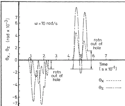
and8~,
in Equation 4.30, describing double point contact motion.Equations 4.30 and 4.35 - 4.37 have been evaluated for a typical system, Table 4~2, the results being shown in Fig. 4.23. It is apparent from considering the rotation about the vertical Z axis occurring at each single contact point, that the peg exhibits a tendency to "walk" out of the hole. In other words the final position efZ when double point contact is re-established, is such that a net rotation out of the hole has occurred during the single point contact phase.
SYSTEM PARAMETERS
SINGLE POINT DOUBLE POINT INTERMITTENT CONTACT
m .766 Kg
2 g 9806.6 mm/s
K 107 mN-mm
X
K 107 mN-mm y
K 107 mN=mm z
Ky I 10 7 mN-mm
h 25 mm
r 25 mm
1237 2
I = Kg-mm
X
I 1217 Kg-mm 2 y
259 2
I Kg-mm
z
Iy, = 1199 Kg-:mm 2
F = 1500 mN
Q 89 rad/s
X
Q = 90 rad/s y
Q
z 196 rad/s
[image:64.597.204.361.194.764.2](Y) I 0 'C""""' X '"'0 0 '-N ()) X ()) {"f) I 0 'C""""' X '"'0 0 1-N ())
7.
6.
4.
2.
r-w
=
10 rod/s
A
~
I'
/1
I \
I \
f\ \ I 1
I I
l
Iy I I I I
rotn
out of
hole
6.
7.
,; \,1
J'l\
)
2.
3.
4.
1 II · \0~--~~~~~~~·~~i~--~·~--~,,~~~~-+~----~---~
\ If\
A
~~~:
I \I
-2.
-4.-6.
r--7.
2.
\If\.
ilt\!'}'L
I ' -1
~l
l \
ri
\! \} \
l
rotn
v
1
'Jr'! '
v
out of
\ I
~'
)
hole
I
I \j
\J
J
8x
8z
/
/\
n~tnot\
(\
f~t~n
\
•
hole
X
v...---...
ole
w
=130 rad/s
~-
4.
6.j
~-
/\10
12. /
w:
o~~~.d--~~--~~i~--~~/.__.'-;---~~~~·----)----~
X
-2.r-())
\ \I
\v\
I' 1/
I
rotn
\
I
into
\)
J\
!
hole
-4
1--6.
-7
LJ'-
L.~.l~~~ ~
rotn
11
out of
'
1I
Ihole
1 1\ I I I
\ I
\ j
8x
[image:65.606.101.536.37.406.2]F
=
mgN
and the friction force F = F
s
then combining the conditions for single point contact, Inequality 4.31, with the simple friction relationship we get
]J > r sina
2h
This inequality must hold for non sliding single point contact. further assume that for a typical system
r = h
then from 4.41 the limiting value of a is
-1
a sin (2].1)
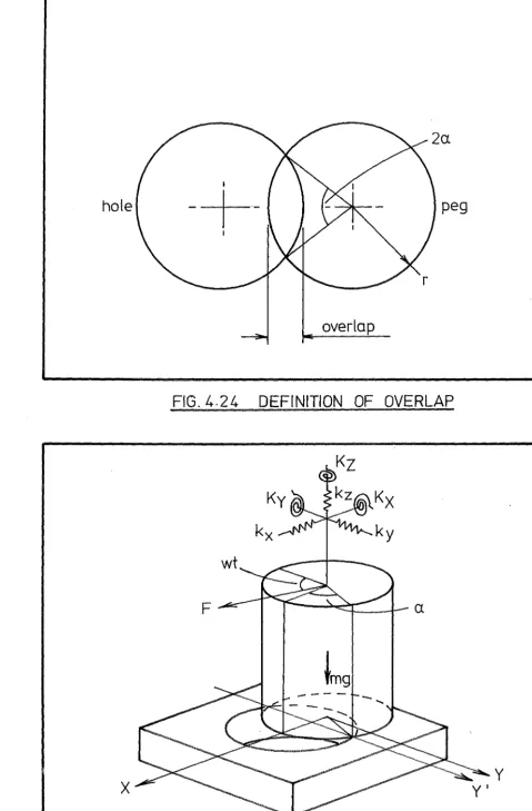
and the overlap as defined in Fig. 4.24 becomes
(4.41)
If we
i.e. for a value ]J
=
.2 the maximum overlap for the walking motion to be possible is only 8.35% of the peg radius. It would seem therefore that walking is not an important mode of behaviour and occurs under the following conditions.(i) In badly misaligned cases, (ii) Where high friction exists.
(iii) The peg height h is large compared with the radius r.
4.8 PEG EDGE - HOLE EDGE HOLE PLANE CONTACT
Initially two point edge-edge contact occurs and the peg is at rest on the hole plane as depicted in Fig. 4.25. The rotating force F is insufficient to cause tipping about the peg edge on the hole plane however tipping occurs about the Y' axis when
2Fhsinwt > mgrcosa (4.42)
When BY' becomes zero again impact occurs and two possibilities exist. If the impact is totally inelastic the system returns to its quiescent state. If elasticity exists, as is possible in the impact of flat surfaces, an impulse is imparted to the peg, and the subsequent free flight motion is determined by the mass and inertia of the peg, and the system constraints. This second possibility is examined in Sec. 4.82.
4.8.1 Equations of Motion for Peg Edge - Hole Edge Contact
The movement of the peg in double point contact, Fig. 4.26, is governed by the equation
+
Mwhere IY' and KY' are as defined in Sec. 4.5 and in this case
M 2Fhsinwt mgrcosa (4. 43)
From the quiescent state therefore t2
f
(2Fhsinwt- mgrcosa)sin~Y' (t2-t)dt t
I
hole
-+-
peg
overlap
FIG. 4.24
DEFINITION OF OVERLAP
F
y
X
[image:68.618.61.540.51.780.2]-2Fh cos~Y,t
2
[ sin(w-~Y,)tIY'~Y'
2(W-~y,)
-mgrcosa
I~ 2
Y'
sin (w+~Y,) t
2(w+~Y,)
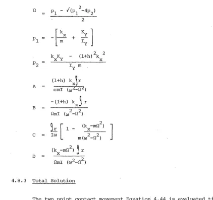
4.8.2 Equations of Motion for Peg Edge - Hole Plane Contact
(4 .44)
The free flight motion of the peg due to the impulse
~
caused by the elastic contact of the peg edge and hole plane is examined. I t is assumed that the impulse~
is applied at the peg edge and that motion occurs only in the XZ plane appearing in Fig. 4.27. The action of the rotating force F is neglected, as the impulse provides a more significant force over the small time period under consideration. The equations of motion .lfoJJ·movement in the X, Z, ey coordinate system are(4.45)
mz
-mg (4. 46)(4. 47)
The solution of Equation 4.46 is
z
(4.46)Equations 4.45 and 4.47 contain static coupling terms and the solutions are of the form
X Asinwt + Bsin~t (4. 47)
eY Csinwt + Dsin~t (4. 48)
where
w
pl + f(pl2-4p2)FIG. 4.26
PEG EDGE-HOLE EDGE DOUBLE POINT CONTACT
[image:70.613.96.537.52.411.2] [image:70.613.94.538.370.774.2]A
B
c
D
k K X y (l+h) 2k 2
X
(l+h) k J r
wmi (MLQ 2 ) - (l+h) kxj r
Qmi (:./ -Q2)
2
k [
l - (kx -mQ ) ]I~ m(w2-Q2)
(kx -mQ2)
~
r Qmi (w2-Q2 )4.8.3 Total Solution
The two point contact movement Equation 4.44 is evaluated t i l l 62
impact occurs. When the peg edge contacts the hole plane, the value of the impulse imparted to the peg edge is obtained from the rotational momentum of the peg in the two point contact mode.
C IY' 8Y' =
r(l+cosct)
where
c
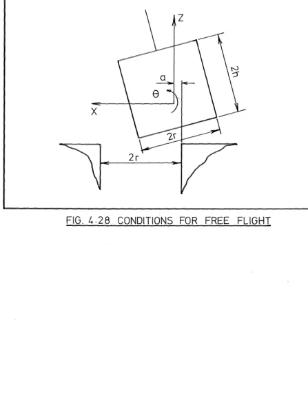
is the coefficient of restitution.For free flight clearly the following conditions must be met. (i) The peg edge may not contact the hole edge, referring to Fig. 4.28 this condition may be written as
zcos8 - asin8 + Xsin8 > rsin8 -