ON COMMUNICATION CIRCUITS
A thesis presented for the degree of
Doctor of Philosophy in Electrical Engineering in the University of Canterbury,
Christchurch, New Zealand.
by
M. W. KELLY B.E. (Hons)
ENCjN~Ht1NG
. LIBRARY
ABSTRACT
Echoes present on telephone circuits are a significant problem on long circuits where the round trip delay is greater than 100 mS. This is particularly so on satellite circuits where
round trip delay is in the order of 500 mS each satellite hop.
An echo canceller has been designed for
New Zealand conditions which is less complex and, therefore, should be less expensive to produce than current overseas models. Although particularly
applicab to New Zealand conditions, the techniques used have wider application. The general problems of echo canceller design are considered with some specific proposals being made.
The two cancellers described here are non-adaptive and are based on a digital transversal ter. The later canceller employs Random Access Memory (RAM), uses pseudo random noise for system identification and compands the speech samples and filter coefficients in a true logarithmic format using multiplexing. techniques for bulky and costly components.
ACKNOWLEDGEMENTS
I am very grateful to my supervisors,
Mr Joseph A. Webb and Mr Rob. Wilkinson, both of whom have provided encouragement,'enthusiasm and have
contributed generously to many stimulating discussions.
I am also grateful to Professor R.H.T. Bates and Dr .J. H. Andreae for their guidance, interest and critical appraisal of my work.
The contribution made by my fellow students,
especially Mr S. J. Lowe is appreciated. The stimulating discussions we had both on my project and related topics were valuable.
The financial and practical assistance of the New Zealand Post Office has been a major contribution to
this project. By financing the project, granting myself paid leave and making toll circuits available for test purposes, their contribution has been a major one and this is appreciated. The typing of the thesis by Mrs Loren Treacy has contributed significantly to its presentation and this is gratefully acknowledged.
iv
TABLE OF CONTENTS
Page
ABSTRACT ii
ACKNOWLEDGEMENTS iii
GLOSSARY ix
PREFACE XI
CHAPTER 1: REVIEW OF ECHO SUPPRESSION AND CANCELLATION 1
1.1 Introduction 1
1.2 Echoes on Telephone Circuits 1
1.2.1 How Echoes Occur
1.2.2 Characteristics of the Echo Path
1.2.3 The Effect of Delay on Speech
Communication
1.3 Echo Control on Communication Circuits
1.3.1 Echo Suppression
1.3.2 Echo Cancellation
1.3.2.1 Non-iterative
1.3.2.2 Analogue Adaptive
1.3.2.3 Digital Adaptive
1.3.3 Area of Research
1.4 Echo Control in an Auditorium
CHAPTER 2: FIRST PROTOTYPE ECHO CANCELLER
2.1 Introduction
2.2 New Techniques
2.2.1 Impulse Response Scaling
2
4
8
11
11
14
17
19
21
26
27
31
31
31
2.2.2 Signal Sample Scaling
2.2.3 Storage of Impulse Response and Signal
Samples
Page
33
34
2.2.4 Accessing and Mul-tiplying Sample Pairs 35
2.3 Conventional Circuitry 39
2.4 Predicted Performance 42
2.4.1 Impulse Response Quan-tisation 42
2.4.2 Signal Sample Scaling 43
2.4.3 Improvements Due to Scaling the Impulse
Response 44
2.4.4 Improvements Due to Scaling Signal Level 47
2.5 Test Results
CHAPTER 3: SYSTEM IDENTIFICATION
3.1 Introduction
3.2 Pseudo Random Binary Noise
3.3 Tri-level Sequence
3.3.1 Limiting Case of Tri-level Sequence
3.3.2 General Case of Tri-level Sequence
49
52
52
52
57
60
61
3.4 Pseudo Random Noise for System Identification 64
3.5 Choice of Interrogation Signal 65
3.6 The Truncated Pseudo Random Noise Sequence 67
3.6.1 Minimising Auto-correlation Error 70
3.7 Quantitative Error Analysis 73
3.7.1
3.7.2
3.7.3
3.7.4
Cross Correlation Error
Noise Error
Colouring of Transmitted Noise Sequence
Total Error
74
75
76
CHAPTER 4: TRUE LOGARITHl'1IC COMPANDING 4.1 Introduction
4.2 4.3 4.4 4.5 4.6 4.7
Speech Characteristics
Impulse Response Characteristics Choice of Logarithm Base
Quantisation Noise
Practical Logarithmic Encoding Logarithmic Quantisation Error
GHAPTER 5: THill VARIANCE OF ECHO PATH 5.1 Introduction
5.2· Causes of Time Variance
5.2.1 Intermi t"tent Time Variance 5.2.2 Cyclic Time Variance
5. 3 Compensa"ting for Phase Roll 5.3.1 Generating Phase Roll 5.3.2 Tracking Phase Roll 5.3.3 Es tima"ting Phase Roll
CHAPTER 6: THE HILBERT TRANSFORM AND ITS APPLICATION TO PHASE ROLL
6.1 Introduction
6.2 The Continuous Hilbert Transform 6.3 The Discrete Hilbert Transform
6.3.1 Sample Period I,imi ta"tion 6.3.2 Finite Length Limitation 6.3.3 Improvements with Windowing
CHAPTER 7: NON-ADAPTIVE, LOGARITHMIC, MULTIPLEXED ECHO CANCELLER
7.1 Introduction
7.2 Multiplexed Circuitry
7.2.1 Analogue to Digital Circuitry 7.2.2 Linear to Logarithmic Conversion 7.2.3 Digital to ~1alogue Conversion 7.3 Calibration Circuitry
7.4 Channel Analogue Circuitry 7.5 Convolution Circuitry
7.6 System Operation 7.7 Interim Test Results
CHAPTER 8: SUMMARY 8.1 Overview
8.2 The Scaled 5 Bit Canceller 8.3 The Logarithmic Canceller 8.4 Hindsight
8.5 The Future
REFERENCES
APPENDIX I
APPENDIX II
APPENDIX III
APPENDIX IV
REPRINTS OF PAPERS
THE CONVOLUTION THEOREM
THE EFFECT OF A SAMPLE AND HOLD CIRCUIT
DETAILS OF ORIGINAL CANCELLER
viii Page
APPENDIX V LOGARITHMIC ECHO CANCELLER DETAILS 246
GLOSSARY
A/D analogue to digital conversion D/A digital to analogue conversion
ERLE echo return loss enhancement defined as the ratio of the echo at the input of transmit path of echo canceller and the residual echo appear-ing at the output of the transmit path
ETA echo transfer attenuation - defined as the ratio of the signal on the receive path (relative to traffic level) causing the echo to the echo on the transmit path (relative to traffic level) PCM
RAM
PROM
PRBS DFT FFT
h(kT)
e (kT)
e' (kT)
r(kT)
n (kT)
pulse code modulation
random access memory - solid state memory in this context
programmable read only memory - solid state memory in this context
pseudo random binary sequence discrete fourier transform fast fourier transform
discrete impulse response of the echo path discrete samples of the -true echo
discrete estimate of the echo
discrete response of the echo path
x
s(kT) discrete samples of the signal leaving the
canceller for the near end subscriber - is used to represent either speech or transmitted noise
Sl (kT) extended version of the transmitted noise sequence
~ , (kT) discrete correlation of the response of the echo
s r
path with the extended noise sequence
W
I (kT) discrete correlation of the extended noise sequences s
with the sequence itself
~ I (kT) discrete correlation of the extended noise sequence
s n
with the noise on the echo path ~ (kT)
sr discrete correlation of the transmitted noise sequence with the response of the echo path to that sequence
~ ss (kT) discrete auto-correlation of the transmitted sequence
a standard deviation of a distribution
dBm level in dB relative to 1 milliwatt in 600n
dBmO level in dB relative to the R.H.S. value of the maximum amplitude signal to be carried without clipping
2W 2 - wire
4W 4 - wire
Tx transmit
PREFACE
Echoes have always been present on national telephone circuits due to the mismatch between local and national circuits. For calls internal to a country, the round trip delay for echoes is normally so short that the echoes are not perceived as §uch. With international calls and especially those via satellite, the delay is such that the echoes are clearly detectable.
Advances in technology, especially over the last decade, have enabled new solutions to be found to this problem which has traditionally been handled with echo suppressors. Echo cancellation refers to the generation of an estimate of the expected echo, which is then used to cancel out the actual echo received. Echo suppressors rely on the introduction of loss into the return path to attenuate the echo.
This thesis is primarily concerned with the
simpler and consequently less expensive model is
presented which while meeting New Zealand requirements could also adapted to similar situations overseas.
This thesis describes two cancellers. The first is an ini
inexpens
attempt to provide a simple and
unit. It is felt that this was a necess and important step in the evolution of the later design. In itself had certain inherent disadvantages but provided a background on which the later model was developed. This later model overcame the now obvious shortcomings of the first canceller and uses techniques not previously applied to the echo cancellation
Other proposals are made which are not included in this design but are applicable to problems experienced outside New Zealand. "The use of" true logarithmic compression of speech and filter coefficients, pseudo random noise
testing of the echo path and the application of the Hilbert Transform are among these. New material and applications are included in Chapters 2-7.
In Chapter 1 an introduction is given to the reasons for echoes on communication circuits and their character-istics. A summary of echo suppressor and echo canceller developments and a critical appraisal of their
In Chapter 2 the first prototype canceller is described and the results of tests are given. The shortcomings are described. This canceller was an introduction to this field of research for the author. Attempts to simplify certain aspects in fact resulted in some undesirable complexities. The use of Random Access Memory proved convenient but the principle of analogue gain adjustment around the digital processing section might have been a source of difficulty in an operational situation. The policy of single impulse testing of the echo path; although attractive for its simplicity, could have proved ineffective without some form of averaging.
In Chapter 3 the primary problem in echo canceller design is studied. Problems with the method for establishing the filter coefficients in the first canceller are explained. The development of a modified version of the widely used psuedo random binary sequence is explained as a suitable method of averaging out the noise contribution to errors in measuring the impulse response. Reasons are given
In Chapter 4 true logarithmic companding is proposed as a suitable format for the storage and processing of speech samples and filter coefficients. The conversion from a 12 bit linear format to an 8 bit logarithmic format not only reduces storage but drastically simplifies the convolution process. The suitable choice of a logarithmic base is explained along with the dynamic range considerations and the problem of taking logarithms near zero.
In Chapter 5 the complications of time variance
riv
of echo path characteristics are discussed. A new method of tracking cyclic time variance is proposed which uses the predictability of this form of time
variance to advantage. This problem severely restricts the performance of the normal adaptive canceller where i t occurs. The problem had not previously been attacked in this manner.
In Chapter 7 the design of the echo canceller based on the previously developed principles is discussed. A multiplexed system is shown which is very cost effective on a per channel basis, with
most expensive components including coefficient measuring circuitry being time shared over many circuits. Results of interim tests on this coefficient measuring circuitry are given but cancellation tests are not completed.
In Chapter 8 a summary of the project is given in light of the prescribed aims. A section headed
'Hindsight' lists some of the errors of jUdgement and misdirected effort which are more easily recognised afterwards. The future of the project is considered as i t becomes the responsibility of the Post Office.
Papers completed to date on topics related to this thesis are as follows:
Webb, Joseph A. and Kelly, H. W., "Telephone Echo Cancellation for Satellite Terminals" IEEE Conf. Proc., ICC ' 78, Vol. 1, pp. 10.5.1 -10.5.5.
Webb, Joseph A. and Kelly, M. W. "Delay Lines help generate Quadrature Voice for SSB" Electronics, April 1978, pp. 115 - 117.
Webb, Joseph A. and Kelly, M. W. "Practical
Sampling Considerations" 1979, paper resubmitted to IEEE Trans. Comrnun. following request for further information.
xvi
CHAPTER ONE
REVIEW OF ECHO SUPPRESSION AND CANCELLATION
1.1 INTRODUCTION
The presence of echoes on telephone circuits causes difficulty in communication where the round trip delay of the echo is long. This is the case with international circuits, ially where satellite circuits are
encountered. The traditional method of reducing the level of echoes on telephone circuits has been to use echo suppressors. Suppressors have not been entirely satisfactory, especially where satellite circuits are involved, and the delay is excessive.
With advances in modern technology, echo cancellation as a means of reducing echo levels has received a lot of attention. The causes of echoes, and the development of both suppressors and cancellers to control the problem, are explained in this chapter.
A mention is also made of the application of the signal processing techniques used in echo canceller design to the processing of echoes inan auditorium.
1.2 ECHOES ON TELEPHONE CIRCUITS
2
(i) The local circuit connecting the subscriber to his local telephone exchange, which comprises one bi-directional circuit, normally of one pair of
wires. This circuit is termed a 2-wire (2W) circuit. (ii) The national circuit, which connects exchanges
throughout the country on various types of
transmission systems, comprises two uni-directional circuits and is often called a 4-wire (4W) circuit with separate send and receive paths.
1.2.1 How Echoes Occur
It is at the junction of the local and national
circuits that echoes are assumed to be generated. Although this is not strictly true, as echoes can originate at any mismatch in the 2W circuit, i t is a convenient and safe assumption. At this junction is the Hybrid Transformer
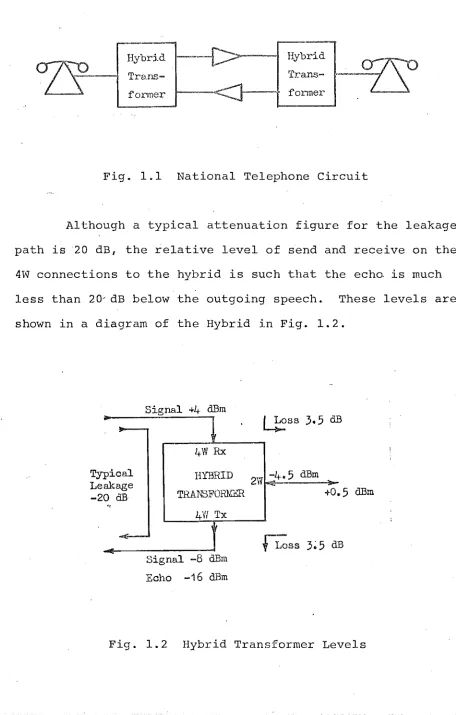
2-wire to 4-wire interface circuit, which ideally passes all incoming speech from the national circuit out to the local circuit without passing any of this energy back on to the outgoing side of the national circuit. However, these units are never perfect and are seldom adequate. As these transformers are permanently associated with the national circuit, any local circuit may be connected to them, all of which will present a different load to the 2W connection on the Hybrid. A diagram showing a national telephone
circuit can be seen in Fig. 1.1. ~ith a varying load on the Hybrid Transformer i t cannot be satisfactorily adjusted
are of lower amplitude, with the hybrid leakage, therefore, normally being the major contributor.
Hybrid
--[>---
HybridTrans-
Trans-former former
Fig. 1.1 National Telephone Circuit
Although a typical attenuation figure for the leakage path is 20 dB, the relative level of send and receive on the 4W connections to the hybrid is such that the echo is much less than 20~dB below the outgoing speech. These levels are shown in a diagram of the Hybrid in Fig. 1.2.
...
Typ ical
Le -2
akage OdB
,<
Signal +4 dBm
4W
RxHYBRID
TRANSFORJl:ER
4Vl
Tx
Signal -8 dBm
Echo -16 dBm
L!!>ss
3.5
dB2W
:4.5
dBro+0 ,,5 dBm
fLoss
3;5
[image:19.552.47.503.118.834.2]4
It is, therefore, apparent that to some extentechoes will be present on all calls on the national network due to the imperfect nature of the match between local and national circuits.
1.2.2 Characteristics of the Echo Path
Many tests have been carried out on national
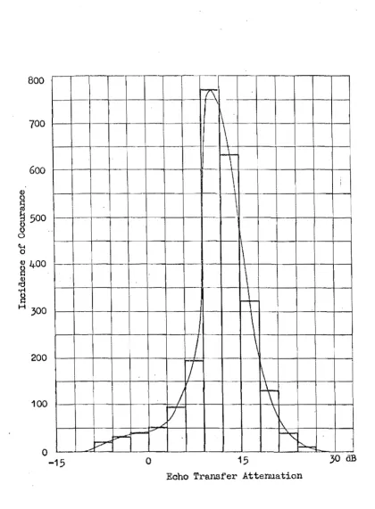
telephone networks to establish the characteristics of the echoes encountered by subscribers. Results of tests on the French network and the American network have been published by CCITT(12) and Duffy(37) respectively. These results give a good basis for establishing echo characteristics. Levels of echo are given by the Echo Transfer Attenuation (E.T.A.), being defined as the relative level of the echo on the send path, to the signal producing the echo on the receive path, where both paths are at the same nominal traffic level. This figure, therefore, takes account of the different levels for each path at the hybrid and gives a true
indication of the level of the echo relative to the speech generating it. Results from tests on the French network, published by
CCITT(12~
give a mean E.T.A. of 13.6 dB with a standard deviation of 5.1 dB. A histogram showingdistribution of E.T.A.s is reproduced from the CCITT report in Fig. 1.3.
800
700
600
~
~ 500
8
o \H o8
400 ~ 'rl8
H 300
200 100
r--o
-15+
I~
i---
~J;;~-o
.. '-r7\
\~
, ! i \\
\\
\
+
\
I
\
II
T
i\
/
rt
iI
)T
\
1\
~
h
15 30 dB
Eoho Transfer Attenuation
[image:21.554.41.462.56.628.2]6
not perceived as an echo and appears as sidetone to the subscriber.
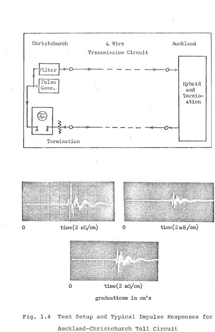
The other characteristic of interest in echo canceller design is the pattern of the impulse response of the echo path and its energy distribution. The above tests established that the maximum length of the impulse response to the end of the active period was 32 mS. This may not be true of larger countries but is true of the New Zealand network. The impulse response comprises a delay portion where no activity is present, and then an active period where 99% of all energy is found in a period of 8 mS. To verify that these characteristics were also typical of the New Zealand network some impulse response measurements were made between Christchurch and Auckland, a distance of approximately 550 miles. An initial delay period of 11 mS, with an active period of 8 mS, was typical. As the distance between Christchurch and Auckland is two thirds of the maximum circuit length in New Zealand, a 32 mS impulse response would not be exceeded on the New Zealand network. A group of /typical impulse responses obtained are shown in Fig. 1.4, I'long with the test circuit used.
o
Christchurch
A
Termination
4 Wire
'fransmission Circuit
til1le(2 ruS/cm)
o
o
time(2 mS/om)graduations in em's
Auckland
l(ybrid antI
Terrdn-ation
time ( 2mS/em)
[image:23.552.44.486.80.760.2]8
explanation this phenomena is given in Chapter 5. Results of tests on the Australian network(28) have
shown 6.6% of all subscribers will encounter a circuit with phase roll on an international call, with a further 8.2% possibly encountering one. Of these subscribers, 30% will encounter phase roll greater than 0.5 Hz, with a maximum rate of phase roll at 5 Hz.
1.2.3 The Effect of Delay on Speech Communication.
There are two distinct effects of delay on communication between two subscribers on a telephone
circuit. first is the effect of having to wait longer than normal for a reply. This effect causes no di
until delay exceeds 50 milliseconds. The second is the effect that this delay has on echoes, which would otherwise provide no difficulty. The combination of these e
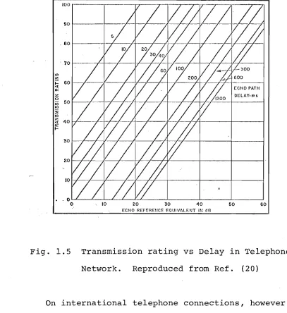
causes confusion and considerable difficulty as the delay es. Subjective tests have been carried out by
CCITT(20) to ascertain the relationship between echo level, round trip delay and difficulty experienced. A graph
showing these relationships is given in Fig. 1.5, having been reproduced from this report.
t'>
:z
~
It: :z o CIl
~l
::0::
CIl z
0:(
It:
I-ECHO REFERENCE EOUIVALENT IN dB
Fig. 1.5 Transmission rating vs Delay in Telephone Network. Reproduced from Ref. (20)
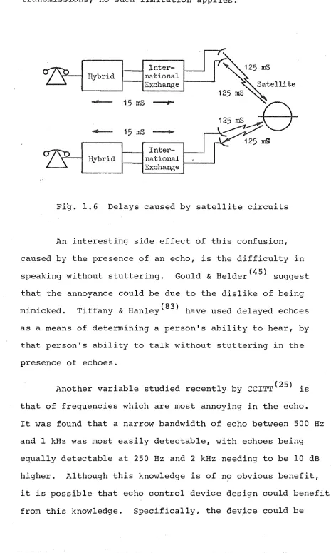
On international telephone connections, however, the problem affects all countries. This is especially so where international connections are made via satellite. The physical length of the round trip path in this case becomes much greater than is the case for cable circuits. This results in a significantly increased delay for echoes. An illustration of the path lengths and subsequent delays
[image:25.552.53.460.63.507.2]transmissions, no such limitation applies.
Inter-Hybrid national
Exchange
1----""
Hybrid
Inter-national
r-~ ~--~
3xchange
125 mS
Fig. 1.6 Delays caused by satellite circuits
An interesting side effect of this confusion, caused by the presence of an echo, is the difficulty in speaking without stuttering. Gould & He1der(45) suggest that the annoyance could be due to the dislike of being mimicked. Tiffany & Hanley(83) have used delayed echoes as a means of determining a person's ability to hear, by that person's ability to talk without stuttering in the presence of echoes.
Another variable studied recently by CCITT(25) is that of frequenc s which are most annoying in the echo.
10
[image:26.552.37.502.58.834.2]designed so as to more accurately suppress these frequencies at the expense of others.
Although echoes are a major contributor to
conversational difficulties, the confusion caused by the delay alone is significant. This problem has been widely studied and the effects published. Richards(75) has been a major contributor in this area.
1.3 ECHO CONTROL ON COMMUNICATION CIRCUITS
There are two main methods of reducing echo levels on telephone circuits:
(1) Echo Suppression (2) Echo Cancellation
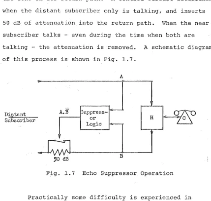
Echo suppression refers to the practice of inserting a fixed amount of attenuation - normally 50 dB - into the return path, to prevent the echo being retransmitted to the distant subscriber. Echo cancellation involves no such interruption to the path but relies on the generation of a second echo by a filter, which is then used to cancel out the genuine echo. Ideally the filter represents an accurate model of the true echo path, and the cancellation by
subtraction is perfect.
1.3.1 Echo Suppression
the echo on return path. A control circuit determines when the distant subscriber only is talking, and inserts
50 dB of attenuation into ,the return path. When the near subscriber talks - even during the time vlhen both are
talking - the at,tenuation is removed. A schematic diagram of this process is shown in Fig. 1.7.
D~tant Subscriber
A.
uppress-....----1 or
Logic
,0 dB
A
B
H
Fig. 1.7 Echo Suppressor Operation
Practically some difficulty is experienced in determining whether speech present at I B I is due to I C I
or an echo from IA'. If the decision was made as shown in the simple diagram above, an echo present due to IAI would appear as speech from I CI and the suppressor would
never operate. A decision must, therefore, be made as to
12
the origin of the energy. The ever present conflict of cost versus performance means that wrong decisions are invariably made at times by the circuitry. These mistakes increase
[image:28.552.55.484.55.462.2]which signals are echoes has been studied widely by many people including unrue(85}.
Specifications quoted by S.T.C. for their echo suppressor models SP-lO and SP-20 give an example of the characteristics of modern suppressors. These suppressors insert a 60 dB loss in the transmit path when incoming speech only is present. When both transmit and receive paths are in use, the 'break-in' circuit inhibiting
suppressor operation comes in when the transmit signal level is higher than the receive level. During this time a 6 dB pad is inserted in the receive path. This same inhibited operation occurs when speech is only present on the transmit path. Those performance specifications of particular
interest are:
Operate times:
Hangover times:
Suppression: <5 mS
Break-in: <30 mS (receive level constant) - typically 20 mS
Suppression: 40-75 mS (typically 50-60 mS) Break-in: 150-350 mS
(typically 200-300 mS)
Suppression sensitivity: -31 dBmO
+/-
0.3 dB at 1000 Hz Break-in sensitivity: -31 dBmO+/-
2 dB at 1000 HzEcho suppressors at present represent the most widely used means of reducing echo levels, due mainly to their
14
technology of the time.
1.3.2 Echo Cancellation
with the problems experienced by echo sors-on
long delay circuits, and with advances in technology
appropriate to real-time signal processing, echo
cane lation has received much attention recently. The
basic principle is to model the echo path in the form of a
Iter, to generate a replica of the expected echo, which
is then used to cancel the echo that is received. A diagram
illustrating this principle is shown in Fig. 1.8.
lI'{W)
EchoPath
Hew)
Fig. 1.8 Echo Canceller Operation
The diagram in Fig. 1.8 is, of course, a gross
over-simplification of the process involved but illustrates
the principle. The automatic modelling of the transfer
function H(w) by H' (w) is a complex and expensive process,
and the means of obtaining the echo path characteristics
are varied. Once the circuit characteristics are
realisation are similar in all cancellers.
The realisation of the filter is based on the convolution theorem. The proof of this theorem is given in Appendix II. The theorem states that the product of two functions in the frequency domain, has an equivalent operation in the time domain described by the convolution integral. In the canceller the product of the frequency domain representations of the speech and filter character-istics S(w) and HI (w) respectively, is replaced by the convolution of the time domain representations of the two functions.
E' (w)
=
S(w) x HI (w)becomes e I (t)
=
S (t)*
hi (t) --- convolution theorem00
or e l (t)
=
~
hi (T)s(t-T)dT --- convolution integral-.co
For signal processing this continuous case reduces to the discrete approximation, where samples of s(t) and hi (t) only are known, and they obey the sampling theorem. The equation for the discrete case becomes:
00
e l (kT)
=
l:h' (iT)s{(k-i)T} for k and i integer- 0 0
T is sample period
The practical realisation of this equation limits the impulse response of the echo path hi (kT) to 0 ~ k ~ L , and e l (kT) is only calculated for one value of k, normally
time reference. It is convenient to consider k
o
to the time the most recent sample of the speech waveform was taken. As only in an infinite bandwidth system will hI ( have any value at i=
0, the summation is further restr to 1 ~ i<
L.The discrete convolution equation reali by filter then becomes
e'(lT)
=
L
L
hl(iT)s{(l-i)T} i=lThis, therefore, generates the estimate of the value
echo waveform at time IT after the last speech sample was taken. The equation requires speech samples s(kT)
time period 0 ~ k ~ (l-L) which must be held in memory, as must the L samples of hI (kT).
16
As was established earlier, the length of the impulse response required is 32 mS including the delay prior to the active period. With the maximum frequency less than 4 kHz, a sampling rate of 8 kHz is satisfactory and is an acc
standard in time division multiplexed systems. The sample period is, therefore, 125 flS, meaning tha·t 256 samples are required to make up the discrete impulse response h' (kT). In the final form the discrete convolution equation becomes:
256
e'(lT)
=
L
hI (iT)s{(l-i)T} i=lactivity. By knowing that only 8 mS or 64 samples of hi (kT) need be non zero, the length of the convolution equation can be reduced with an appropriate delay
introduced. However, at this point the impulse response will be considered to be 256 samples long.
The echo canceller can be realised either digitally or with analogue circuitry. with the advances in digital signal processing technology, especially in the area of memory, the trend is towards digital implementation.
Another of the variables in canceller design is the method of obtaining the impulse response samples as filter
coefficients. The main thrust of research in this field has been towards a digital adaptive canceller which
continually adapts its filter coefficients to minimise the echo. This enables variations in echo path characteristics to be followed, with the system converging to a satisfactory level of cancellation in the order of 1 sec. This method has its own set of problems as do other methods. Each alternative type of canceller will be dealt with
individually to ascertain its relative advantages and disadvantages.
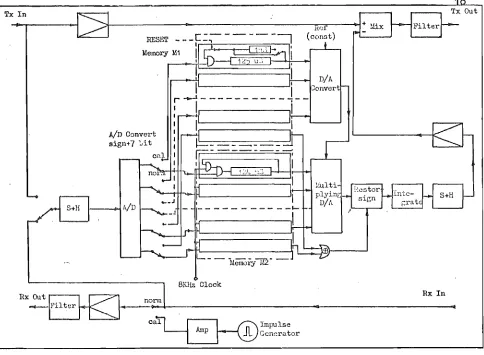
1.3.2.1 Non-Iterative Echo Canceller
Tx In
RESET
AID C:mvert
sign+7 '-'it
8KHz Clock
Rx In
Rx Ollt ~.~ norm
~~~~~~~-~~---~~---q
call
r-::::I
{;;\
Impulse~Gcnc~ator
Fig. 1.9 A Blockless Echo Suppressor. Reproduced from Ref. (63)
To measure the impulse response of the circuit an impulse is transmitted around the echo path, and the response of the echo path measured directly. The resultant filter
coefficients are stored in digital delay lines. The speech samples are also stored in digital delay. lines with both sets of samples being recirculated around the delay lines to permit access to them. Once entered the filter
[image:34.552.29.513.48.403.2]are achieved with multiplying Digital to Analogue (D/A)
convertors. The output from the D/A convertor on the output of the stored coefficients provides the reference for the convertor on the speech samples. Results of tests
illustrated that with 8 bit quantisation of coefficients and speech samples, a cancellation of 20 dB could be achieved. This reduction in echo level is termed Echo Return Loss Enhancement (ERLE).
The main disadvantage of such a system is that the presence of any noise or subscriber's speech at the time of impulse response measurement will cause errors in the filter coefficients. This 8 bit linear quantisation also means quantisation noise error will be only 48 dB below the maximum level expected - or approximately 28 dB below the R.M.S. value of active speech. Dalhgaard & Nielson(33) found the R.M.S. value of active speech to be 17 dB below the R.M.S. value of the maximum level accommodated, or
o
dBmO. This noise will be present even in the absence of speech. A further complication is the necessity to check for unsatisfactory cancellation due to random and sometimes continuous changes of echo path characteristics.1.3.2.2 Analogue Adaptive Echo Cancellers
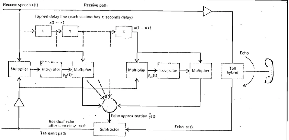
The analogue adaptive canceller requires a vast amount of analogue circuitry to achieve the processing required. The products of the convolution equation are formed by analogue multiplication with a multiplier required for each coefficient. Furthermore, another
is obtained by correlating the cancelled echo with the speech samples. A simple explanatory diagram reproduced from Gould & Helder's paper(45) is shown in Fig. 1.10.
20
The complexity of the operation, using analogue multipliers, becomes clear on studying this diagram.
Rec£'lve 5pc('ch x(l) F/cceive Pill"
----~---~~~>---~
Echo
: Totl : \
: hybnd ;
L . __ j~
Fig. 1.10 Analogue Adaptive Echo Canceller. Reproduced from Ref. (45)
[image:36.553.22.524.202.446.2]this correlation. There are various algorithms for such a corrective process. This then represents the principle not only of analogue but also of digital adaptive
cancellers. The main disadvantage with analogue
realisations is the necessity to have multipliers for each coefficient resulting in duplicated circuitry. For this reason and others, analogue cancellers have £ound little favour with researchers in this field.
Experiments by Brueggemann and others(5,6) working at the Australian Post Office Laboratories have also been based on the analogue adaptive canceller. A variation in the form of an initial transmission of a pseudo random noise
I
sequence for the filter to converge on is used, resulting in an initial convergence in 160 mS. Cancellation of around 20 dB was achieved.
1.3.2.3 Digital Adaptive Echo Cancellers
The most comprehensive research, development and operational testing of echo cancellers has been undertaken by COMSAT under the sponsorship of INTELSAT. This commenced with an initial paper by Kato and others(9l) describing a prototype canceller. This first prototype incorporated an initial calibration where a single pulse was transmitted and the response sampled as in the case of the non-adaptive canceller described earlier. From that time on, the
22
considered inadequate. The convergence time of the adaptive structure was around 1 sec, and this was unsatisfactory for following anything but slow rates of phase roll.
Improvements on this basic canceller design in terms of the convergence algorithm were reported by Campanella and others(30). The initial calibration pulse was abandoned and i t became a completely adaptive canceller.' The
convergence time reduced to about 500 mS, and an echo return loss enhancement of 21 dB was achieved when converging on noise. For convergence on speech, a reduction of about 3 dB in ERLE was suffered. More detailed tests were carried out on the effects of phase roll, and i t was found that the reduction in ERLE .was be·tween 2.4 dB/rad/sec and 6 dB/rad/
sec as the noise being used as a test signal vari~d from -10 dBmO to -30 dBmO respectively. A block diagram of this canceller is shown in Fig. 1.11.
HYBRI
PROCESSOR
BLOCKING AMPLIFIER
CONTROL __ LOOP
I I I I
I
I
I
L _ _
vlt) r ( I ) _
LEGEND:
Kit) - incoming ';9",,1 V It) - .ignal return"" from echo path
V It) - appfOximated
echo lignal
f (t) - error Sigrull AID - analog·to-digital converter
D/A - digital·to·analQ9 converter
----,- xlt)
The first results of field trials on this canceller were published by CCITT(24) on initial tests between the United States and the United Kingdom. The echo canceller performance was understandably compared with that of the echo suppressor. In about 80% of the cases, cancellers showed an improvement over the suppressor and in the other 20% no significant difference was noted.
More detailed technical results were reported 'by Suyderhoud and others(8l) in 1975, following world wide
field trials. Convergence time of 3 words of a conversation and echo return loss enhancement figures in the order of 25 dB were achieved. No cases of phase roll were noted and therefore no conclusions were drawn on the ability of the cancellers to follow it. It was accepted that the canceller would not work satisfactorily for phase roll rates greater than 0.5 Hz. The sUbjective assessments
showed that cancellers significantly improve the quality of the call where echo is the primary problem. An important conclusion at this stage made by the authors was that the designs exceeded the limits of economic viability. Results of these same tests were also reported by CCITT(26) .
The effect of noise on the operation of adaptive cancellers was studied by Rosenberger and Thomas (76) .
The aim of this was to determine the effect of double talk on the performance of the adaptive section. It should be realised that these tests were limited to circuits which were time invariant. It was found that during convergence on speech i t converged on a frequency selective basis, the fit being best in that portion of the spectrum where most energy was concentrated. Conversely, double talk caused a divergence also on a frequency selective basis. For this reason i t is normal not to permit the filter coefficients to adjust during double talk. Any time variance must
therefore be adjusted to following the period of double talk, therefore limiting its ability to handle phase roll.
Gitlin and Weinstien(43) working at Bell Labs. also studied the effect of interference on the tracking ability of digital adaptive cancellers. Although
restrictions needed to be placed on the step size of any adjustment, they showed that convergence was possible in the presence of double talk. This was desirable and in fact necessary in the case of long periods of double talk as encountered in the case of data transmission.
Gitlin and Thompson(42) proposed a phase adaptive structure at a time when this author had developed just such an approach. The intentions are witnessed by an
article by Webb and Kelly(87) on the use of a tapped delay line to generate a quadrature component of voice. By
proportions any phase shift can be generated. The phase tracking can therefore be handled as a separate problem without varying the filter coefficients. Further details on this approach are given in chapters 5 and 6 as a
contribution by this author. Gitlin and Thompson (42) , however, persist with the normal adaptive structure as well as the phase adaptive structure.
A 12 channel digital adaptive canceller was
designed at Bell Labs. by Duttweiller(39). The time sharing or multiplexing of components was shown to make the
otherwise conventional adaptive canceller more economically attractive.
Working at the Research Department, Telecom Australia, Demytko and English(35) have studied the effect of time variance and, specifically, phase roll on the performance of echo cancellers. They show that a high speed adaptive canceller can satisfactorily handle phase roll up to 2 Hz. High speed adaptive cancellers are, however, susceptible to noise or near end speech and are not widely used. This of course is an example of the common compromise in control systems of a fast response being traded for noise immunity. The attention paid to phase roll in Australia is due to the relatively high probability of encountering this effect on the Australian telephone network.
This is similar to the true logarithmic coding proposed in this thesis, and results in simplified generation of products in the convolution process. The use of the A-law companding code, as used by Horna, introduces errors when it is assumed in the processing that these are in fact true logarithms. It will be shown in chapter 4 that true logarithmic coding can be achieved despite the problem of taking logarithms of numbers near zero.
The main distinguishing feature of the cancellers described in this thesis is their non-adaptive nature and resulting simplicity and cost advantage, without any compromise on performance.
1.3.3 Area of Research
The major factor inhibiting the widescale
introduction of echo cancellers is the high per channel cost compared with suppressors. The main reason for the continued interest in the adaptive structure appears to be its ability to follow time variances. As they are in fact unable to follow satisfactorily phase roll of greater than about 1 Hz i t seems a nevi approach is justified.
It was therefore decided to adopt a direct
measurement approach in finding the filter coefficients. As phase roll can be ignored on New Zealand circuits, an economical unit should be able to be designed. To give the canceller wider application, the problem of phase roll is treated separately. Any intermittent.time variance is accommodated by a complete re-calibration.
For a canceller to be a viable alternative to the suppressor i t should have advantages proportionate to its extra cost. Existing cancellers do not meet this
requirement.
1.4 ECHO CONTROL IN AN AUDITORIUM
Although not directly related to communications ciircuits, the processing of the sound signal using similar techniques to those used in echo cancellers, could
artificially enhance the acoustic properties of an auditorium. There are two aspects which the author
considers as possible applications for these techniques. The first is the more directly related one of reducing
echoes to prevent feedback causing instability. The second is to model the characteristics of an ideal auditorium as a transversal filter. To establish the feasibility of such a proposal, some measurements were made of the impulse
response of the Ngaio Marsh theatre at the University of Canterbury. A photograph of the response of the auditorium at the microphone, to the transmission of an impulse is shown in Fig. 1.12, along with the test setup used for this measurement.
As the length of the response is about 500 mS for 90% of the energy, about 4000 samples of the impulse response would need to be used in the transversal filter to achieve a 10 dB reduction in the feedback at the
28
Pulse Lmplifier
-=<
GeneratorSpeaker
-Audi torium
Eltereo L ~..-
e-O
Tape
Recorder H .Amplifier
"
-I 11l~cropLone r • ,
o
time (100 IDS/om)
4000 sample pairs must be multipled every 125 ~S using the same principles as discussed for echo cancellation in the previous section. As this impulse response of the auditorium was measured for an empty auditorium, i t is expected that i t would be shorter for a full auditorium. The worst case, however, must be catered for.
The other aspect of echo control has potentially
.
more to offer and in itself would also overcome the
problem of instability due to feedback. By modelling the trans function of an ideal auditorium as a transversal filter, the sound can be transmitted as though i t had already been subjected to it. If i t is transmitted into a dead auditorium, with no echoes, then i t should sound as i t would in that ideal auditorium. As the cost of
physically constructing such auditoriums increases, the attractiveness of such a proposal becomes obvious. The application of this to outside theatres would also enhance the sound in an otherwise difficult environment.
If a 0-15 kHz bandwidth is required, a 30 kHz minimum sampling rate would be needed. This is based on a high quality audio system for such applications as orchestral concerts. For an impulse response length of
the ideal transversal filter remains unchanged, which
simpli s the circuitry. It is also possible that
paral processing would make this technically
feasible now.
No further work has been carried out by the
author on this proposal to date.
CHAPTER TWO
FIRST PROTOTYPE ECHO CANCELLER
2.1 INTRODUCTION
The main feature of this canceller was in its use of Random Access Memories (RAMs) for storage of impulse res-ponse and signal samples. This enables the samples to be accessed simply and efficiently reducing the speed required for processing. An experimental technique of scaling the impulse response and signal sanples provided for a reduction to 5 bit digital representation enabling simple digital
mUltiplication. Multiplication was achieved by using a Progranunable Read Only 1',1emory (PROM) as a multiplication look-up table with the two 4 bit magnitudes providing the address and the output being the product of the two.
2.2 NEW TECHNIQUES
2.2.1 Impulse Response Scaling
As the echo level can vary up to 20 dB due to variations in the mismatch at the hybrid, then obviously the peak value of the response will vary by a similar
32
amount. If, for example, 8 bit quantisation is used, the gain prior to A/D conversion 1S adjusted so as the maximum
peak expected will represent a full scale input to the converter and will be quantised to
+/-
128 levels. This limits the possible echo reduction to 20 log 128 = 42 dB. However, an impulse response having a peak of only 1/10 ·the maximum peak expected will be quantised to only+/-
12 levels. The result is a possible echo reduction of only 20 log 12=
22 dB. By adjusting the gain around the filter the peak of each impulse response represents full scale input to the A/D converter and hence equal quantisation and similar echo reduction is achieved.In this echo canceller only 5 bit representation was used with the gain being adjusted so that the impulse res-ponse was quantised to
+/-
15 levels. This was achieved by transmitting two pulses for calibration purposes. The first was used to determine the unscaled peak amplitude which was stored and used to control the gain so that the peak ampli-tude of the response to the second pulse would be quantised to the full+/-
15 levels. This gain control prior tovoltage also determined the gain of a multiplying D/A converter which compensated for this gain adjustment after ltering.
'2.2.2 gnal Sample Scaling
A similar arrangement provided for the scaling of the signal samples, although this was expected to be less satisfactory. The scaling factor was derived from a peak detector charging circuit and the gain adjusted by using
this detector output to control the divider circuit. The "gain around the fi Iter was not permitted to vary by more than ~ the least significant bit over any 32 mS period. This ensured that signal samples quanti sed subject to this gain control were processed with the correct gain compensation at the output for the duration of their 32 mS storage period in the canceller. This
requirement was not difficult to obtain for the decaying control voltage but difficulty arose with the occurrence of a new signal peak. The peak detector output at any
time represented the current full scale input of the A/D converter. For a new and larger peak to be quantised the gain was immediately altered so that the new peak was represented by the full scale input to the converter. This meant that all samples stored in the previous 32 mS were processed with the wrong compensatory scaling at the output. This would cause a burst of echo of 32 mS duration. The severity of this would have needed to be rmined
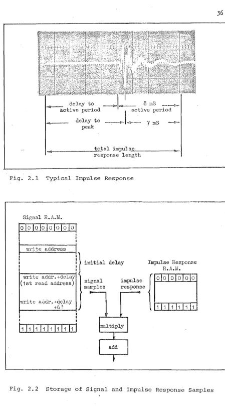
2.2.3 Storage of Impulse Response and Signal Samples
Perhaps the greatest advantage of this echo
canceller was in its incorporation of high density solid .state memory. In using RAMs for storing the signal and
impulse response samples, a more convenient method of accessing samples was available. This compares favour-ably with existing methods of rotating samples around a shift reg'ister to enable access to them as they appear at the output. With RAHs i t was merely a case of counting thr?ugh the consecutive memory addresses.
This permitted another major improvement over existing methods. Although a total period of 32 mS was considered in the convolution i t was known that only 8 roS of that period had non zero impulse response samples. This meant that only 64 samples of impulse response need be
stored and only 64 of the 256 signal samples need be
accessed for multiplication each sample period. By deter-mining the delay to the active period of the impulse
samples) period. By using RAMs all previous 32 mS of signal samples are stored but only the 64 corresponding to the
active period need be read each sample period. This negated the requirement for separate signal delay or the extra speed required to convolve 256 sample pairs. A pictorial representation of the storage of samples in RAM
can be seen in Fig. 2.2.
2.2.4 Accessing and Multiplying Sample Pairs
The 64 impulse response samples were stored in RAM in ~inary address positions 000000 to 111111, with the
first sample of the active period (- 1 mS on delay to peak) appearing in address 000000. The position of these impulse response samples in memory remained unchanged. To access these samples for multiplication i t was necessary to count through the memory address 000000 to 111111.
The storage of signal samples is slightly more
complex. The first signal sample could be stored anywhere but each subsequent sample was stored at the binary address preceding that of the previous sample. A new sample was stored every 125 uS corresponding to an 8 KHz sampling rate. As signal samples were stored for 32 mS, 256 bytes of storage were required representing an 8 bit (0 to 255) address. If the previous sample was stored at address 00000000 the next address for storage would be 11111111. The write address could then be provided by a decrementing
delay to ~..r 8 mS { 1 : -aoti ve period I_ active period
~'--_ _ delay to ~v "':.:.~-
7
mS-'It,,-peak
~ _ _ _ _ _ ~t::::...otal impu].8~e,--_ _ _ _ _
'!!I-response length
Fig. 2.1 Typical Impulse Response
Signal R.A.M.
write adcr.+delay (1st read address)
Iwrit
~
aGdr.; deloy +6)•
•
I t
I ,
initial delay
signal sarnples
impu.lse response
-~ltiply
t
add
+
Impulse Response
R.A.M'.
[image:52.555.50.500.16.834.2]The address from which the 64 samples must be 'read' for multiplication were determined from the delay prior to the active period of the impulse response. If the delay to the peak was 1 mS then the delay to the first impulse
response sample would be zero and the address of the first signal sample to be read would be the current write address. The next 63 samples were those in the next highest 63
addresses. These are the last 64 signal samples stored. If the delay to the impulse response peak was 5 mS, the delay to the active period is 4 mS, and the first read address would be the current write address plus 32
representing a delay of 4 mS or 32 samples. A pictorial representation of this is found in Fig. 2.2.
with the read addresses for the impulse response and signal samples being incremented concurrently the sample pairs were used as an address for a PROM which had as its output the product of the 4 bit. magnitudes. As the samples are stored in a sign and magnitude format the pro-duct of magnitudes is provided by the PROH. The 5 th bits
sign bits
°1
signal Signal
sample R.A.M.
°1
address
Os
Multiply product
A,., P.R.O.M.
i_'5e { ,
°1
response Impulse
sample Response
address R.A.M.
Os
AO
Fig. 2.3 Generation of Products
The first read address is derived from the discrete convolution equation:
N-I
y{kT)
~l:h{iT)
.x{{k-i)T)i=O
As i t takes one sample period to calculate the expected value of the echo at a given time, i t is convenient to calculate i t for a time of one sample period (IT) after the latest signal sample is taken.
Now the total impulse response and set of signal samples cover 256 sample periods so:
k is required to be I as we are to calculate the value for I sample period T after the time of sampling defined to be t
=
0 for convenience.If h(t) is the impulse response and is zero for all It' less than aT and for all 'tl greater than bT then we only need consider h (t) over the period aT ( iT ~ bT. As we have determined (b - a)T
=
8 mS then b - a=
63 and b = a+
63. The surrunation therefore becomes:63+a
y(T) =l:h(iT) .x(l - i)T a
where 'a' is the delay in sample periods to the t impulse response sample. The first read address
speech samples is (a
+
1) greater than the current write address as x{(l - i)}T goes from x{(l - a)T} through tox {(
I - 63 - a) T}.2.3 CONVENTIONAL CIRCUITRY
Apart from the specifically mentioned atures of the circuit, i t was conventional as far as echo cancellers are concerned. A block diagram is shown in Fig. 2.4 of the complete canceller.
4W Tx In
~
; t
11
II
II
8KE:: (cdibrate)
Sign ,1[0&11= CorNert
l.~~~
4i'f Ex Out
Fig. 2.4 Block Diagram of New Echo Canceller
nonr.::cl
Filter Alibrate
and
ControlPe~i::
Detector
4V; Tx Out
I
r3.1ibr':'t.e
I
I"
1 ;I
I
[image:56.833.42.793.80.496.2]Following the mUltiplication of the sample pairs the summation required to complete the discrete convolution was achieved with adders whose output formed the second adder input by means of a latch which held the interim summation. At the end of each sample period the output from the latch was converted to analogue and scaled in amplitude according to pre-filter scaling by utilising the mUltiplying capability of two D/A converters. This gave an estimate of the amplitude of the echo at that time, which was subtracted from the natural echo in a differential amplifier.
A complication which arose which appeared to have been neglected previously is that this estimate is only defined at one point in time. This was overcome by
'holding' this value until the next value was calculated one sample period later. The act of holding this value modified i t in a way that meant i t no longer was a
correct estimate of the natural echo unless the natural echo was subjected to the same modification. The effect of the holding circuit is explained in detail in Appendix
III, but essentially acts as a sin x/x low pass filter, with the first zero of response being at the sampling
42
The impulse response in this experimental design was obtained by measuring the echo path response to a 5 uS rectangular pulse. As the bandwidth of the pulse is much wider than that of the system i t can be considered to approximate a true delta function and have the character-istics of white noise.
2.4 PERFORMANCE
Calculations were initially based on a 5 bit sentation of signal and impulse response samples. This was followed by calculations of the improvements expected by scaling t:he sample amplitudes. I t resulted in a 20 - 24 dB reduction in echo level being expected.
2.4.1 Impulse Response Quantisation
As the A/D converter had a specific zero level to eliminate quantisation noise for no signal operation,
are +16 and - 15 levels of quantisation and the magnitude must effectively be represented by 15 levels. The smallest magnitude recognised would, therefore, be 1/30 (~ LSB) of the maximum expected peak value of the impulse response. This meant any echo less than 1/30 of the maximum expected would not be 'seen' and hence this limited echo cancellation
to 20 log (1/30) =-29.5 dB on the maximum expected. The ~ LSB also represented the accuracy to which a sample was quantised giving the same limit to cancellation. Quanti
expected response peak.
This, therefore, limited the performance of the canceller to providing a minimum echo level of - 29.5 dB below the maximum expected echo level. As the mean echo
level is ted by CCITT(12) to be around 15 dB below the worst cted this indicates a mean echo reduction of only 14 dB.
'2.4.2 Signal Sample Quantisation
with the peak magnitude of the signal value adjusted for full scale input to the AID converter (+1- levels) then any signal below ~ LSB would not be 'seen'. Any signal values below -29.5 dB would, therefore, not con-tribute and the accuracy of quantisation would also limit cancellat.ion to - 29.5 dB relative to the echo generated by the peak signal. The ineffectiveness of this is realised from the study by Dahlgaard(33}. Dahlgaard shows the mean energy level over the active period of conversation to be - 17 dB relative to the maximum possible R.M.S. level. The mean reduction in echo level, there , could only be 12.5 dB with 5 bit quantisation.
2.4.3 Improvements Due To Scaling the Impulse Response
The basis of the scaling procedure was to adjust the gain before and after the discrete convolution process to utilise all 31 levels of quantisation. with the peak value of the impulse response known to be +/- X volts and the range of the A/D converter +/- 2.Sv the gain before quantisation was adjusted to set the peak value at
+/-
2.Sv. If X is less than 2.Sv the gain was increased prior to quantisation and decreased after convolution.The range over which this scaling procedure could
operate was determined by the accuracy of the gain adjust.ment stages. The gain prior to quantisation was inversely pro-portional to the peak value of the response and an analogue divider was used. The gain after convolution was propor-tional to the peak value and a mUltiplying D/A converter was used. The divider circuit determined the range of operation as i t was less accura·te than the multiplier. It was determined experimentally that the divider provided gain control over a IS dB dynamic range with an error of less than ~ LSB. The output voltage from the divider is defined as:
v
=
(IOV. /V )O l e
where Vo is the output voltage V. is the input voltage
1
and V is the control voltage
c
By peak detecting V. and using this as the control voltage
1
V , V was plotted against V. to determine its useful range.
C O l
Vi
+9
+2
+1'
Test Oircuit
n
V
outDivider
Peak 12 db
Detector Gain
.
r--~_=-c:!;
i--IJ--l--t-+--+--J-..-+--+~.-t--j.
~~
I1--+-~-4--4-~~--+-~~--r---~s~~~u~-4-~~ __ ~~ __ ~ Ira 1ge
I--+-~-+--j--- .. --t~-+...,-+---
-1--.. -
f~~ -~----r---f_-- ._-- --".f---
._I_~
__
-1--l~ -+--I---t~-f--I---+
--+-+----1---1---1----+---+-1-i
,I
O~~w-~-~~~~~~~--r-~~~~~~~~~~~ - -10 -9 -8 -7 -6
-5 -4
-3 -2 -1 0 +1 +2 +3 +4+5+6 +7 +8 +9+10.f-Input Voltage (d~m.)(60oa)
voltage for the above test is ideally constant as V is
c
proportional to V ..
1
46
To achieve impulse response scaling an initial pulse was transmitted with V set to 10v, with the delay to the
c
peak and the amplitude of i t stored digitally. A second pulse was transmitted 60 mS later with the control voltage derived from the output of a D/A converter whose input was the peak value of the initial unsealed impulse response. Fig. 2.6 shows a diagram of the impulse response scaling procedure.
D/A
Convert ~:::::1
lI/D
Convert
Latch
CALi
L/r
DividerSample
~ and
Hold
CAL1L Peak
Detector
f-store
new peak (TTL)
CALi-position for 1st cal. pulse
CAL1- h II 2nd h II
By scaling impulse response a gain of 15 dB was achieved over the previous limitation due to quantisation to
+1-
15 levels. The limitation then became -44.5 dBbelow the maximum expected. This then allowed up to 29.5 dB reduction below the mean echo level instead of the peak
expected level.
2.4.4 Improvements Due '1'0 Scaling Signal Level
The scaling of the signal level was a less definitive pro~ess. The ideal situation was to adjust the gain of the canceller so that the peak signal sample present in storage at arty one time was represented by the full scale output of the AID converter. This was not possib as a prediction of future signal values is impossible and the gain adjust-ment must be changed gradually.
However, i t was felt some scaling could improve the performance. The divider again provided the pre-convolution scaling with the control voltage being the output of a peak detector. This control voltage also provided the compen-satory gain control using a second multiplying DIA converter after convolution. As already explained the output of the peak detector (V ) represented the current full scale range
c
of the AID converter. After a peak occurred the control voltage Vc decayed at less than ~ LSB per 32 mS to avoid samples ady stored, being processed according to the wrong scale tor. The gain at the input gradually increased as V decayed until a peak value larger than
c
the present V occurred. At this point V immediately
c c