http://www.scirp.org/journal/jectc ISSN Online: 2162-6170 ISSN Print: 2162-6162
DOI: 10.4236/jectc.2017.73007 Sep. 25, 2017 78 Journal of Electronics Cooling and Thermal Control
Compact Thermal Management Device Using
Electrocaloric Effect
Yuchen Xi
High School Affiliated to Fudan University, Shanghai, China
Abstract
The electrocaloric effect (ECE) is defined as the fact that the temperature of dielectric material changes, when an electric field is applied to or removed from the material [1]. It might be a possible solution for the increasing energy consumption for thermal management because of its high effectiveness. Pre-vious research on the ECE has investigated several possible methods to build a model based on ECE and feasibilities to increase the efficiency of the model. But there has been no study on all the factors that may affect the performance of the device. Thus, in this paper, we designed a cooling device based on ECE and simulated it by using the control variates method showing that a high ef-ficiency can be reached through stated model.
Keywords
Thermal Management, The Electrocaloric Effect, Simulation, Control Variables
1. Introduction
Significant amount of energy has been used for thermal management all over the world presently. In common American families, more than 30% of the power usage is spent on space cooling and refrigeration [1]. If we assume there to be a 10% increase of efficiency in the performance of thermal management applica-tions, 110 terawatt hours of energy would be saved in America in 1 year. This is about the entire energy consumption of Mexico estimated annually [2]. Based on such huge benefits from energy saving, scientists have studied four types of cooling technologies, including the vapor compression system, thermoelectric cooling, magnetocaloric cooling and the electrocaloric cooler [3].
Vapor Compression Refrigeration (VCR) [4], currently the most widely used thermal management technology, was invented about two hundred years ago. How to cite this paper: Xi, Y.C. (2017)
Compact Thermal Management Device Using Electrocaloric Effect. Journal of Elec-tronics Cooling and Thermal Control, 7, 78-89.
https://doi.org/10.4236/jectc.2017.73007
Received: June 16, 2017 Accepted: September 22, 2017 Published: September 25, 2017
Copyright © 2017 by author and Scientific Research Publishing Inc. This work is licensed under the Creative Commons Attribution International License (CC BY 4.0).
DOI: 10.4236/jectc.2017.73007 79 Journal of Electronics Cooling and Thermal Control
The improvement of efficiency is limited currently. Moreover, it is not environ-ment-friendly because the emission of Chlorofluorocarbons can cause great Ozone depletion, and influence the climate all over the word. Also, the develop-ment of this cooling system is restricted by its size. Over the years, there has been little progress in the minimization of such compressors due to many phys-ics problems. Considering that too much energy has been used for thermal management, including but not limited to air conditioning, improvements for cooling technology become more and more important.
Thermoelectric effects have been studied for decades. The Peltier effect is the utilization of the physics thermoelectric cooling [5]. It is defined by the presence of heating or cooling at an electrified junction of two different conductors. With Peltier effect, heat is supposed to be transported from one side of an electrode to the other side with directed motion of charge carriers. One of the most signifi-cant advantages of a thermoelectric cooling device is that it can work under many extremely severe conditions. For instance, Thermoelectric coolers and ge-nerators have been used in the space. Usually thermoelectric thermal manage-ment devices are very simply-built and can be made quite compacted, which VCR system can’t solve. However, thermoelectric coolers often suffer from their low efficiency. The fundamental physics requires low thermal conductance and high electric conductance of the materials for high efficiency thermoelectric cooling devices. While for a thermoelectric cooler, these are incompatible re-quirements, making material exploration for high performance thermoelectric materials challenging.
Magnetocaloric cooling utilizes the thermodynamically reversible magnetoca-loric effect (MCE) [5], to transfer heat from cold sources to hot sources in a manner similar to VCR system. Theoretical analyses suggest that compared with the current best air-cooling system, the VCR system, magnetic cooling could have a higher cooling efficiency. However, it is limited by its high magnetic field requirement.
The discovery of the electrocaloric effect (ECE) has offered us a possible solu-tion to the thermal management system efficiency problem [6]. Specifically, var-iations in the electric field cause change of the dipolar state in the dielectric ma-terials, causing the material to change from a less ordered state to a more or-dered state, or vice versa when an electric field is removed. The entropy change results in the temperature change. Scientists reported that a temperature change of 12 K can be achieved by tuning the material’s composition or introducing higher electric field [7]. This makes it promising to study the ECE, when aiming at designing a system that can increase the efficiency for thermal management.
2. Fundamentals of Electrocaloric Effect
DOI: 10.4236/jectc.2017.73007 80 Journal of Electronics Cooling and Thermal Control
The derivation is shown below.
dG= −S Td −D Ed
d d d
E T
G G
G T E
T E ∂ ∂ = + ∂ ∂ , E T G G S D T E ∂ ∂ = − = − ∂ ∂ S E T E G G E T G G
T E T E
∂∂ ∂∂ ∂ ∂ ∂ ∂ = = ∂ ∂ ∂ ∂ T E S D E T ∂ ∂ = ∂ ∂ 2 1 d E E E G S E T ∂ ∆ = ∂
∫
(
)
21
, E d
E E
E D
Q T C Q T S T E
T
ρ ∂
∆ = −∆ ∗ ∗ ∆ = ∗ ∆ = − ∂
∫
2 1 1 d E E E E T D T E C T ρ ∂ ∆ = − ∂ ∫
G: Gibbs free energy; S: Entropy of material; C_E, ρ: Specific heat of material, density of material; T: Temperature. D: Displacement; Q: Heat; E: Electric field.
From the derivation of the above equations, it could be seen that temperature change of Electrocaloric materials arises from the entropy change, and is directly related to the displacement under given electric fields. The higher the voltage of the electric field is, the more the temperature changes [8].
3. Electrocaloric Cooling Device Design
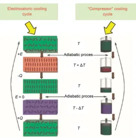
Theoretically, an ECE refrigerator working under a Carnot cycle can reach the highest possible efficiency, also named as Carnot efficiency. Figure 1 shows the comparison between VCR and Electrocaloric cooling cycles. As shown in Figure 1 for Electrocaloric cooling system, it is started with Electrocaloric materials under disordered state. When an external electric filed is applied, the materials tend to be transited into ordered state, which will release the energy in forms of heat during the transition process. After removing the electric filed, the materials will tend to become disorder again and this process requires the materials to ab-sorb the surrounded heat as energy to support the disorder-to-order transition process. In this way, a Electrocaloric cooling system is achieved. And a successful design of Electrocaloric cooling devices should form a similar cycle by utilizing the Electrocaloric temperature changes [6].
DOI: 10.4236/jectc.2017.73007 81 Journal of Electronics Cooling and Thermal Control
Figure 1. Comparison of Electrocaloric cooling cycle and “Compressor” cooling cycle.
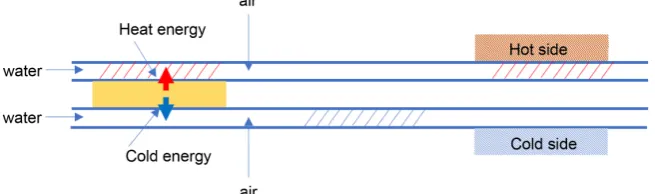
a functional EC system, the effeicient thermal transfer between EC materials and thermal ends requires a good thermal switch. A thermal switch is a functional thermal element that changes its thermal conductance in response to changes in thermal loading, and thereby helps maintain a target device or system to stay within desired temperature ranges. When a target device goes over a critical temperature, the switch turns on and dissipates heat to a cold surface. When the target device then returns to an acceptable temperature, the switch turns off. An ideal heat switch should meet the following needs: great on/off ratio, good sensi-tivity, and low specific heat.
Figure 2 shows the model of the cooling system using the Electrocaloric ef-fect, coupling with a thermal switch that consists of fluid (water with high spe-cific heat capacity as proposed). In this design, the Electrocaloric material’s temperature changes alternatively with the application/removal of an external electric field. The water/air gap passes through the Electrocaloric material pe-riodically. By synchronizing the frequency of the Electrocaloric electric field and water/air gap flow, the upper tunnel water is constantly heated and the lower tunnel is constantly cooled. When the water in the tunnel reaches the hot/cold side, heat exchange occurs, and the complete effect sees the heat being pumped from the cold side to hot side, while a directional heat transfer against the tem-perature gradient is achieved.
DOI: 10.4236/jectc.2017.73007 82 Journal of Electronics Cooling and Thermal Control
Figure 2. Design of electrocaloric cooling system.
Based on the analyses and modeling results, an optimized design of Electroca-loric cooling device will be presented.
COMSOL 5.2a is used for Multiphysics simulation. The initial parameters are shown as in Table 1.
The initial frequency is set at 1 Hz; thermal conductivity is at 0.12 W/m·K; Electrocaloric temperature change of the EC material is at 5 K; the thickness of water flow is 200 um; the thickness of the EC material is 200 um; and the liquid used for the thermal switch is water. The model illustrated here is a 1-D model. For simplification, let’s assume the length and height of the components to be 1cm. To quantify the quality of the model, the power of heat transfer, the change in temperature of the liquid, and the efficiency of the model are considered.
1) Frequency
The relationship between Frequency and the efficiency of EC devices is the first factor to be studied. The Temperature change of working fluids and cooling power are with various frequency as shown in Figure 3. As indicated from the
Figure 3, when the frequency increases, the efficiency of the model gradually decreases. When the frequency increases, the temperature change of water de-creases. When the frequency increases, the power of the model inde-creases.
The explanation behind these facts may be that when the frequency increases, not enough time will be left for the complete transfer of heat into the liquid, which can cause temperature changes along with efficiency decrease. However, as the frequency increases, the time gap between each transfer decreases, which causes the power of the model to increase. An optimal operation frequency is the result of balanced efficiency, with temperature change and cooling power. After taking all these factors into consideration, an operational frequency of 1 Hz is applied.
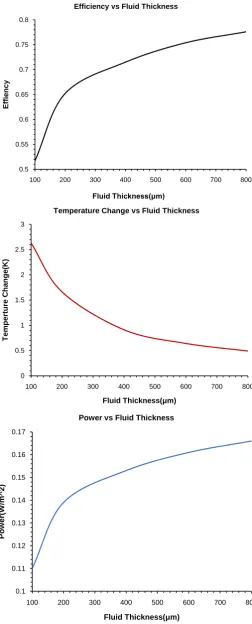
2) Thickness of water
DOI: 10.4236/jectc.2017.73007 83 Journal of Electronics Cooling and Thermal Control
Table 1. Initial parameters of simulation.
Name Expression Value Description
l_tube 20 [um] 2E−5m the length of the tube
l_water 200 [um] 2E−4m the length of water
l_air 200 [um] 2E−5m the length of air
dT 5 [K] 5 K change in temperature
l_EC 200 [um] 2E−4m the length of EC material
thermal conductivity 0.12 [W/m*K] 0.12 [W/m*K] thermal conductivity of EC
Figure 3. Efficiency, temperature change and power change as a function of operation frequency.
water decreases steeply at first, then its decrement is slowed down. When the thickness of water increases, the power of the model increases. This indicates that the increase of water thickness, meaning the increase in the volume of wa-ter, increases the efficiency and power, since the more water is implemented the more heat released by the EC material can be absorbed. The temperature change of water will decrease, when the mass of water increases.
0.35 0.4 0.45 0.5 0.55 0.6 0.65 0.7 0.75
0 1 2 3 4 5
E
ff
ici
en
cy
Frequency(Hz) Efficiency vs Frequence
0.8 1 1.2 1.4 1.6 1.8 2
0 1 2 3 4 5
T
e
m
p
e
rtu
re
C
h
a
n
g
e
(K
)
Frequency(Hz) Temperature Change vs Frequence
0 0.05 0.1 0.15 0.2 0.25 0.3 0.35 0.4
0 1 2 3 4 5
Po
w
e
r(
W
/m
^
2
)
DOI: 10.4236/jectc.2017.73007 84 Journal of Electronics Cooling and Thermal Control
Figure 4. Efficiency, temperature change and power change as a func-tion of fluid thickness.
0.5 0.55 0.6 0.65 0.7 0.75 0.8
100 200 300 400 500 600 700 800
E
ffi
e
n
c
y
Fluid Thickness(μm) Efficiency vs Fluid Thickness
0 0.5 1 1.5 2 2.5 3
100 200 300 400 500 600 700 800
T
e
m
p
e
rtu
re
C
h
a
n
g
e
(K
)
Fluid Thickness(μm) Temperature Change vs Fluid Thickness
0.1 0.11 0.12 0.13 0.14 0.15 0.16 0.17
100 200 300 400 500 600 700 800
Po
w
e
r(
W
/m
^
2
)
DOI: 10.4236/jectc.2017.73007 85 Journal of Electronics Cooling and Thermal Control
3) Thermal Conductivity of EC Materials
[image:8.595.253.496.112.698.2]As shown in the Figure 5, while high thermal conductivity of Electrocaloric
Figure 5. Efficiency, temperature change and power change as a function of thermal conductivity of EC materials.
0.5 0.55 0.6 0.65 0.7 0.75 0.8 0.85
0 0.2 0.4 0.6 0.8 1
E
ff
ici
en
cy
Thermal Conductivity of EC Materials(W/mK) Efficiency vs Thermal Conductivity
1.3 1.4 1.5 1.6 1.7 1.8 1.9 2 2.1 2.2
0 0.2 0.4 0.6 0.8 1
T
e
m
p
e
rtu
re
C
h
a
n
g
e
(K
)
Thermal Conductivity of EC Materials(W/mK) Temperature vs Thermal Conductivity
0.11 0.12 0.13 0.14 0.15 0.16 0.17 0.18 0.19
0 0.2 0.4 0.6 0.8 1
Po
w
e
r(
W
/m
^
2
)
DOI: 10.4236/jectc.2017.73007 86 Journal of Electronics Cooling and Thermal Control
materials can contribute to EC device performance, the heat generated/absorbed by the ECE requires high thermal conductivity for efficient transport. When the thermal conductivity of EC material increases, efficiency, temperature change of the water, and the power of the model all increases by approximately the same degree. As the thermal conductivity of the EC material increases, more heat can be conducted, which means the heat that transferred from the EC material to the water may be huge, and the process can occur more efficiently. This is made possible by higher temperature change of the liquid-water, the power, and high efficiency of the model. Hence, it can be concluded that it is meaningful to de-velop EC materials with high thermal conductivity to increase thermal treatment efficiency.
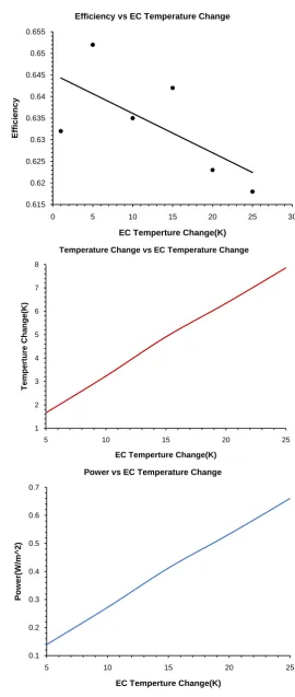
4) The Electric Field Applied
The level of EC temperature change is directly related to both material prop-erties and the voltage applied to the material. Scientists have put significant amounts of efforts to maximize EC temperature change. It has been reported that a temperature change of 50 K has been achieved using a composite material of PVDF based polymer and perovskite nanoparticle. However, high voltage has high requirement for the longevity and stability of EC materials to be used. It is interesting to study the relation between EC device performances (including to-tal device temperature change, power density and energy efficiency) and EC materials temperature change. As we can see from Figure 6, when the voltage of the electric field applied increases, the efficiency of the model generally decreas-es. When the voltage of the electric field applied increases, the increase of the water temperature and the power of the model is approximately linear. The in-crease of the applied electric field leads to immediate temperature change of the EC material. Thus, the temperature change of liquid water will increase, given that it will absorb more heat. Also, since the water absorbs more energy, the power and efficiency of the use water will also increase. The discrete dots in the first graph indicates that EC temperature change may not be an influential factor of the efficiency. Thus, some minor errors in the simulation may cause some da-ta fluctuation. This partially explains why there isn’t a positive correlation in the first graph above.
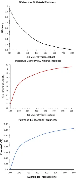
5) The Thickness of EC Materials
DOI: 10.4236/jectc.2017.73007 87 Journal of Electronics Cooling and Thermal Control
Figure 6. Efficiency, temperature change and power change as a func-tion of temperature change of EC materials.
0.615 0.62 0.625 0.63 0.635 0.64 0.645 0.65 0.655
0 5 10 15 20 25 30
E
ff
ici
en
cy
EC Temperture Change(K) Efficiency vs EC Temperature Change
1 2 3 4 5 6 7 8
5 10 15 20 25
T
e
m
p
e
rtu
re
C
h
a
n
g
e
(K
)
EC Temperture Change(K) Temperature Change vs EC Temperature Change
0.1 0.2 0.3 0.4 0.5 0.6 0.7
5 10 15 20 25
Po
w
e
r(
W
/m
^
2
)
DOI: 10.4236/jectc.2017.73007 88 Journal of Electronics Cooling and Thermal Control
Figure 7. Efficiency, temperature change and power change as a function of the thickness of EC materials.
0.2 0.3 0.4 0.5 0.6 0.7 0.8 0.9 1
100 200 300 400 500 600 700 800
E
ff
ici
en
cy
EC Material Thickness(μm) Efficiency vs EC Material Thickness
1.1 1.2 1.3 1.4 1.5 1.6 1.7 1.8 1.9 2 2.1
100 200 300 400 500 600 700 800
T
e
m
p
e
rtu
re
C
h
a
n
g
e
(K
)
EC Material Thickness(μm) Temperature Change vs EC Material Thickness
0.1 0.11 0.12 0.13 0.14 0.15 0.16 0.17 0.18
100 200 300 400 500 600 700 800
Po
w
e
r(
W
/m
^
2
)
EC Material Thickness(μm)
DOI: 10.4236/jectc.2017.73007 89 Journal of Electronics Cooling and Thermal Control
Table 2. EC device performance vs cooling fluids.
liquid Temperature change (K) Power (W/cm^2) efficiency
water 1.66 0.1393 0.651610549
glycerol 1.95 0.1178 0.551038928
engine oil 2.48 0.085 0.397608734
gasoline 2.44 0.079 0.369542235
EC thickness, the percentage of heat transferred from EC materials to the cool-ing fluid can be significantly decreased, which lowers the efficiency.
6) The Kind of Liquid Used
As shown from the Table 2 above, the use of gasoline in the place of cooling fluid can yield the greatest change in temperature, ceteris paribus, while the model that uses water yields the greatest power and best efficiency. The less the value of the specific heat a liquid has, the more temperature change may occur when the same type of electric field is applied.
4. Conclusion
In this paper, a compact cooling devices based on Electrocaloric materials has been designed. Factors which affect the performance of the thermal device have also been modeled and analyzed. Finite element simulation shows that a high ef-ficiency can be reached through stated model. It is expected that this study can be a guide for further research in the discovery of better EC materials.
References
[1] Hirasawa, S., Kawanami, T. and Shirai, K. (2016) Efficient Cooling System Using Electrocaloric Effect. Journal of Electronics Cooling and Thermal Control, 78. [2] Wilson, L. What Are the Major Uses of Electricity?
http://shrinkthatfootprint.com/how-do-we-use-electricity
[3] Plaznik, U., et al. (2015) Bulk Relaxor Ferroelectric Ceramics as a Working Body for an Electrocaloric Cooling Device. Applied Physics Letters, 043903.
[4] CIA World-Fact Book.
https://www.cia.gov/library/publications/the-world-factbook/
[5] Joule, J.P. (1859) On Some Thermo-Dynamic Properties of Solids. Philosophical Transactions, 149, 91. https://doi.org/10.1098/rstl.1859.0005
[6] Smith, A. (2013) Who Discovered the Magnetocaloric Effect? The European Physi-cal Journal, 38, 507-517. https://doi.org/10.1140/epjh/e2013-40001-9
[7] Mischenko, A.S., Zhang, Q., Scott, J.F., Whatmore, R.W. and Mathur, N.D. (2006) Giant Electrocaloric Effect in Thin-Film PbZr0.95Ti0.05O3. Science, 311, 1270-1271.
https://doi.org/10.1126/science.1123811
[8] Neese, B., Chu, B.J., Lu, S.G., Wang, Y., Furman, E. and Zhang, Q.M. (2008) Large Electrocaloric Effect in Ferroelectric Polymers Near Room Temperature. Science, 321, 821-823. https://doi.org/10.1126/science.1159655
Submit or recommend next manuscript to SCIRP and we will provide best service for you:
Accepting pre-submission inquiries through Email, Facebook, LinkedIn, Twitter, etc. A wide selection of journals (inclusive of 9 subjects, more than 200 journals)
Providing 24-hour high-quality service User-friendly online submission system Fair and swift peer-review system
Efficient typesetting and proofreading procedure
Display of the result of downloads and visits, as well as the number of cited articles Maximum dissemination of your research work
Submit your manuscript at: http://papersubmission.scirp.org/