ARTEFACT CONSISTENCY MANAGEMENT
Ildiko Pete
A Thesis Submitted for the Degree of PhD at the
University of St Andrews
2017
Full metadata for this item is available in St Andrews Research Repository
at:
http://research-repository.st-andrews.ac.uk/
Please use this identifier to cite or link to this item:
http://hdl.handle.net/10023/11032
Software Artefact Consistency
Management
Ildiko Pete
This thesis is submitted in partial fulfilment for the degree of
Doctor of Philosophy
at the University of St Andrews
Firstly, I would like to express my sincere gratitude to my supervisor, Dharini Balasubramaniam. You gave me the opportunity to challenge and improve myself, to focus my attention on exploring a problem, through which I did not only develop professional and technical skills; it has also shaped my world view and how I approach things in life. This has been one of the most valuable lessons. Thank you for your support and for providing me guidance throughout my time working with you. I would also like to say thank you to my secondary supervisor Juliana Bowles, and John Thomson, Alex Voss, Özgür Akgün, and Peter Nightingale, for their invaluable help.
Candidate’s Declarations
I, Ildiko Pete, hereby certify that this thesis, which is approximately 55000 words in length, has been written by me, that it is the record of work carried out by me and that it has not been submitted in any previous application for a higher degree. I was admitted as a research student and as a candidate for the degree of Doctor of Philosophy in October, 2012; the higher study for which this is a record was carried out in the University of St Andrews between 2012 and 2016.
Date:
Signature of candidate:
Supervisor’s Declaration
I hereby certify that the candidate has fulfilled the conditions of the Resolution and Regulations appropriate for the degree of Doctor of Philosophy in the University of St Andrews and that the candidate is qualified to submit this thesis in application for that degree.
Date:
In submitting this thesis to the University of St Andrews I understand that I am giving permission for it to be made available for use in accordance with the regulations of the University Library for the time being in force, subject to any copyright vested in the work not being affected thereby. I also understand that the title and the abstract will be published, and that a copy of the work may be made and supplied to any bona fide library or research worker, that my thesis will be electronically accessible for personal or research use unless exempt by award of an embargo as requested below, and that the library has the right to migrate my thesis into new electronic forms as required to ensure continued access to the thesis. I have obtained any third-party copyright permissions that may be required in order to allow such access and migration, or have requested the appropriate embargo below.
The following is an agreed request by candidate and supervisor regarding the electronic publication of this thesis:
Access to printed copy and electronic publication of thesis through the University of St Andrews.
Date:
Signature of candidate:
Contents i
List of Figures vii
List of Tables ix
Listings xi
1 Introduction 1
1.1 Problem Statement . . . 1
1.2 Motivation . . . 2
1.3 Scope . . . 4
1.4 Research Question and Hypotheses . . . 5
1.5 Novel Contributions . . . 6
1.6 Thesis Organisation . . . 7
1.7 Publications . . . 8
2 Background 9 2.1 Software Artefacts . . . 9
2.1.1 Definition . . . 9
2.1.2 Artefact Classification . . . 10
2.2 Traceability . . . 11
2.2.1 Definition, Significance and Terminology . . . 11
2.2.2 Trace Link Classification . . . 14
2.2.2.1 Existing Classifications . . . 14
2.2.2.2 Trace Link Classification of Heterogeneous Artefacts . . . 15
2.3 Change Impact Analysis . . . 16
2.3.1 Definition and Terminology . . . 16
2.3.2 Categorisation of Change Impact Analysis Techniques . . . 17
2.4 Consistency, Consistency Management, Consistency Checking and Change Propagation . . . 18
2.4.1 Consistency . . . 18
2.4.2 Consistency Management . . . 18
2.4.3 Artefact Consistency Management . . . 19
2.4.4 Consistency Checking . . . 19
2.4.5 Change Propagation . . . 19
2.5 Conclusion . . . 20
3 Literature Review 21 3.1 Introduction . . . 21
3.2 Methodology . . . 22
3.2.1 Planning . . . 22
3.2.1.1 Research Questions . . . 22
3.2.1.2 Search Process . . . 22
3.2.2 Execution . . . 23
3.2.3 Results Analysis . . . 24
3.2.4 Related Surveys . . . 24
3.3 Classification . . . 25
3.4 Review of State-of-the-art Solutions . . . 25
3.4.1 Holistic Solutions . . . 26
3.4.1.1 Maintaining Separate Artefacts . . . 26
3.4.1.2 Combining Artefacts . . . 34
3.4.2 Solutions Addressing Specific Aspects of Consistency Management . . 36
3.4.2.1 Traceability Techniques . . . 36
3.4.2.2 Change Impact Analysis (IA) Approaches . . . 41
3.4.2.3 Consistency Checking and Change Propagation Approaches . 42 3.5 Evaluation . . . 44
3.6 Conclusions . . . 45
4 Holistic Artefact Consistency Management Framework 47 4.1 Challenges of Artefact Consistency Management . . . 47
4.2 An Ideal Consistency Management Framework . . . 49
4.3 Proposed Approach: Concept of a Holistic Artefact Consistency Management Framework . . . 50
4.3.1 Definition . . . 50
4.3.2 Illustrative Example . . . 52
4.3.3 Real World Applicability of the Holistic Approach . . . 54
4.4 Data Representation . . . 54
4.4.1 Conceptual Data Model . . . 55
4.4.1.1 Property Graph Structure . . . 55
4.4.1.2 Alternative Artefact and Trace Link Representations . . . 57
4.4.1.3 Evaluation of the Property Graph Model . . . 58
4.4.2 Bridging the Gap Between Heterogeneous Artefacts and the Property Graph Model . . . 58
4.5 Framework Stages . . . 59
4.5.1 Change Detection . . . 60
4.5.1.1 Artefact Change Classification . . . 60
4.5.1.2 Change Detection Output: Change Data . . . 62
4.5.2 Rule-based Traceability Maintenance . . . 62
4.5.3 Change Impact Analysis . . . 63
4.5.5 Change Propagation . . . 65
4.6 Conclusions . . . 65
5 Architecture and Design 69 5.1 Design Strategy . . . 69
5.1.1 Functional Requirements . . . 69
5.1.2 Design Constraints . . . 70
5.1.3 Architectural Tactics . . . 70
5.2 Framework Architecture . . . 71
5.3 Detailed Design of Architectural Components . . . 73
5.3.1 Data Access Layer and Data Store components . . . 73
5.3.1.1 Data Store . . . 73
5.3.1.2 Data Access Layer . . . 73
5.3.2 External Repository and Corresponding API Component . . . 74
5.3.3 Logic layer and its Components . . . 75
5.3.3.1 Interaction Manager . . . 75
5.3.3.2 Traceability Manager . . . 75
5.3.3.3 Setup Manager . . . 75
5.3.3.4 Consistency Manager . . . 76
5.4 Design Evaluation . . . 78
6 Implementation of the ACM Framework: Data Representation 81 6.1 Introduction . . . 81
6.2 Artefact Selection . . . 82
6.3 Property Graph Representation . . . 82
6.3.1 Specification of Graph Nodes and Properties . . . 84
6.3.1.1 Requirement Specification . . . 84
6.3.1.2 UML Design Diagram: Use Case diagram . . . 85
6.3.1.3 Software Architecture: Conceptual view . . . 86
6.3.1.4 Software Architecture: Module view . . . 86
6.3.1.5 UML Design Diagram: Class diagram . . . 87
6.3.1.6 UML Design Diagram: Sequence diagram . . . 88
6.3.1.7 Java source code . . . 90
6.3.1.8 JUnit test . . . 90
6.3.1.9 Element Hierarchy: Container and Member Elements . . . . 90
6.3.2 Specification of Graph Edges and Properties . . . 90
6.3.3 Conclusions . . . 91
6.4 Bridging the Gap between Heterogeneous Artefacts and the Property Graph Model 92 6.4.1 Artefact Data Extraction . . . 92
6.4.1.1 Tools . . . 92
6.4.1.2 Extraction . . . 93
6.4.2 Transformation . . . 94
6.4.2.1 Transformation: GraphML . . . 94
6.4.2.2 Transformation: XSLT . . . 96
6.4.2.4 Extracting and Transforming Trace Links . . . 97
6.4.2.5 Transformation Summary . . . 101
6.4.3 Graph Data Persistence . . . 101
6.4.3.1 Graph Databases . . . 102
6.4.3.2 Alternative Strategies . . . 103
6.4.3.3 Neo4j . . . 104
6.5 Conclusions . . . 105
7 Implementation of the ACM Framework: Framework Stages 109 7.1 Introduction . . . 109
7.2 Change Detection . . . 109
7.2.1 Specifics of Changes . . . 111
7.2.2 Identification of theFile LevelChange Type . . . 112
7.2.3 Identification of theArtefact Element LevelChange Type . . . 113
7.2.3.1 Change Identification and Representation: XML . . . 113
7.2.3.2 Change Identification and Representation: Graph-based Ap-proach . . . 114
7.2.4 Change Detection Output: Change Data object . . . 119
7.2.5 Conclusions . . . 120
7.3 Rule-based Traceability Maintenance . . . 120
7.3.1 Delete File Level Change . . . 120
7.3.2 Add File Level Change . . . 122
7.3.3 Edit File Level Change . . . 122
7.3.3.1 Delete Artefact Element Level Change . . . 122
7.3.3.2 Add Artefact Element Level Change . . . 123
7.3.3.3 Edit Artefact Element Level Change . . . 123
7.4 Change Impact Analysis . . . 124
7.4.1 Illustrative Example . . . 125
7.5 Rule-based Consistency Checking . . . 126
7.5.1 Inter Consistency Checking . . . 127
7.5.2 Intra Consistency Checking . . . 128
7.5.3 Rule Implementation . . . 129
7.5.4 Output . . . 129
7.6 Change Propagation . . . 129
7.6.1 Graph Database Update . . . 130
7.6.2 Inconsistency Resolution . . . 130
7.6.3 Final Output of Consistency Management . . . 130
7.7 Implementation Evaluation and Conclusions . . . 131
8 Automating Traceability Creation using Machine Learning 133 8.1 Introduction . . . 133
8.2 Machine Learning . . . 134
8.2.1 Basic Concepts . . . 134
8.2.2 Relevant Machine Learning Usage Scenarios . . . 135
8.2.4 Traceability Creation as a Classification Problem . . . 136
8.3 Data Collection . . . 137
8.3.1 Criteria for Candidate System Selection . . . 137
8.3.2 Candidate Systems . . . 138
8.4 Data Preparation . . . 139
8.4.1 Establishing Positive Instances - Trace Links . . . 140
8.4.2 Establishing Negative Instances - Generating Data for Representing Non-Relations . . . 142
8.5 Feature Selection . . . 143
8.6 Model Selection . . . 144
8.7 Methodology . . . 147
8.7.1 Training . . . 147
8.7.2 Model Evaluation . . . 147
8.8 Results and Discussion . . . 149
8.9 Integration in the Framework . . . 152
8.10 Conclusions . . . 152
9 Evaluation 153 9.1 Evaluation Objectives . . . 153
9.2 Evaluation Questions . . . 154
9.3 Evaluation Design . . . 155
9.3.1 Research Method Selection . . . 155
9.3.1.1 Evaluation of Hypotheses . . . 155
9.3.1.2 Correctness testing . . . 156
9.3.1.3 Performance Evaluation . . . 158
9.3.2 Data Collection . . . 159
9.3.2.1 Selecting a Data Collection Technique . . . 159
9.3.2.2 Selecting Particular Open Source Systems . . . 159
9.3.2.3 Change Selection . . . 160
9.3.2.4 Artefacts Obtained from Open Source Systems . . . 160
9.4 Methodology and Results . . . 160
9.4.1 Methodology: Testing Correctness . . . 160
9.4.1.1 Framework Setup Scenario . . . 160
9.4.1.2 Consistency Management Scenario . . . 164
9.4.2 Methodology: Evaluation of Hypotheses . . . 169
9.4.2.1 Q1 - Tool and methodology independence . . . 169
9.4.2.2 Q2 - Automation . . . 170
9.4.2.3 Q3 - Artefact Independence . . . 171
9.4.3 Methodology: Performance Tests . . . 172
9.4.4 Limitations and Threats to Validity . . . 177
9.5 Conclusions . . . 178
10 Conclusions 179 10.1 Summary . . . 179
10.2.1 Assessment in the Context of Requirements . . . 180
10.2.2 Limitations . . . 181
10.3 Future Work . . . 182
10.4 Concluding Remarks . . . 185
Appendix A Appendix - A Performance results 187
Appendix B Appendix B - Summary Tables 191
1.1 Differential evolution of software artefacts. . . 3
2.1 Trace link connecting a source and a target artefact. . . 13
3.1 Classification of solutions contributing to artefact consistency management. . . 26
4.1 Holistic artefact consistency management theoretical framework process diagram. . 51
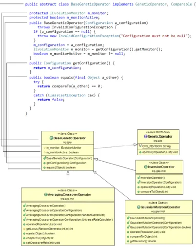
4.2 JGAP system class diagram and source code excerpt. . . 53
4.3 Illustration of the property graph model. . . 57
4.4 Bridging the gap between heterogeneous artefacts and the property graph model. . 59
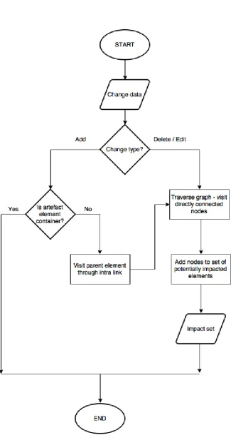
4.5 Flow chart illustrating the algorithm for inter link traversals. . . 67
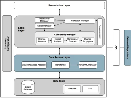
5.1 The overall architecture of the ACM framework. . . 71
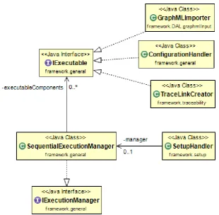
5.2 Design of setup management functionality, class diagram excerpt. . . 76
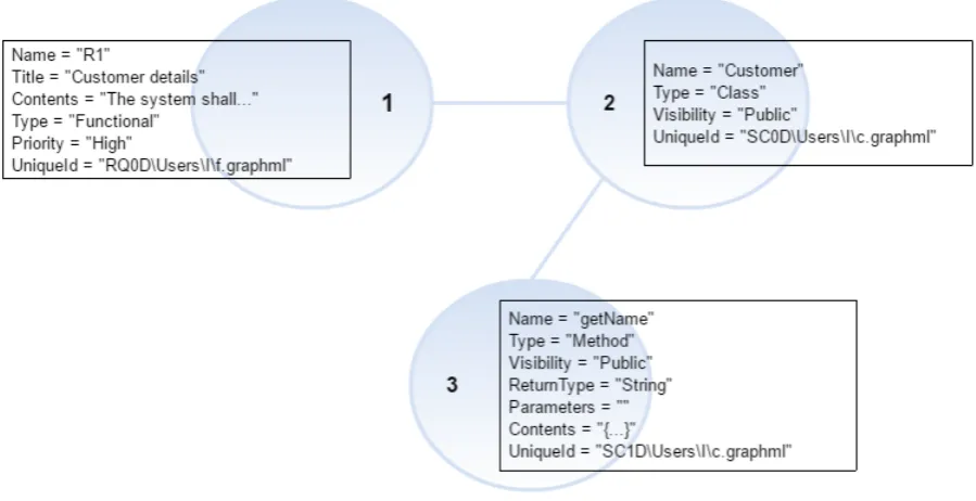
5.3 Design of the orchestration of change detection functionality, class diagram excerpt. 77 6.1 Property graph representation of a requirement, a Java source code class, and a Java method artefact element. . . 85
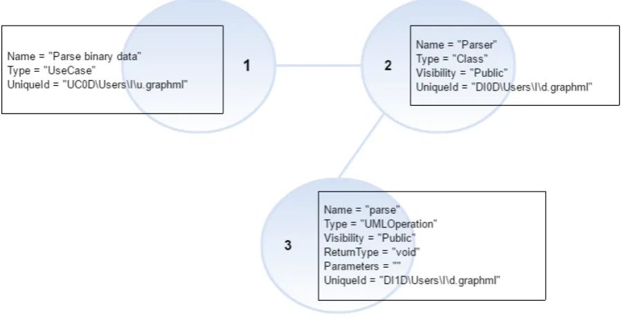
6.2 Binary Block Parser system - Use case diagram excerpt. . . 85
6.3 Property graph representation of a single use case, a UML class and a UML operation. 86 6.4 Architecture diagram of Titan . . . 87
6.5 Property graph representation of a single architectural component, and a UML class and operation. . . 87
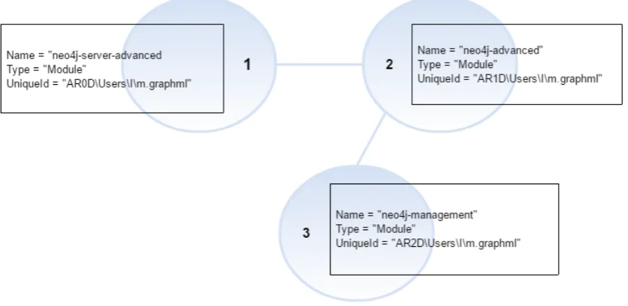
6.6 Module view architecture of Neo4j - Excerpt. . . 88
6.7 Property graph representation of three architectural modules. . . 88
6.8 Example UML classParserand its member methodparse. . . 89
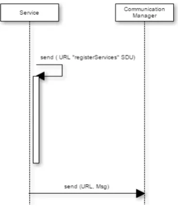
6.9 Sequence diagram fragment from the MyRobotLab system. . . 89
6.10 Property graph representation of theServiceLifeline element. . . 89
6.11 Artefact data extraction. . . 94
6.12 The Account UML class and its members. . . 96
6.13 Mapping heterogeneous XML schemas to a uniform schema to represent artefact data.101 6.14 Artefact and trace link data in Neo4j. . . 106
6.15 Framework setup functionality. . . 107
7.1 Change detection overview. . . 110
7.2 Nestedhashmaprepresentation of graph nodes and their properties. . . 117
7.3 Graph data representing Java source code and UML class diagram nodes. . . 121
7.4 Delete file level change. . . 121
7.5 Delete element from artefact. . . 123
7.6 Add new element to artefact. . . 123
7.7 Edit property of an existing element. . . 124
7.8 Example artefact property graph to illustrate the change impact analysis approach. . 125
8.1 Accuracy results of the J48, Multilayer Perceptron, Naive Bayes, SMO, and ZeroR classifiers. . . 149
8.2 Cross-validation results: each system is used as a test set. . . 151
9.1 Framework Setup execution time (s) and system size. . . 175
9.2 Framework Setup execution time (s) and artefact size. . . 176
2.1 Artefact Categorisation Examples. . . 12
4.1 Evaluation of the suitability of the property graph model for artefact data representation. 58 4.2 Artefacts to be represented in the framework by a property graph model. . . 59
4.3 Artefact consistency management process inputs and outputs. . . 60
5.1 Mapping of functional areas to architectural components. . . 78
6.1 Categorisation of artefact elements based on their hierarchical relationships. . . 91
6.2 Property key/value pairs used in the framework. . . 97
6.3 Transformation output summary. . . 98
7.1 Summary of actions taken depending on the file level change type. . . 111
8.1 Comparison of candidate systems. . . 139
8.2 Extracted artefacts. . . 139
8.3 Feature vectors. . . 145
8.4 Training data. . . 147
8.5 Cross-validation: Systems highlighted in white are used for testing. . . 148
8.6 Accuracy of the Multilayer Perceptron, J48, SMO and Naive Bayes classifiers using different feature combinations. . . 150
9.1 Derivation of evaluation questions and methods from the hypotheses and requirements.154 9.2 Functionality areas, inputs and expected outputs. . . 157
9.3 The number of artefacts obtained from each open source system. . . 161
9.4 Summary of Framework Setup results. . . 163
9.5 Summary of artefact element level change combinations in Java source code, JUnit test, and UML class diagram artefacts. . . 165
9.6 Summary of Consistency Management test scenarios and results. . . 166
9.7 Tools used in the design or development of selected subject systems. . . 170
9.8 Automation level of Framework stages and Artefact Data setup. . . 171
9.9 Test environment properties. . . 173
9.10 Performance tests - methodology. . . 174
A.1 Framework Setup execution times using the MazeSolver, MyRobotlab and JBBP systems. . . 187
A.2 Framework Setup execution times using the Service class (MyRobotLab), the Owner interface (Neo4j), and the JBBPToken class (JBBP). . . 188
A.3 Change identification algorithm execution times using the Owner interface of the Neo4j system. . . 188 A.4 Change identification algorithm execution times using the Service class of the
MyRobotlab system. . . 189 A.5 Change detection execution times using the JGAP system. . . 189 B.1 Comparison summary, Part I. The reviewed solutions are listed by their names
(where the name of the implemented system or project title is in place) or by the authors’ names. . . 192 B.2 Comparison summary, Part II. The reviewed solutions are listed by their names
(where the name of the implemented system or project title is in place) or by the authors’ names. . . 193 B.3 Comparison summary, Part III. The reviewed solutions are listed by their names
(where the name of the implemented system or project title is in place) or by the authors’ names. . . 194 B.4 Comparison summary, Part IV. The reviewed solutions are listed by their names
(where the name of the implemented system or project title is in place) or by the authors’ names. . . 195 B.5 Summary of artefacts handled by the framework and the derivation of property graph
nodes and their attributes from structural elements. . . 196
B.6 DeleteandAdd File Levelchanges - specific examples. . . 197
B.7 Artefact element levelchanges. . . 198
B.8 Delete file levelchange - Derivation of consistency rules based on the modified entity,
the connected entity, andinterlink type. Part I. . . 199
B.9 Delete file levelchange - Derivation of consistency rules based on the modified entity,
the connected entity, andinterlink type. Part II. . . 200
B.10 Delete file levelchange - Derivation of consistency rules based on the modified entity,
the connected entity, andinterlink type. Part III. . . 201
B.11 Edit file levelchange -Delete artefact element levelchange - Derivation of inter rules.202
B.12 Edit file levelchange -Add artefact element levelchange - Derivation of inter rules. 203
B.13 Edit file levelchange -Edit artefact element levelchange - Derivation of inter rules
part I. . . 204
B.14 Edit file levelchange -Edit artefact element levelchange - Derivation of inter rules
part II. . . 205 B.15 Derivation of intra consistency rules. . . 206 B.16 Trace maintenance rules in the delete file level change scenario for each artefact type.207 B.17 Trace maintenance rules in the delete artefact element level change scenario for each
artefact type. . . 208 B.18 Trace maintenance rules in the edit artefact element level change scenario for each
6.1 Java source code excerpt of a class with a field and getter method. . . 90 6.2 Example GraphML file modelling a UML class diagram and its property graph
representation. . . 95 6.3 An example inter trace link expressed in XML. . . 98 7.1 GraphML file, versionn- mapping to key-value pairs . . . 115 7.2 GraphGdefined as a collection of key-value pairs . . . 115 7.3 GraphG’defined as a collection of key-value pairs . . . 115 7.4 GraphML file, versionn+1- mapping to key-value pairs . . . 116 7.5 ExampleChangeDataobject . . . 120 7.6 String representation of impact analysis output. . . 126 7.7 Excerpt of XML rules capturing consistency rules. . . 129
1
C
HAPTER
O
NE
I
NTRODUCTION
1.1
Problem Statement
Evolution is an inherent characteristic of software systems. Software may be subject to modifications for a number of reasons including improving its performance, correcting and preventing faults and adapting to external changes [1]. Measuring the cost and effort of software maintenance has been the subject of studies as far back as the 1970s [2]. An often quoted figure shows that at least 60% of software development costs is spent on software maintenance [3]. Therefore the management of changes and the evolution of software systems have been extensively investigated through various disciplines with the aim of improving the maintainability of software. These research themes address different aspects of software evolution and include process models, tools supporting software evolution, and versioning systems [4] [5] [6]. Software evolution affects the complexity of the given system and has implications for software quality [7].
The effects of software evolution are exacerbated by the heterogeneous nature of entities representing software systems: the software development process produces artefacts expressed in various forms, such as source code, design diagrams, and requirement documents in natural language. All these artefacts represent the same system, at different levels of abstraction [8]. The evolution of software therefore can be described as the evolution of all of these artefacts [9]. In an ideal scenario, modifications to any of the artefacts will result in other related artefacts also being changed accordingly.
In practice however, software entities evolve at different paces and times. Research on software evolution has not yet adequately addressed the issue ofthe differential evolution of software artefacts, which is the focus of this work. The lack of synchronisation results in artefacts evolving inconsistently, where one representation reflects the latest changes, whilst related
artefacts may mirror previous versions, and contain possibly invalid information. A common scenario involves changes being applied to source code while other artefacts are not updated. Such practices can result in an ever growing drift between the different representations. A simplified version of the problem is illustrated by Figure 1.1, which depicts a scenario where three specific types of artefacts - requirements specification, UML class diagram and Java source code - evolve inconsistently. Versions marked in red are inconsistent. The first consistency issue is presented by version 1 (V1) of the requirement specification, which is not modified following the creation of version 2 (V2) of the UML class diagram. Both version 2 (V2) and 3 (V3) of the Java source code conform to version 2 of the UML diagram. The second consistency issue is shown by version 2 of the UML class diagram, which is not updated to reflect Java source code changes, i.e. the creation of version 4 (V4) of the Java source code.
1.2
Motivation
The consequences of the differential evolution of software artefacts can be summarised as follows. Inconsistent artefacts do not accurately represent the software system, and consequently stakeholders may develop a lack of trust in them. Outdated artefacts also hinder effective communication and collaboration, which poses significant challenges in distributed development scenarios. Additionally, not maintaining the consistency of diverse representations impedes the effective understanding of the system. These issues reduce the evolvability [10] of systems and present obstacles to software maintenance.
Considering the efforts associated with maintaining software systems, it is apparent that the cost of such inconsistencies is not negligible. On the other hand, managing the consistency of artefacts is likely to lead to more easily maintainable systems fulfilling their intended purpose. Various research areas within software engineering have contributed to addressing the problem of disconnected and inconsistently evolving artefacts from different perspectives. These areas include, for example,Requirements Engineering, Software Processes, Software Change
Management (Impact analysis, Software Configuration Management), and Computer-Aided
Software Engineering (CASE).
Figure 1.1:Differential evolution of software artefacts.
highlights the fact that the multitude of lifecycle tasks, tools and artefacts pose significant challenges.
Requirements engineeringis the process of establishing what services the software should provide,
and is concerned with analysing whether requirements are testable, properly understood and have clearly stated origins [12]. A key problem in requirements engineering is the management of inevitable changes. The ability to create and maintain links both between requirements themselves and other artefacts can be particularly useful in tackling this issue, which has not been adequately addressed to date.
Since changes cannot be eliminated, a viable solution that can accommodate them in a consistent manner is required. Severalsoftware engineering process models have emerged over the past decades aimed at providing a framework for supporting the steps of the development process. Incremental development strategies aim to eliminate the disadvantages of sequential models, such as late design breakage. Dividing the system into units of functionality based on subsets of requirements and delivering this functionality in increments form the core of this approach, providing the benefits of a more refined system at the end of the development process [6]. Being able to identify the impact of a change in one artefact on another requires establishing links between them. However, current processes do not enforce artefact linking and in most software development scenarios software artefacts stay disconnected and go through stages of refinement without considering dependent entities [13].
Besides minimising the challenges caused by modifications, an important aspect of effective
carried out by configuration management [14] [15]. Policies and standards, such as Capability Maturity Model Integration (CMMI) steps for configuration management [16], aid change control tasks by specifying their main elements including the identification of configuration items (artefacts) or tracking change requests. Abiding by such practices facilitates the consistent evolution of software artefacts. However the individual tasks involved, which are often tedious and error-prone, in an ideal scenario should be supported in an automatic manner and by a single solution catering for all aspects of the problem.
1.3
Scope
This thesis investigates the feasibility of a holistic consistency management approach to handle the differential evolution of heterogeneous software artefacts. The central claim of this work is that the consistency of heterogeneous software artefacts can be managed in a single framework, independent of representations, tools and methodologies, based on an approach that supports the automation of traceability creation, change detection, change impact analysis, consistency checking and change propagation, and is guided by the principles of extensibility and minimal intrusion to user practices. The proposed approach aims to complement development methodologies such as spiral and agile, and to support artefacts produced in traditional and agile software development.
The approach is realised in a proof-of-concept system, theArtefact Consistency Management (ACM) framework. ACM provides semi-automatic traceability creation and change propagation, and automatic change detection, impact analysis and consistency checking functionality to manage the consistent evolution of requirements specification, UML class diagram, Java source code, JUnit test case, UML sequence diagram, UML use case diagram, and software architecture (conceptual and module view) artefacts. These artefacts are selected for the current implementation as they represent various lifecycle stages and abstraction levels. However, the ACM framework is designed to be extensible and to allow new artefacts to be added. Finally, the framework is evaluated using six open source systems.
Inconsistently evolving artefacts is a significant issue which has been discussed in both the
ViewPoint-oriented software developmentliterature and theModel Driven Architecture (MDA)
community. While a summary of the main commonalities and differences between the approach presented in this work and these areas is provided, it is outwith the boundaries of this research to discuss their specifics in detail.
ViewPoint-oriented software development refers to the problem as the multiple perspectives
differing development strategies", and aims to provide a framework for managing these perspectives. The resulting ViewPoints framework offers an infrastructure for supporting multiple methods and views in a distributed, collaborative software development setting, through integrating existing software development tools and methods [17]. Integration constitutes the primary difference between theViewPoints frameworkand this work, which aims to provide an artefact and tool independent solution. Additionally, multiple-perspectives software development requires a method engineering process to take place, for example, to construct ViewPoints templates through which additional ViewPoints can be created [17].
MDAis a framework for software development, in which different representations of a system are referred to as models [18]. The steps of software development include specifying Platform Independent and Platform Specific models, which are transformed to code [19]. The issue of inconsistency emerges as a result of changes. MDAspecifies a methodology to carry out software development tasks, while the work presented in this thesis aims to explore an approach to provide support to manage the evolution of software artefacts as part of existing software development activities. However, the ACM framework does not preclude the use of MDA and MDA specific models.
1.4
Research Question and Hypotheses
This thesis poses the following research question:
Is it feasible to handle the differential evolution of heterogeneous software artefacts auto-matically without imposing specific methodologies or tools and in an artefact independent manner?
Answering this question entails the identification of the tasks involved in handling the evolution of heterogeneous artefacts, and the investigation of an achievable level of automation and a suitable representation of diverse software artefacts. To answer this research question, the following hypotheses are investigated:
H1. The differential evolution of heterogeneous software artefacts can be handled by one holistic consistency management framework. Currently no single approach offers a full solution to manage the consistency of software artefacts. The feasibility of this hypothesis is investigated through the design and implementation of such a holistic framework, the concept of which is introduced in Chapter 4.
artefacts often prescribe the processes to be followed and tools to be used. This is a restrictive approach considering the multitude of representations, tools and the diversity of projects.
H3. It is possible to automate all aspects of artefact consistency management. This work hypothesises that some aspects can be fully automated, while others may require manual effort, and hence can be partially automated.
H4. An artefact consistency management framework can be independent of specific artefacts: it can cater for heterogeneous software artefacts and can be extended to handle any new artefacts given that data contained in them can be accessed.
1.5
Novel Contributions
1. A survey and classification of approaches (see Chapter 3) relevant to the discussion of artefact consistency management. The survey reveals which research areas contribute to addressing the problem, and through an evaluation it identifies potential shortcomings. Based on the findings of the survey a set of challenges and characteristics of an ideal consistency management solution are derived (see Chapter 4) from which high level requirements of a consistency management framework are formed (see Chapter 4).
2. A holistic conceptual approach to support artefact consistency management incorporating traceability creation, change detection, impact analysis, consistency checking and change propagation (see Chapter 4).
3. The design, implementation and evaluation of a proof-of-concept prototype, the ACM framework1, which provides:
• An extensible, property-graph based representation of heterogeneous software artefacts • Automated support to transform heterogeneous representations to a unified graph-based
format, using XSLT transformations • Change detection functionality to support
a) The extraction of changes from an external repository
b) The identification of changes at the property graph level using a graph-based change identification algorithm
• Graph-based change impact analysis of heterogeneous software artefacts
• Extensible XML consistency rule base to support consistency checking of heterogeneous software artefacts
• A set of heterogeneous software artefacts obtained from six open source systems used for evaluation
These contributions are discussed in Chapter 5, 6 and 7.
4. An approach to automate trace link creation between heterogeneous software artefacts using machine learning (see Chapter 8).
5. A data set containing 1100 data instances representing trace links between UML diagram (use case, sequence diagram, class diagram), Java source code, JUnit test case, and software architecture (module view and conceptual view) artefacts. The data set provides a foundation for conducting traceability experiments for heterogeneous artefacts using machine learning and can be found at: https://github.com/ACMFramework/ACMTraceability.
6. A trace link classification, which is utilised in the ACM framework (see Chapter 2). 7. A categorisation of heterogeneous software artefacts (see Chapter 2).
1.6
Thesis Organisation
Chapter IIprovides a discussion of concepts relevant in the discussion of artefact consistency management.
Chapter IIIpresents a survey of related work. These solutions are classified and subsequently evaluated.
Chapter IVdescribes the proposed solution, and the concept of the holistic view of artefact consistency management.
Chapter Vpresents the overall architecture and design of the prototype (ACM) framework.
Chapter VIdiscusses the data representation strategy of ACM framework.
Chapter VII describes the implementation approach of each framework stage in the ACM framework.
Chapter VIIIintroduces a machine learning based approach to automate trace link creation between heterogeneous artefacts.
Chapter IX provides an evaluation of the proposed framework to assess feasibility and to demonstrate the effectiveness of the solution in fulfilling the requirements set out.
1.7
Publications
I. Pete and D. Balasubramaniam, "Handling the Differential Evolution of Software Artefacts : a Framework for Consistency Management," in Paper presented at 22nd IEEE International Conference on Software Analysis, Evolution, and Reengineering, 2015, pp. 599-600.
Works in Progress
Towards a Holistic Artefact Consistency Management Framework
Article manuscript submitted for publication to Automated Software Engineeringin October, 2016.
A Survey of Artefact Consistency Management
2
C
HAPTER
T
WO
B
ACKGROUND
This chapter introduces the terminology relevant in the discussion of artefact consistency management, which is derived from established research areas. Firstly, the concept of software artefacts is introduced and a classification of artefacts is provided. Subsequently, traceability is defined and a classification of trace links is supplied, which is followed by a description of change impact analysis. Lastly, definitions of consistency, consistency management, consistency checking and change propagation are discussed.
2.1
Software Artefacts
2.1.1
Definition
The termartefactis used both in industry and academia to refer to entities representing a software system. The context in which the concept primarily appears in industry is that of configuration management. Software artefacts can be thought of as information container units, and can be described by a number of attributes, such as actors creating or consuming them. Artefacts also have a state and a lifecycle, and a significant aspect of them is that they can be linked to other artefacts [20].
Finkelstein et al. define software artefacts as follows: "The (sub)-products and ’raw material’ of a process. An artefact produced by a process may later be used as a raw material by the same or a different process to produce other artefacts. Artefacts are often persistent and versioned. An aggregate of software artefacts to be delivered to a user is called a software product" [17]. Another definition by Beyer and Noack highlights the fact that there is a diverse range of software artefacts that constitute a software system ranging from documentation through test cases to source code [21].
In this work software artefacts are defined as products of the activities involved in software development. Due to the variety of these lifecycle activities the resulting artefacts show a high level of heterogeneity. Heterogeneous representations may also be managed by different tools, such as Microsoft Word1, Axiom2, Rational Rose3, Microsoft Visual Studio4, Eclipse5, TestLink6.
2.1.2
Artefact Classification
In the following section we propose a classification of software artefacts capturing the variety of dimensions through which a system can be represented. The categorisation is based on the following:
1. Aim and scope of artefacts: this aspect indicates whether the artefact is aimed at describing the system at a high level to allow stakeholders to communicate design decisions, such as an architecture diagram, or it captures low-level implementation details, such as source code. Thus, categories may include specification artefacts, communication artefacts, and implementation artefacts among others.
2. Process methodology and life cycle stage: each stage in the software life cycle has a well-defined purpose and produces specific artefacts. In a conventional waterfall life cycle [12], the analysis phase produces analysis artefacts, which can take multiple forms depending on the given project. For example, the results of analysis can be expressed through natural language requirements specifications, or equally, UML use cases. During design, typically architecture and design artefacts are created, such as design diagrams or architectures represented by Architecture Description Languages (ADL). The implementation phase may produce source code items or an executable (implementation artefacts). Testing may result in unit tests expressed in source code or test cases in a test management system (test artefacts). Finally, an artefact typically associated with the maintenance phase is an issue, a bug, or an item in a bug tracking system (maintenance artefacts).
Agile practices [12] may result in new artefact types as they structure the software life cycle in a different manner. A notable difference when compared to the waterfall life cycle is the reduction of effort spent on upfront specification. For example, product backlogs produced during the project planning phase may capture requirements, and features, user stories or use
1https://products.office.com/en-gb/word 2http://www.iconcur-software.com
3http://www-03.ibm.com/software/products/en/ratirosefami 4https://www.visualstudio.com/
cases may replace rigorous documentation (analysis artefacts). Each sprint produces source code and tests (implementation and test artefacts), and may also be accompanied by design diagrams capturing parts of the system (design artefacts).
3. Specific artefact structure: certain artefacts are characterised by a well-defined structure, such as source code built up from language constructs abiding by specified syntax rules. On the other hand, some artefacts, such as requirements specifications, do not necessarily exhibit a pre-defined structure to be rigorously followed across artefacts of the same type. Therefore, their structural elements may be shaped by authors’ preferences and decisions. Another consideration is whether the structure of artefacts is hierarchical or flat.
4. Abstraction level: artefacts can be characterised by their abstraction level, which indicates the level of detail they capture. In this work, a relative scale is used to compare artefacts to identify whether they represent a lower or a higher abstraction level when compared to another one. The highest abstraction level is exemplified by requirement specifications, while an instance of the lowest abstraction level relevant in this discussion is source code, for example.
The variety of representations is further expanded by the different sub-types. For example, source code can take various forms; high-level programming languages can be grouped into categories based on the programming paradigm [22] they follow, and a single category may include multiple programming languages which differ in features they provide. Most artefact types can be categorised in multiple ways, which is illustrated by examples given in Table 2.1.
2.2
Traceability
In this section the definition of traceability used in this work, the description of traceability-related concepts, and a classification of trace links are presented.
2.2.1
Definition, Significance and Terminology
A key aspect of software change management is the ability to understand relationships among software artefacts. In a typical software project, a large number of artefacts may exist and the specification of relationships among them is a complex and challenging task. The area of traceability is concerned with the specification and maintenance of such links.
Artefact Type Categorisation and Examples
Source code Based on programming paradigms [22], for example
Imperative: C Declarative: SQL Event-driven: Javascript Functional: Haskell
UML design diagrams Based on a classification proposed by Rumbaugh et al. [23], for example
Structural: class diagram, collaboration diagram Dynamic: state machine diagram, activity diagram Physical: deployment diagram
Model management: package diagram
Architecture diagrams Based on architectural views [24], for example
Logical view architecture Development view architecture Process view architecture
Table 2.1:Artefact Categorisation Examples.
to describe and follow the life of a requirement, in both a forwards and backwards direction" [26]. For the purposes of this work, a more generic definition of software traceability is proposed:
traceability refers to the ability to interrelate heterogeneous software artefacts representing a
software system at different abstraction levels.
Although traceability has been described as a quality attribute of software systems [27] and is required for compliance with certain industry standards [28] [29] [30], it is not characterised by broad acceptance and wide adoption in industry. In 1994, this problem was attributed to the lack of a common definition of traceability and the diverse user, project, task and information requirements [31]. The so called traceability problem [26] continues to exist in the present, where reasons for the lack of industry-wide adoption include costs and efforts associated with implementing traceability techniques. Current approaches may not offer a desirable level of accuracy and coverage, which also impedes their adoption.
of implementation. A major contribution of traceability is in the area of software maintenance, where links connecting entities aid the identification of parts of a system affected by a change. Specifically, it supports software change impact analysis [33], which is discussed in detail in Section 2.3. As traceability relations indicate dependencies between software artefacts, these relationships also support a number of other tasks such as understanding rationale and design decisions [34].
Following is a brief summary of fundamental traceability concepts, which are used throughout this thesis. The definitions are adopted from the work of Gotel et al. [25].
Trace link. An association between two artefacts as denoted by Figure 2.1. The illustration also shows that trace links are effectively bidirectional as they can be traversed in two directions. Besides the above definition, we define trace links as a pairPof a source and a target. Source and target are elements of the set of artefact elements.
Source and Target artefacts. The two ends of the association describing the origin and the destination of the trace link. In this work, artefacts may also be referred to as representations.
Figure 2.1:Trace link connecting a source and a target artefact.
Trace artefact type. As mentioned in Section 2.1.2, artefacts can be grouped based on similar characteristics they share.
Trace. "A specified triplet of elements", which consists of the source and target artefacts, and a trace link associating them.
Tracing. The process of establishing or using traces.
Trace granularity. The level of detail at which a trace captured, defined by the granularity of the source and the target.
Traceability creation. An activity that involves the:
a) definition of the source and target artefacts and their trace links, b) representing of traces resulting from the tracing process,
In this work the following synonyms are used to refer to this activity: establishing trace links, trace link creation.
Traceability maintenance. A process aimed at managing already established traces including the
a) retrieval, b) analysis, c) update, and
d) verification of traces.
Vertical tracing. The process of tracing artefacts, which are at different abstraction levels (for example tracing between source code and requirements).
Horizontal tracing. The process of tracing artefacts, which are at the same abstraction level (for example tracing between requirements).
2.2.2
Trace Link Classification
As Spanoudakis et al. point out, stakeholders in software projects utilise different links depending on their perspectives and goals [35]. Therefore, numerous link types exist, which can be categorised in various ways. Section 2.2.2.1 provides a summary of these classifications and Section 2.2.2.2 introduces a categorisation of trace links connecting heterogeneous artefacts.
2.2.2.1 Existing Classifications
Another categorisation of trace links is introduced through the reference model created by Ramesh et al. [31] who enhance their traceability meta model with four types of links, specifically, Satisfaction, Evolution, Rationale and Dependency links. Some of these links overlap with those specified above, as shown by their definitions:
A) Satisfaction links aim at ensuring that requirements of the system are satisfied.
B) Evolution links allow the recording of actions leading from existing objects to new objects. C) Rationale links help identifying the rationale behind creating objects.
D) Dependency links aim to manage dependencies between objects.
2.2.2.2 Trace Link Classification of Heterogeneous Artefacts
To complement existing work in trace link classification and to provide a means to categorise link types used throughout this work, a generic classification of heterogeneous artefacts is proposed. The taxonomy differentiates two major trace link types,interandintralinks.
Intra Links
Intra artefact links exist among elements of the same artefact. Although they typically capture logical relationships in the application domain, there may be instances where developers may wish to add other links to aid understanding and maintenance. In this category, links may capture the following:
1. Domain dependency: to denote that relationships exist among elements to reflect the application domain. For example, composition, specialisation, use, instantiation, rationale and containment may be represented by such links.
2. Development links: to denote relationships that are identified during development although they may not be part of the application domain. For example, these links may be annotated to indicate that the two linked elements should co-evolve, or overlap, conflict or reinforce each other.
3. Evolution: to denote that an element is a new or revised form of another in an earlier version of the artefact. Such changes can happen as a result of corrections, changes to user or system requirements or other artefacts, and refinement as part of development activities.
Inter Links
Inter artefact links are those that exist between different artefacts. Within this category, links between elements in different artefacts may be created to capture the following:
For example, an object in two different UML diagrams or a source code method and its corresponding unit test may need to be identified as the same entity.
2. Satisfaction: to denote that an element in one artefact satisfies, implements, evaluates or describes an element in another artefact, typically at a higher level of abstraction.
2.3
Change Impact Analysis
2.3.1
Definition and Terminology
Unmanaged modifications to a software system can have serious consequences. Therefore, a change management process is needed to control changes and their impact. An aspect of controlling changes is the activity of identifying the scope of changes, which is called impact analysis (IA). Bohner and Arnold describe the concept as the identification of the (ripple-) effects and consequences of a change [37]. Impact analysis is a recognised change management activity and it is part of the Change Management Process Framework described by Leffingwell and Widrig [38].
IA can be carried out prior to and following the implementation of a change [39]. Before a change is implemented, it aids the planning and estimation of costs associated with the given modification. IA techniques may also be applied to trace ripple effects of changes and to propagate changes following their implementation. The following concepts are related to the IA process and its evaluation as adopted from the work of Kama [40]:
Starting impact set (SIS). The first step of impact estimation is the identification of a set of entities initially affected by the change, which constitute the elements of SIS.
Candidate or Estimated impact set (CIS or EIS). The process of tracing from the elements contained within the SIS results in the establishment of a set of potentially impacted entities.
Actual Impact Set (AIS). This set contains elements, which are actually affected as a result of the change.
Discovered Impact Set (DIS). It represents a set of elements actually impacted by the modification although not identified and not in the CIS.
False Positive Impact Set (FPIS). These elements represent overestimation of impacts as it contains elements that were not actually impacted yet were identified.
process include precision and recall. Precision measures the percentage of candidate impacts that are actual impacts, whereas recall measures the percentage of actual impacts included in the CIS [41].
Precision can be calculated as follows.
Precision= (|EIS| ∩ |AIS|)/(|EIS|) (2.1)
while, recall is computed as follows.
Recall= (|EIS| ∩ |AIS|)/(|AIS|) (2.2)
2.3.2
Categorisation of Change Impact Analysis Techniques
Numerous methods have been proposed to estimate change impact. To conclude this section, a brief summary and categorisation of the most frequently used approaches is supplied; a detailed discussion of the topic is provided in literature [39] [40] [42].
One categorisation is based on the scope of analysis they provide. While the majority of approaches support IA within source code artefacts, some others facilitate heterogeneous artefacts. Ibrahim et al. refer to the first category as code-level impact analysis, while the latter is discussed as broader perspective impact analysis [43].
The categorisation provided by Wong et al. allows the derivation of the following IA concepts [44]:
1. Structure-based IA.These approaches utilise dependency structures of source code artefacts and trace links between heterogeneous artefacts in order to establish impact sets. A potential drawback of such approaches is that additional techniques are required to reveal semantic relationships.
2. History-based IA.To address shortcomings of structure-based IA solutions, these techniques utilise revision histories to identify logical couplings between entities. Discovering logical couplings (also referred to as evolutionary coupling) highlights how entities historically change together. Particular techniques include association rules (such as a =⇒ b), to predict that an entitybis likely to change as the result of an entityabeing changed.
2.4
Consistency, Consistency Management, Consistency
Checking and Change Propagation
The concept of consistency is integral to the discussion of artefact consistency management. In the remainder of this chapter, consistency and consistency management are first discussed. Subsequently, the definition of artefact consistency management is derived and the concept of consistency checking is introduced.
2.4.1
Consistency
In the most generic sense of the word, consistency can be defined as the "condition of adhering together" [45]. It is a widely used term in various areas within software engineering, which handle different types of consistency related problems. However, at a high level, consistency in these diverse cases refers to the same notion, that is, two entities are consistent if they abide by some consistency definition, otherwise they are inconsistent.
A discussion of related work relevant to consistency is provided in Chapter 3. For example inconsistency is defined by Nuseibeh et al. as "a situation in which a set of descriptions do not obey some relationship that should hold between them" [46]. Zisman and Spanoudakis informally describe inconsistency as a "state in which two or more overlapping elements of different software models make assertions about the aspects of the system they describe which are not jointly satisfiable." [47]
Since this work focuses on the consistency of heterogeneous software artefacts during software evolution, the concept of consistency can be further narrowed to refer to this specific case. In the scope of this discussion a set of heterogeneous artefacts are consistent if they abide by conditions such that they represent the same state of a given software system.
2.4.2
Consistency Management
Similarly to consistency, the problem of consistency management is discussed in various software engineering areas including requirements engineering [48] and model-based software engineering [49]. Consistency management also lies at the core of solutions aiding the development of complex systems, such as object management systems [50], and the viewpoints system [17]. The discussion of consistency management in these areas is outside the scope of this work.
consistency management is aimed at, 2) defining and identifying violations of consistency, and 3) re-establishing consistency following violations [50].
Specific areas of concern in consistency management include the way consistency conditions are formulated, for example, using constraints or rules, and the way consistency conditions are expressed, for example, using formal means or specification languages.
2.4.3
Artefact Consistency Management
The above definition of consistency management can be further refined to introduce the concept of artefact consistency management, which is used throughout this thesis. At a high level, artefact consistency management consists of a set of tasks aimed at keeping heterogeneous software artefacts consistent in the face of changes. Software artefacts evolve consistently if changes applied to one artefact are reflected in all related artefacts and inconsistent representations
before they are further used. Based on this description it can be deduced that the consistency
management activities defined in Section 2.4.2 form only a subset of the tasks artefact consistency management involves. The identified aspects of artefact consistency management are introduced in detail in Chapter 4.
2.4.4
Consistency Checking
Based on the definition of consistency management described in Section 2.4.2, consistency checking can be generally defined as a process that consists of the following activities:
a) definition of consistency conditions, and b) detection of violations
Therefore consistency checking can be described as a subset of the activities involved in consistency management. Specifically,consistency checking is the activity of assessing whether conditions defining consistency between or within selected artefacts hold following a change.
The topic of consistency checking between versions of specific artefacts has been widely researched, particularly in relation to the consistency of UML models [51]. Certain approaches are independent of artefacts and address generic consistency issues: Vierhauser et al. provide examples of consistency checking between specific models and generic approaches [52].
2.4.5
Change Propagation
of an existing system configuration or design results in one or more additional changes to the system, when those changes would not have otherwise been required" [53]. This is not the definition adopted here since in this work, similarly to Han’s research [54], change propagation is a separate activity.
Change propagation is a key activity in software maintenance and change management as it ensures that modifications are correctly applied to all dependent entities and no inconsistencies are left in the system as a result of the given change and its ripple effects. Change propagation can be applied within homogeneous artefacts, where a modification introduced to, for example, source code may result in further changes to other source code entities. This problem [55] [56] has been investigated in dependency analysis research [57]. Malik defines change propagation as "the process of propagating code changes to other entities in a software system to ensure the consistency of assumptions in the system after changing an entity" [58].
Based on the definition of consistency management described in Section 2.4.2 and related to Malik’s definition, we define change propagation asa consistency management activity aimed at
enforcing consistency by re-establishing it following violations.
Change propagation across heterogeneous artefacts is highly relevant in this work, where a modification to one software artefact results in inconsistencies in other entities and changes need to be propagated in order to resolve the consistency violation. To conclude, it is worth noting that change propagation also involves the discovery of the degree to which inconsistencies are tolerated and whether an optimistic or pessimistic approach is adopted to solve inconsistencies.
2.5
Conclusion
3
C
HAPTER
T
HREE
L
ITERATURE
R
EVIEW
This chapter explores related work relevant to artefact consistency management. The approaches, which span a number of research areas, are first classified. Following a detailed discussion of their characteristics, an evaluation is carried out to identify their benefits and shortcomings. This leads to establishing the characteristics of a potential solution in Chapter 4 addressing the identified shortcomings.
3.1
Introduction
State-of-the art solutions presented in this chapter contribute to advancing the field either by considering the problem in a holistic manner or by focusing on specific aspects of it. It is not within the scope of this work to outline the history of all related fields and to identify the main challenges of the individual research areas. Instead, the aim of the analysis is to compare solutions originating from diverse research areas based on common characteristics related to the discussion of artefact consistency management and to reveal the extent to which they advance artefact consistency management.
Specifically, the focus of the review is to identify to what degree the issue has been addressed and which research areas contribute to solving it. To obtain answers to these questions, relevant solutions were analysed and evaluated based on the questions described in Subsection 3.2.4. The rest of the chapter is organised as follows. Firstly, the methodology used to carry out the review is presented in Section 3.2, followed by a classification (Section 3.3 and analysis of solutions (Section 3.4). The chapter concludes with the outcomes of the evaluation discussed in Section 3.5.
3.2
Methodology
The review process was guided by principles of systematic literature reviews in software engineering, based on a description of a methodology by Biolchini et al. [59] and a survey provided by Kitchenham et al. [60]. The aim of adopting a non ad hoc approach was to allow the reproducibility of the investigation. It is also worth noting, however, that despite the up front planning, the review process is an iterative one. Therefore, certain planned aspects of it, such as search terms and inclusion criteria were subject to change.
3.2.1
Planning
3.2.1.1 Research Questions
The following research questions are formulated to provide the groundwork for conducting the survey.
RQ1. What research areas contribute to artefact consistency management?
RQ2. Which aspects of the problem of artefact consistency management do these approaches address?
RQ3. Do these approaches implement the proposed solution and what level of automation do they provide?
RQ4. Which software artefacts do these solutions cater for?
3.2.1.2 Search Process
Firstly, Google, Google Scholar1and CiteSeerX2were selected to perform search. Secondly, the types of information sources were considered: conference proceedings, journals, PhD theses and websites dedicated to solutions. Finally, search terms were identified, which include: software traceability, traceability creation, traceability maintenance, software artefact, software change
impact analysis, software artefact consistency, software change propagation, heterogeneous
soft-ware artefacts, softsoft-ware change management, softsoft-ware configuration management, consistency
checking.
Inclusion and Exclusion Criteria
At the outset, studies originating between 2000 and 2013 were selected to identify the latest results and approaches in each area. This was later extended to studies dating back prior to 2000
to include works laying the foundations of these areas.
The above search terms also returned not directly relevant results, primarily due to two reasons. Some concepts, such asconsistencyorconsistency checking, appear in various research areas. To filter such results and exclude irrelevant ones, specific search techniques were utilised, such as the exclusion search operator.
Besides, some of the search terms refer to large research areas, therefore studies directly relevant to artefact consistency management and the research questions had to be selected. To illustrate this process, the example of the term software traceability is taken. Firstly, the relevance of traceability in artefact consistency management is identified. Since traceability allows connections between heterogeneous software artefacts to be established, traceability solutions aimed at supporting the automatic linking of artefacts are considered. As software artefacts evolve, their connections are also impacted, therefore traceability maintenance solutions are also within the scope of potential solutions. Secondly, further questions were raised to select relevant solutions. For example:
• Are there any approaches that incorporate traceability to support software evolution? • Are there any standalone traceability solutions that cater for heterogeneous software artefacts?
A similar process was applied with respect to each search term pertaining to larger research areas.
3.2.2
Execution
The original study was first carried out between 2012 and 2013 and was followed up periodically to identify unseen work. This approach proved to be effective as further examples of relevant work were found after 2013 until the submission of this thesis.
Data Collection
The following information was extracted from the studies in question:
• The aim and scope of the work • Motivation
• Supported software artefacts and extensibility
• Level of automation: is the solution manual, or semi-automatic, or fully automated? Which aspects of the solution are automated, if any?
• Stages of artefact consistency management (introduced in Chapter 4) supported.
3.2.3
Results Analysis
Based on the findings of the search process, a classification of the investigated studies was established. The main premise of the classification is that some solutions are holistic and support multiple aspects of artefact consistency management, while others focus on solving a particular aspect of the problem. Since the boundary between the specific research areas is often blurred, the classification presents a major challenge in this review process.
Besides the categorisation, the findings also allow an evaluation of the individual solutions to be carried out, the criteria and results of which are discussed in Section 3.5.
3.2.4
Related Surveys
To the best of our knowledge, a comprehensive overview combining and assessing results achieved in areas that contribute to artefact consistency management, has not yet been produced. Closely related to this survey is a review of traceability in requirements and model-driven development by Winkler et al. [36]. The classification approach they follow is based on grouping solutions around the hindering factors traceability practices face and strive to overcome. These are namely natural, technical, economic and social limitations. The authors classify research publications based on the artefacts among which traceability is established.
In "A Review of Software Change Impact Analysis", Lehnert presents the results of an investigation of change impact analysis and identifies five scopes of impact analysis [42]. Accordingly, impact analysis can be performed at the source code,architectural model, and
requirements modellevel. Additionally, some solutions considermiscellaneous artefacts, such as
documentation, configuration files, bug trackers. Finally,combined scope approachesprovide a comprehensive analysis to trace impacts across different types of artefacts. Some of the solutions mentioned in Lehnert’s survey are highlighted in this work for their contribution to artefact consistency management.
may be extensible to other artefacts.
Although not a survey paper, a study by Cleland-Huang et al. [61] presents a brief summary of work in the areas of trace creation, trace maintenance and trace integrity, the correctness of identified and maintained links. This work contributes to assessing current solutions. Similarly, Gotel and Finkelstein investigate the requirements traceability problem and reveal that one of the reasons contributing to the persistence of the issue is the lack of a common definition of
requirements traceabilityand related concepts [26]. The authors also provide a framework for
addressing the problem.
3.3
Classification
In this section, existing approaches are classified, which is followed by a detailed review in Section 3.4. As shown in Figure 3.1, solutions can be grouped into two primary categories based on the scope of the problem they aim to address. Holistic solutionsare characterised by a comprehensive support for managing artefacts incorporating techniques from traceability, change impact analysis and various fields of software change management including configuration management. Conversely, specific solutionsfocus on techniques for the individual aspects -linking artefacts, assessing the ripple effects of changes and controlling the evolution of artefacts by various means.
3.4
Review of State-of-the-art Solutions
The review provides a means to identify which related areas have received greater attention and to articulate areas for improvement by assessing the individual solutions. It also aims to contribute to understanding the reasons behind the lack of automated tool support for managing software artefacts.
This section is organised as follows. Subsection 3.4.1 presents and categorises holistic solutions; subsection 3.4.2 introduces and groups approaches from various fields addressing specific aspects of the problem. Each solution is evaluated based on:
• its motivation and aims, and
Figure 3.1:Classification of solutions contributing to artefact consistency management.
3.4.1
Holistic Solutions
This category contains approaches that attempt to cater for multiple aspects of artefact consistency management. Thus, they focus on managing the evolution of artefacts throughout the develop-ment process. These solutions recognise the importance of handling heterogeneous artefacts and the multidimensional nature of software [9]. They are further divided into subcategories based on their underlying approach for representing artefacts; while some approaches combine artefacts to embed one in another, others keep them separate and may utilise a unified representation for processing them. A subset of these solutions manages heterogeneous artefacts to support collaboration between stakeholders producing these artefacts.
3.4.1.1 Maintaining Separate Artefacts