ISSN Online: 2333-9721 ISSN Print: 2333-9705
DOI: 10.4236/oalib.1105758 Sep. 20, 2019 1 Open Access Library Journal
Direct Torque Control of Permanent
Magnet Synchronous Motor Based on
Sliding Mode Variable Structure
Yufeng Luo, Gongquan Tan, Chang Su
School of Automation and Information Engineering, Sichuan University of Science & Engineering, Yibin, China
Abstract
In order to solve the problem of large torque and flux ripple in the traditional direct torque control of permanent magnet synchronous motor, Super-Twisting sliding mode variable structure control strategy is adopted. Under the dl coordinate system, the torque and flux controller is designed. In the direct torque control, the problem of speed overshoot and considerable fluctuation during PI control is adopted. The synovial speed controller is designed, and the space vector pulse width modulation technology (SVPWM) is adopted to stabilize the inverter switching frequency. The simulation results demonstrate that the method can effectively reduce the torque and flux linkage and acce-lerate the system response.
Subject Areas
Artificial Intelligence
Keywords
Permanent Magnet Synchronous Motor, Direct Torque Control, Sliding Mode Variable Structure, Space Vector Pulse Width Modulation Technology
1. Introduction
Permanent magnet synchronous motor has the characteristics of small size, lightweight, high power factor and high efficiency, and is widely used in the field of robots and electric vehicles [1]. Direct torque control of permanent magnet synchronous motor is widely used in high performance servo applications due to its high working efficiency, small parameter dependence on the motor, strong robustness, good dynamic performance and simple structure control [2]. In the
How to cite this paper: Luo, Y.F., Tan, G.Q. and Su, C. (2019) Direct Torque Control of Permanent Magnet Synchronous Motor Based on Sliding Mode Variable Structure. Open Access Library Journal, 6: e5758.
https://doi.org/10.4236/oalib.1105758
Received: September 4, 2019 Accepted: September 17, 2019 Published: September 20, 2019 Copyright © 2019 by author(s) and Open Access Library Inc.
This work is licensed under the Creative Commons Attribution International License (CC BY 4.0).
DOI: 10.4236/oalib.1105758 2 Open Access Library Journal
traditional direct torque control, the hysteresis controller is used to control the torque and flux linkage. The torque and flux linkage are large, the switching frequency is unstable, and the PI control is mainly used in the speed control. When the system has speed changes and load disturbances, it is impossible to achieve fast and no overshoot tracking target speed.
A lot of research has been conducted by domestic and foreign scholars on the problems existing in traditional direct torque control. Literature [3] introduces zero voltage vector and vector subdivision to improve the voltage vector switch table, which reduces the flux linkage and torque ripple to a certain extent. The literature [4] uses space vector pulse width modulation technologies to reduce the inverter. On the basis of switching frequency, many scholars combine intel-ligent control with traditional direct torque control. The literature [5] utilizes fuzzy control to optimize the selection of voltage space vector, but the fuzzy rules are complex and rely on experience, sliding mode variable structure. Con-trol is applicable to the direct torque conCon-trol of permanent magnet synchronous motor due to its robustness, rapid response, and insensitivity to external distur-bances [6].
In this paper, the super-spiral sliding mode variable structure control is used to design the flux linkage and torque controller. The velocity controller is designed by using the sliding film control method based on the approach law. The system designed in this paper is compared with the traditional direct torque control system. It shows that the method adopted in this paper can effectively reduce the ripple of flux linkage and torque, and accelerate the speed response and an-ti-disturbance capability.
2.
Mathematical
Model
of
PMSM
In order to simplify the analysis, the following assumptions are often made in the mathematical modeling of permanent magnet synchronous motors:
1) Ignore the saturation of the iron core inside the motor;
2) Excluding the eddy current and hysteresis loss when the motor is running; 3) The stator winding current is a three-phase sinusoidal current, and the in-duced electromotive force of the stator armature winding is also a sine wave [7].
2.1.
Mathematical
Model
of
Two-Phase
Stationary
Coordinate
System
αβ
The stator voltage equation is:
d sin
d d
cos d
s s r f r
s s r f r
i
u L R i
t i
u L R i
t
α
α α
β
β β
ω ψ θ
ω ψ θ
= + −
= + +
(1)
where: u u i iα, , ,β α β are components of the stator voltage vector and the current vector on the α and β axes;
,
s s
DOI: 10.4236/oalib.1105758 3 Open Access Library Journal
r
ω is the motor angular velocity;
f
ψ is a permanent magnet flux linkage;
r
θ is the rotor position angle. The stator flux linkage equation is [8]:
(
)
(
)
d d s su R i t u R i t
α α α
β β β
ψ ψ = − = −
∫
∫
(2)The electromagnetic torque equation is:
(
)
3 2
e
T = p ψα βi −ψβ αi (3)
The motor motion equation is:
(
)
d
dtm Jp T Te L ω
= − (4)
where: p is the pole number of the motor;
J is the moment of inertia;
TL is the load torque.
2.2. Mathematical Model under Rotating Coordinate System dq
The stator voltage equation is:d d d
d
d
d s d r q
q
q s q r d
u R i
t
u R i
t
ψ ω ψ
ψ ω ψ = + − = + + (5)
The stator flux linkage equation is:
d d d f
q q q
L i L i ψ ψ ψ = + =
(6)
The electromagnetic torque equation is [9]:
(
)
3 2
e q d d q f
T = pi i L −L +ψ (7)
where: u ud, q are the components of the stator voltage on the dq axis;
,
d q
i i are the components of the stator current on the dq axis;
,
d q
ψ ψ are the components of the stator flux linkage on the dq axis; ,
d q
L L are the inductances on the dq axis;
f
ψ is the stator flux linkage.
3.
PMSM
Direct
Torque
Control
Based
on
Sliding
Mode
Control
DOI: 10.4236/oalib.1105758 4 Open Access Library Journal
it has good robustness. The super-spiral algorithm-based synovial controller can effectively eliminate the pulsation. The formula of the super-helical con-trol algorithm is as follows:
( )
( )
1 1 sgn d sgn d r P Iu K s s u
u K s
t = + = (8) P
K and KI are gains.
The sufficient conditions for the stability of the control system are:
(
)
(
)
2 4 0 0.5 M P mM P M
M I
m P M
m
A K
B
B K A
A K
B K A
B r ≥ + ≥ ⋅ − ≤ ≤ (9)
Among them: Bm≤ ≤B BM, AM ≥ A . And A, B meets:
( )
( )
2 2
d , , d
d d
y A x t B x t u
x
t = + (10)
Sliding mode variable structure control has discontinuity, the system structure follows the switching characteristics of the time change, the system parameters are independent of the outside world, the response speed is fast, and it has good robustness. The super-spiral algorithm-based synovial controller can effectively eliminate the pulsation. The formula of the super-helical control algorithm is as follows [10]:
Magnetic chain controller:
( )
( )
1 1 1 1 sgn d sgn d rd P d
d I
u K S S u
u K S t ψ ψ ψ = + = (11) Torque controller:
( )
( )
2 1 1 2 sgn d sgn d e e e rq P T T q
q
I T
u K S S u
u K S t = + = (12)
where: Sψ is the difference between a given flux linkage and the actual flux linkage;
e
T
S is the difference between the given torque and the actual torque;
1, 1, 2, 2
P I P I
K K K K are gains.
3.2.
Synovial
Accessibility
and
Stability
Analysis
According to the stator flux vector reference system, ψs =ψd, the stator flux
DOI: 10.4236/oalib.1105758 5 Open Access Library Journal d
dts ud R is d
ψ
= − (13)
Secondary derivation of the flux linkage:
2 2
2
d d
s s s
d s q d d
s s
R i pR i R u u
L L
t
ψ ω
= − − + (14)
In the above formula, R L i ps, , , ,s d ω are bounded values, and therefore the
formula (14) satisfies the stable condition of the formula (9).
For the hidden pole permanent magnet synchronous motor, assuming that the stator flux linkage amplitude is constant, the torque is also derived:
d
d 3
d 2 d
q e
s
i
T p
t = ψ t (15)
Continue to guide the torque:
2 2 2
2 2
2 2
2 2
2 2
d 3 2
2 d
f f
e s s
f d q d q d
s s
s
f f s f s f L sq
sd sq
s s s s s s s
p p
T p i i pBi R p i pR i
J J JL L
t L
p B p R p B R p T u
p u u
L JL L JL L JL L
ψ ψ
ψ ω ω ω
ψ ψ ψ ψ
ω ω = − + + − − + − + + − + +
(16)
It can be seen that the parameters of the second derivative of the torque are bounded values, and the analysis method is the same as the stator flux linkage, which also satisfies the stable condition of Equation (9).
3.3.
Synovial
Speed
Controller
Design
The motor motion equation is:
(
)
d
dtm Jp T Te L
ω = −
(17)
The design switching function is:
m m
s=ω∗ −ω (18)
where: ωm∗ is the given speed of the motor;
m
ω is the actual speed of the motor.
According to the concept of the approach law of Gao Weibing [7], the design approach law is:
( )
sgn
s= −
ε
sα s ks− (19) Among them: 1> >α 0,ε>0,k>0.Available from Equation (18):
(
)
sgn( )
m p L e
s T T s s ks
J
α
ω ε
= − = − = − −
(20)
Further, the slip film controller output expression is:
( )
sgn
e J L
T s s ks T
p
α
ε
DOI: 10.4236/oalib.1105758 6 Open Access Library Journal
3.4.
Synovial
Accessibility
and
Stability
Analysis
Select the Lyapunov function as:2
1 2
V = s (22)
Derivation of Equation (22) yields:
( )
(
1 2)
sgn 0
V ss s ε sα s ks ε sα+ ks
= = − − = − + <
(23)
This formula satisfies the stability conditions of Lyapulov, which proves the stability and accessibility of the system.
4.
Simulation
Analysis
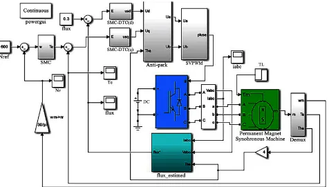
In this paper, the simulation model is built by matlab/simulink. The system in-cludes multiple subsystem modules such as flux linkage and torque estimation module, coordinate transformation module and speed adjustment module. The improved system model is shown in Figure 1.
The parameters of permanent magnet synchronous motor are set as follows: the stator winding resistance is Rs =1.2Ω, stator inductance Ld =Lq=0.0085 H,
rotor flux linkage ψ =f 0.175 Wb, moment of inertia J=0.0008 kg m⋅ 2, pole
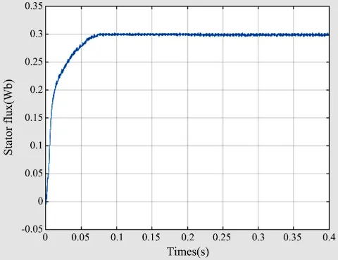
logarithm p = 4, the system friction coefficient B = 0. The system simulation pa-rameters are: given speed is ωm∗ =600 rad min , given flux linkage is
* 0.3 Wb
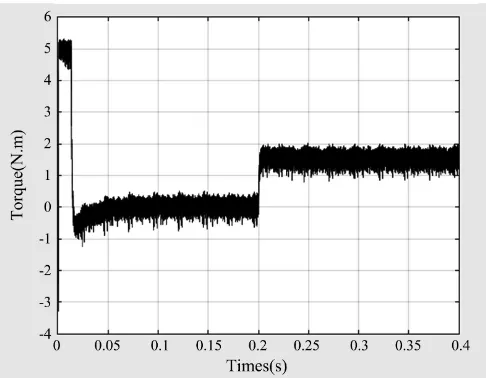
ψ = , load torque TL =1.5 N m⋅ is applied in 0.2 seconds. Simulation
[image:6.595.64.540.431.702.2]time is 0.4 s. The simulation results are shown in Figures 2-7.
DOI: 10.4236/oalib.1105758 7 Open Access Library Journal
[image:7.595.251.495.294.484.2]Figure 2. Traditional DTC motor speed curve.
Figure 3. Improve DTC motor speed curve.
[image:7.595.251.494.516.705.2]DOI: 10.4236/oalib.1105758 8 Open Access Library Journal
[image:8.595.253.493.295.485.2]Figure 5. Improve the electromagnetic torque curve of DTC motor.
Figure 6. Traditional DTC motor electromagnetic torque curve.
[image:8.595.253.493.519.704.2]DOI: 10.4236/oalib.1105758 9 Open Access Library Journal
It can be seen from Figures 2-7 that when the motor speed increases from 0 to 600 r/min, compared with Figure 2 and Figure 3, the conventional direct torque control has a large overshoot and the adjustment time is long, when it is within 0.2 s. When the load is applied, the rotational speed drops significantly and the steady-state performance is poor. In the improved direct torque control, the rotational speed has a small overshoot and the dynamic response is fast, and the rotational speed is substantially unchanged when the load is suddenly ap-plied. Comparing Figures 4-7, in the traditional direct torque control, the tor-que and flux linkage are large, and in the direct tortor-que control using the sliding mode variable structure control, the torque and flux pulsation are significantly reduced, so it can be seen The method adopted in this paper is effective, can im-prove the system speed regulation performance, reduce the ripple of the flux linkage and torque, and make the system have good dynamic response and an-ti-interference.
5. Conclusion
In this paper, based on the sliding mode theory, the flux linkage and torque con-troller and the sliding mode variable speed concon-troller are designed. Compared with traditional direct torque control simulation, the method used in this paper can effectively reduce the flux linkage and torque ripple. The system has strong anti-interference and robustness.
Conflicts of Interest
The authors declare no conflicts of interest regarding the publication of this pa-per.
References
[1] Luo, Z.W., Gu, A.Z. and Hong J.J. (2017) Research on Servo System of Permanent Magnet Synchronous Motor Based on Improved Sliding Mode Variable Structure Control. Machine Tool & Hydraulics, 19, 25-29.
[2] Jiang, C.F. (2008) Direct Torque Control System of Permanent Magnet Synchron-ous Motor Based on Double Fuzzy Control. Central South University, Changsha, 135-150.
[3] Jia, H.P. and He, Y.K. (2006) A Study on the Effect of Zero Vector in Direct Torque Control of Permanent Magnet Synchronous Motor. ElectricDrive, 4, 23-26. [4] Swierczynski, D. and Kazmierkowski, M.P. (2002) Direct Torque Control of
Per-manent Magnet Synchronous Motor (PMSM) Using Space Vector Modulation (DTC-SVM)-Simulation and Experimental Results. IEEE 2002 28th Annual Confe-rence of the Industrial Electronics Society, Sevilla, Spain, 5-8 November 2002, 751-755. https://doi.org/10.1109/IECON.2002.1187601
[5] Wu, H., Mu, G. and Cui, Y.F. (2008) Direct Torque Fuzzy Control Technology of Permanent Magnet Synchronous Motor. JournalofShenyangUniversityof Tech-nology, 30, 261-265.
DOI: 10.4236/oalib.1105758 10 Open Access Library Journal
TransactionsonIndustrialElectronics, 60, 4272-4280. https://doi.org/10.1109/TIE.2012.2213561
[7] Lai, Y.S., Wang, W.K. and Chen, Y.C. (2004) Novel Switching Techniques for Re-ducing the Speed Ripple of AC Drives with Direct Torque Control. IEEE Transac-tionsonIndustrialElectronics, 51, 768-775.
https://doi.org/10.1109/TIE.2004.831720
[8] Lu, G.Z., Hao, R.K. and Huang, J.H. (2018) Direct Torque Control of Permanent Magnet Synchronous Motor Based on Sliding Mode Variable Structure. Electronic MeasurementTechnology, (21)
[9] Ouyang, F. and Chen, L. (2018) New Approaching Sliding Mode Variable Structure Control of Permanent Magnet Synchronous Motor. Automationand Instrumenta-tion, 12, 21-25.
[10] Chen, F., Wang, M. and Liu, H.T. (2019) Research on PMSM DTC for Electric Ve-hicle Based on Improved Sliding Mode Variable Structure. MicroMotor, 1,79-82 [11] Wu, J., Dai, Y.H. and Tang, P. (2018) Research on Direct Torque Optimization