http://www.scirp.org/journal/jcc ISSN Online: 2327-5227 ISSN Print: 2327-5219
DOI: 10.4236/jcc.2019.77017 Jul. 23, 2019 206 Journal of Computer and Communications
AES Overhead Mitigation Using OpenMP
Hesham Alhumyani
Computer Engineering Department, Taif University, Taif, KSA
Abstract
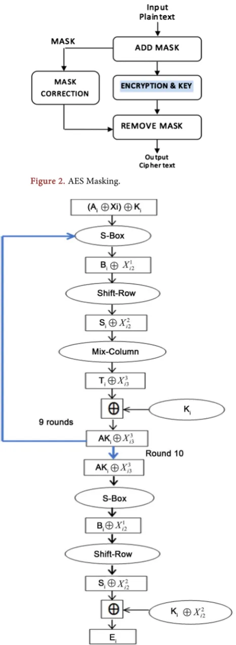
The Advanced Encryption Standard (AES) has been extensively used in many systems to provide security. However, many of the implementations are sus-ceptible to Side Channel Attacks (SCA). To address the susceptibility, several researchers have proposed a number of countermeasures. Masking scheme is one of the countermeasures that are commonly used to counteract such at-tacks. In this paper, we investigate the overhead of the countermeasure in terms of execution time of the first order-masking scheme for the AES “En-cryption part only”. To achieve that, we have implemented the sequential al-gorithm of the AES with single processor, and after that used OpenMP direc-tives to reduce the overhead of the countermeasure. Subsequently, the result of the sequential algorithm has been compared with its parallel implementa-tions using 2, 4, 6, and 8 processors. We show how parallel implementation of the AES offers better performance yet flexible enough for cryptographic algo-rithms. Compared to the sequential unmasked AES implementation, the best masking scheme for the first order using data parallelism shows a perfor-mance in terms of speed up around 5x when 8 threads are used.
Keywords
Advanced Encryption Standard, Encryptions, Parallelization, OpenMP
1. Introduction
AES (Advanced Encryption Standard), also referred to as Rijndael algorithm is classified as a symmetric key cryptography algorithm. In the year 1998, Rijndael algorithm was established by two Belgian scholars (John Daemen and Vincent Rijmen). This cipher was later on elected by the National Institute of Standards and Technology (NIST) [1] as the Advanced Encryption Standard (AES) to succeed the earlier Encryption Standard System. The AES standard possesses continuous blocks where each block contains 128 bits as well as 3 unalike key lengths. The first key length has a value of 128 bits while the second key length
How to cite this paper: Alhumyani, H. (2019) AES Overhead Mitigation Using OpenMP. Journal of Computer and Com-munications, 7, 206-218.
https://doi.org/10.4236/jcc.2019.77017
Received: June 19, 2019 Accepted: July 20, 2019 Published: July 23, 2019
Copyright © 2019 by author(s) and Scientific Research Publishing Inc. This work is licensed under the Creative Commons Attribution International License (CC BY 4.0).
DOI: 10.4236/jcc.2019.77017 207 Journal of Computer and Communications has a value of 192 bits, with the third and final key length having a value of 256 bits. For each key size, a number of encryption rounds will be pertained indivi-dually. Specifically, 10 encryption rounds are for the 128 bits, 12 encryption rounds are for 192 bits and 14 encryption rounds are for 192 bits. Further, throughout the encryption and decryption processes, a (4 * 4) changeable state array will be composed from the 16 bytes of data. During the encryption proce-dure, the state array is initialed with the original 16 bytes input data and will keep varying in each round until attaining the final encrypted data. On the other hand, in the decryption procedure, the state array is going to be initialed with the enciphered data and will be updated in each round until the initial data is fully recovered. The encryption of AES is accomplished in a fixed size block where the size of each block is 128 bits. The AES encryption calculations are computed through various repeated conversion rounds that construct the final output (cipher text) from the input plaintext. Each round has numerous processing stages, containing one that has a different encryption key. A set of reverse rounds is pragmatic to convert the encryption text back into the initial plaintext by the similar encryption key.
AES has been widely employed in numerous embedded devices with the ob-jective of enhancing security [2]. However, many employments of cryptographic are susceptible to Side Channel Analysis (SCA) for instance power-analysis [3] [4] and timing attacks [5] [6], which exploit both power usage and timing during cryptographic operations in order to access the key. To counteract this attack, masking techniques are considered to be suitable approach [7]. The notion of masking is to hide the real value with a corresponding random number. There-fore, the power usage caused by calculation of this value cannot be projected by the attacker. In this work, first, we are implementing the first-order masking scheme for the AES Encryption part so that we can investigate the overhead of the countermeasure. Second, the main contribution of this paper is to work spe-cifically on the Sub-byte function of the AES algorithm to reduce this overhead. With this software implementation, we are going to reduce the cost of masking in terms of execution time by using OpenMP library [8].
The rest of the paper is organized as follows. Section 2 discusses the detailed AES algorithm. Section 3 defines and discusses the side channel attacks. Section 4 shows the countermeasure of Side channel attacks through masking. Our pro-posed parallelism schemes are that algorithm is explained deeply in Section 5. The experimental results for a different number of threads are explained in Sec-tion 6. Finally, the conclusion is in SecSec-tion 7.
2. AES Algorithm
In this section the phases of AES Algorithm are explained as follows: 1) Key Expansion:
DOI: 10.4236/jcc.2019.77017 208 Journal of Computer and Communications round key block is needed by AES for every round in addition to one more extra round.
2) Initial Round:
At the beginning, an Add Round Key (pre-round transformation) will be ap-plied with each byte of the state been collected with a block of the round key employing bitwise XOR.
3) Rounds:
The number of the rounds is dependent on the specific length of each key while in every round, the following conversion will be followed:
a) Sub Bytes: this entails a non-linear replacement phase which involves every byte been replaced with an alternative one as per the lookup table.
b) Shift Rows: this is a switch phase where the last three rows of the state are moved sporadically with a specific number of stages. Shift Row changes the second row as 1 byte to the left, 2 bytes to the left for the third row and 3 bytes to the left for fourth row.
c) Mix Columns: this phase sees the 4 bytes of every column of the state been joined by an invertible linear change system. Indeed, the Mix Columns function precedes 4 bytes as input and outputs 4 bytes; with each input byte imitating all the four-output bytes. Collected with Shift Rows, diffusion in the encryption is delivered by the Mix Columns. Furthermore, in the operation, every column is multiplied and increased by a fixed matrix:
2 3 1 1
1 2 3 1
1 1 2 3
3 1 1 2
Matrix multiplication is comprised of addition and multiplying of the ac-cesses, and in this case, the multiplication process is described as follows: mul-tiplication by one implies no modification, mulmul-tiplication by two implies shifting to the left, whole multiplication by three implies shifting to the left and then presenting XOR with the preliminary unchanged assessment. Further, after shifting, a restricted XOR with 0x1B has to be accomplished if the shifted value is higher than 0xFF. The cases highlighted comprises of the distinct cases of the normal multiplication in Galois Field (GF) (28). Therefore, addition entails an
XOR operation. Generally, every column tends to be considered as a polynomial over GF (28) and is after that multiplied modulo x4 + 1 with an immobile
poly-nomial c(x) = 0x03 · x3 + x2 + x + 0x02. The resultant coefficients are
demon-strated in their hexadecimal equivalent of the binary demonstration of bit poly-nomials from GF (2) [x]. In case of the Mix Columns phase, it can also be ob-served as a multiplication by the illustrated specific Maximum Distance Separa-ble (MDS) matrix in the restricted field GF (28). This procedure is designated
more in the object Rijndael’s mix columns. d) Add Round Key:
ori-DOI: 10.4236/jcc.2019.77017 209 Journal of Computer and Communications ginated from the main key by the use of Rijndael’s key schedule with every sub-key been of similar size to the state sub-key. By connecting each byte of the state with the equivalent byte of the subkey, through the use of bitwise XOR, the subkey provides the support.
4) Final Round (no MixColumns) a) Sub-Bytes.
b) Shift Rows. c) Add Round Key.
3. Side Channel Attacks (SCA)
In this section the main idea of Side Channel Attacks (SCA) is explained:
SCA comprises of attacks which happen to be established on the Side Channel Information [3] [4] that is the information which can be recovered from the ci-pher device and is not the plaintext to be encrypted or the cici-pher text conse-quence emanating from the encryption procedure. Side channel exploration methods are of apprehension since the attacks can be displayed rapidly and at times can be applied using willingly accessible hardware whose costs vary from a couple of hundred dollars to a lot of thousands of dollars. The expanse of time necessary for the attack and scrutiny differs on the nature of attacks.
Simple Power Analysis (SPA) can be explained as a side-channel attack, that comprises visual analysis of graphs of the current that is used by a specific device over a given period of time. Differences in power usage occur as the device ex-ecutes dissimilar operations. For instance, distinctive directions accomplished by a microprocessor will have divergent power consumption outlines. Correspon-dingly, in a power trace from a smart card execution of an AES encryption, the ten rounds can be seen evidently as shown in Figure 1 [9].
[image:4.595.230.519.566.708.2]Timing attacks are constructed on calculating the duration it requires a unit to accomplish operations. This data can provide information related to the pass-word keys. For instance: by cautiously assessing the time interval needed to ac-complish private key operations, an intruder may find secure Diffie-Hellman exponents, factor Rivest Shamir Adleman (RSA) keys and get access to another cryptosystem. In case a unit is susceptible, the attack is obviously going to be
DOI: 10.4236/jcc.2019.77017 210 Journal of Computer and Communications simple and often necessitates only identified cipher text.
Comparably, squaring and multiplication operations in RSA accomplishments can frequently be illustrious, facilitating an attacker to process the password key. Even in cases when the magnitude of the variants in power usage is insignificant, average digital oscilloscopes could simply demonstrate the data-induced dispari-ties. In order to filter out high-frequency mechanisms, Frequency filters and av-eraging functions are regularly used.
Differential power analysis (DPA) comprises of a side-channel attack that holds statistically exploratory power usage capacities from a cryptosystem [10]. In this case, the attack operates bigotries differing power usage of microproces-sors or other hardware while exploit operations applies secret keys. DPA attacks possess signal processing and error correction controls that can contain confi-dences from capacities, that include a lot of noise to be considered applying ba-sic power evaluation. By making use of differential power analysis, an attacker can be in a position to attain password keys by investigating power usage capaci-ties from various cryptographic operations implemented by a susceptible smart card or other different devices. Different counter measures can be done to over-come those attacks. One of the measures entails inserting dummy operations randomly so that noise is made in the signal. Our countermeasure method against the side-channel attacks entails concealing the data at the point of calcu-lation, by either adding or multiplying the data with random values. All the phases in a round of AES are affine, with the exception of Galois field inversion sub step of the S-box (Sub Bytes) phase. As far as the other steps are concerned, the computation of the mask correction is linear hence the additive concealing is considered to be most convenient.
4. Masking in AES
In this section, we discuss the masking scheme which has been applied in this work on AES of 128-block size and 128 of key size (10 rounds). Random values “X” are generated at the beginning of the algorithm and XORed with plain text
“A”. Subsequently, the masked value (A⊕X) is XORed with the cipher key
“K”. AES operations will modify the random (mask) values during the AES
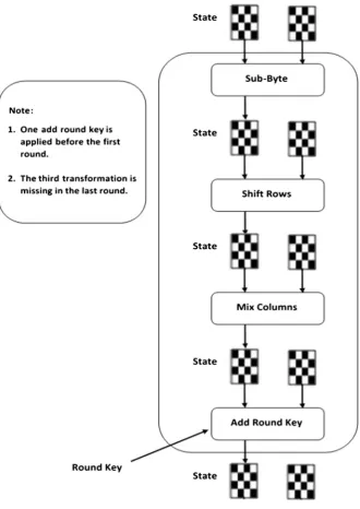
transformations. Hence, the mask values are corrected after each AES operation. In our implementation, during the execution of 10 rounds, the mask values are updated in Sub-Byte and Mix-Column steps to provide more security. Also, new mask values are generated again for a new plain text block. AddRoundKey is XORed with the plain text to form the input of each round. However, the Mix-Column and the mask values have to be removed from the last round (round 10) to form the cipher text as has been illustrated in Figure 2. Figure 3 illustrates the data flows in each round of AES with masking scheme. The fol-lowing is representing the rules expression of Figure 3:
DOI: 10.4236/jcc.2019.77017 211 Journal of Computer and Communications Figure 2. AES Masking.
DOI: 10.4236/jcc.2019.77017 212 Journal of Computer and Communications • X: Represents the mask value.
• K: Represents the Key.
• 1
2
i
X : Represents the linear of mask transformation (“X1”) after sub byte step
and simultaneously the mask values are updated second time with the new mask value (“Xi2”).
• 2
2
i
X : Represents the linear of mask transformation after Shift row step “X2”
but it is not updated.
• 3
3
i
X : Represents the linear of mask transformation after Mix-column “X3”
step and simultaneously the mask values are updated third time with the new mask value “Xi3”.
• Symbol “B”, “S”, “T” and “AK”: Demonstrates the output state after Sub-Byte, Shift Row, Mix-column and after AddRoundkey steps respectively. • E: Represents the cipher text.
S-Box implementation:
Here, we highlight the justification in why we chose the Sub-Byte function to be the perfect candidate for parallelism. The Sub-Byte step in the basic AES al-gorithm replaces each byte in the state matrix from its corresponding look-up value. However, the first-ordered masking includes an additional 16 bytes for the random values as shown in Figure 4.
AES S-box is described by a multiplicative inverse x − 1 and an affine trans-formation. In order to get the inverse, each byte has to be multiplied by itself 254 times such that x254∙x = 1 in the Galois Field and hence x − 1∙x = 1. Once inverse has been obtained, affine conversion is applied by multiplying multiplicative in-verse value with a fixed matrix and then adding it with 0 × 63 as follows:
7 1 1 1 1 1 0 0 0 7 0
6 0 1 1 1 1 1 0 0 6 1
5 0 0 1 1 1 1 1 0 5 1
4 0 0 0 1 1 1 1 1 4 0
3 1 0 0 0 1 1 1 1 3 0
2 1 1 0 0 0 1 1 1 2 0
1 1 1 1 0 0 0 1 1 1 1
0 1 1 1 1 0 0 0 1 0 1
b a b a b a b a b a b a b a b a = × ⊕
The main difficult part while designing a masking is Sub-Byte step because it is nonlinear transformation. On the other hand, the part of multiplicative in-verse is the only part that has to be modified. Thus, we used the proposed me-thod (a secure inverse algorithm) to generate the multiplicative inverse for a given number in GF (s8). It is important to note that during the calculation of the algorithm in this operation, the mask values are updated. Therefore, there are lots of computations in the Sub-Byte making it a good candidate to be paral-lelized.
5. Parallelism
DOI: 10.4236/jcc.2019.77017 213 Journal of Computer and Communications Figure 4. An additional matrix for the mask.
this work. The first method is using dividing data to run independently, and the second method is to apply the parallelism specifically in the Sub-Byte function. The detailed explanation is presented below:
5.1. Data Parallelism
DOI: 10.4236/jcc.2019.77017 214 Journal of Computer and Communications encryption algorithm entails the Electronic Code Book (ECB) mode. The com-plete plain text is divided into blocks of a certain length which can be processed individually. Every block of plaintext is encoded with a similar key as a unit and transformed into a cipher text block. Each thread takes 16 bytes at a time and executes the AES encryption independently. When the threads finish the job, there is a barrier being used to make sure that the writing to the cipher text has to be ordered according to the order of the plain text.
5.2. Task Parallelism
Here everything is executed sequentially except the Sub-Byte step. As mentioned above, the Sub-Byte stage takes more time to generate the Sub-Byte value. In the Sub-Byte operation, instead of a single thread doing the multiplicative inverse and the affine transformation alone for each byte in the (4 * 4) state matrix; we assign different threads to different bytes. Since each byte can be calculated in-dependently with no dependencies, parallel paradigm can be implemented in this stage. Since we have a two-dimensional array, we have used nested for-loop in order to reach each byte. Thus, we used the proper method that parallelizes the nested for-loop in OpenMP and increases the performance.
6. Experiment Results
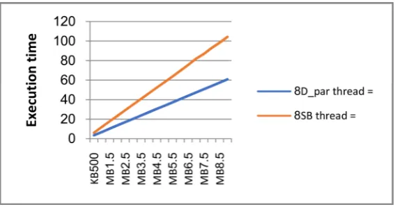
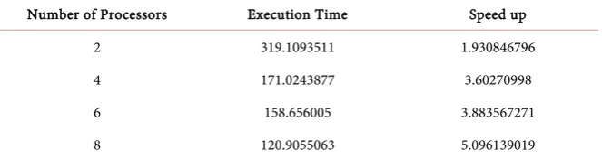
The AES algorithm has been efficaciously parallelized using OpenMP API direc-tives and compiled in GCC Linux. The specifications of the system used are: In-tel Core i7-3770 that has 3.40 GHz CPU, an 8 GB RAM and a 6 MB cache size. We implemented the sequential part of the code and then worked on the paralle-lization part. We carried out the experiments on different file sizes using differ-ent threads numbers while a number of threads have been used to execute the AES algorithm on different file sizes that vary from 500 KB to 9 MB and have a scale of 500 KB. Figure 5 and Figure 6 illustrates the execution time of data and Sub-Byte parallelism respectively using 2, 4, 6 and 8 threads on different data size. As it can be clearly seen in both figures, the running time increases linearly as the data increases. In Figure 5, the execution time is reduced from around 325 seconds to 60 seconds when using 8 threads with 9MB of data, whereas the best enhancement, in terms of the execution time in Sub-Byte parallelism (Task parallelism) is reduced to 100 seconds as shown in Figure 6.
Figure 7 illustrates the differences between data and Sub-Byte parallelism us-ing 8 threads. Both methods have given us an enhancement in the speed up. The figure points out that the data parallelism gives better enhancement than the Sub-Byte. It is well known that splitting the data will lead to no dependency in the AES encryption and hence, it would be better. The enhancement of the task parallelism shows the overhead that the Sub-Byte operation makes. Thus, para-lyzing this step would lead to an enhancement in the performance.
DOI: 10.4236/jcc.2019.77017 215 Journal of Computer and Communications Figure 5. Data parallelization using 2, 4, 6, and 8 threads.
Figure 6. Sub-Byte parallelization using 2, 4, 6, and 8 threads.
Figure 7. Data vs Sub-Byte parallelization using 8 threads.
[image:10.595.232.516.458.607.2]DOI: 10.4236/jcc.2019.77017 216 Journal of Computer and Communications Figure 8. Data parallelization speed up.
Figure 9. Sub-byte parallelization speed up.
Table 1. Data parallelization speed up using 2, 4, 6, and 8 threads.
Number of Processors Execution Time Speed up
2 388.6366678 1.585417227
4 247.4803907 2.489697332
6 249.1675771 2.472838865
8 208.2105133 2.959270685
Table 2. Sub-Byte parallelization speed up using 2, 4, 6, and 8 threads.
Number of Processors Execution Time Speed up
2 319.1093511 1.930846796
4 171.0243877 3.60270998
6 158.656005 3.883567271
8 120.9055063 5.096139019
[image:11.595.207.540.441.531.2] [image:11.595.209.541.564.652.2]DOI: 10.4236/jcc.2019.77017 217 Journal of Computer and Communications As can depict from Figure 8 and Figure 9, when the number of threads in-creases the speed up inin-creases even though when it reaches a certain point, there is only a slight increase. Therefore, increasing the number of processors after that point might not enhance the performance and due to that, there is no need for more processors. The main reason behind this steady state or slight increase is because the synchronization process between the used threads. As a result, an overhead arises and affect the performance.
7. Conclusion
The paper has explained in detail the parallelization of the AES algorithm. The AES input is handling 128 bits (one block) at a time. Each block goes through several operations such as Sub-Byte, Shift-Row, Mix-Column and each operation depends on the previous one. The AES algorithm has been parallelized using two methods namely Data and Sub-Byte parallelization. Each block (128-bit) from the plain text that is going to be encrypted is independent. Thus, the first phase is to apply the (single instruction multiple data) method (SIMD) since each block is independent from one another. Since we are using masking technique, we observe that the sub-Byte operation dominated the cost overhead. Thus, we decided to parallelize the Sub-Byte operation because it requires multiplicative inverse and affine transformation for each given byte and that consumes more time in computations. On the other hand, OpenMP directives have been em-ployed to parallelize the code and address the problem of the overhead caused by masking with up to 8 threads that have been used to run multiple experi-ments. Finally, our work mainly focused more in the Sub-Byte function and we had limited number of threads. Therefore, in the future work, we consider us-ing Field-Programmable Gate Array (FPGA) to utilize the hardware through performing many computations which we are expecting a better enhancement in both speed and security aspects.
Conflicts of Interest
The author declares no conflicts of interest regarding the publication of this paper.
References
[1] Daemen, J. and Rijmen, V. (2013) The Design of Rijndael: AES-the Advanced En-cryption Standard. Springer Science & Business Media, New York.
[2] Selvaraju, N. and Sekar, G. (2010). A Method to Improve the Security Level of ATM Banking Systems Using AES Algorithm. International Journal of Computer Appli-cations, 3, 5-9.
[3] Brier, E., Clavier, C. and Olivier, F. (2004) Correlation Power Analysis with a Lea-kage Model. In: Joye, M. and Quisquater, J.J., Eds., Cryptographic Hardware and
Embedded Systems-CHES 2004. Lecture Notes in Computer Science, Springer,
Ber-lin, Heidelberg. https://doi.org/10.1007/978-3-540-28632-5_2
DOI: 10.4236/jcc.2019.77017 218 Journal of Computer and Communications
Secrets of Smart Cards. Springer Science & Business Media, New York.
[5] Kocher P.C. (1996) Timing Attacks on Implementations of Diffie-Hellman, RSA, DSS, and Other Systems. In: Koblitz, N., Eds., Advances in CryptologyCRYPTO
1996. Lecture Notes in Computer Science, Springer, Berlin, Heidelberg, 104-113.
https://doi.org/10.1007/3-540-68697-5_9
[6] Rebeiro, C., Mukhopadhyay, D. and Bhattacharya, S. (2014) Timing Channels in Cryptography: A Micro Architectural Perspective. Springer Publishing Company, Cham.
[7] Coron, J.-S. (2014) Higher Order Masking of Look-Up Tables. In: Nguyen, P.Q. and Oswald, E., Eds., EUROCRYPT 2014. Lecture Notes in Computer Science, Springer, Heidelberg, 441-458. https://doi.org/10.1007/978-3-642-55220-5_25
[8] http://www.openmp.org/
[9] Kocher, P., Jaffe, J. and Jun, B. (1999) Differential Power Analysis. In: Wiener, M., Eds., Advances in Cryptology. CRYPTO 1999. Lecture Notes in Computer Science, Springer, Berlin, Heidelberg, 388-397. https://doi.org/10.1007/3-540-48405-1_25
[10] Kocher, P., Jaffe, J., Jun, B. and Rohatgi, P. (2011)Introduction to Differential Pow-er Analysis. Journal of Cryptographic Engineering, 1, 5-27.
![Figure 1. AES power tracing from [9].](https://thumb-us.123doks.com/thumbv2/123dok_us/9018854.398485/4.595.230.519.566.708/figure-aes-power-tracing-from.webp)