ISSN Online: 2153-0661 ISSN Print: 2153-0653
DOI: 10.4236/ica.2019.103005 May 29, 2019 79 Intelligent Control and Automation
Kinect-Based Motion Recognition Tracking
Robotic Arm Platform
Jinxiao Gao*, Yinan Chen, Fuhao Li
Jilin University Instrument Science and Engineering Institute, Changchun, China
Abstract
The development of artificial intelligence technology has promoted the rapid improvement of human-computer interaction. This system uses the Kinect visual image sensor to identify human bone data and complete the recogni-tion of the operator’s movements. Through the filtering process of real-time data by the host computer platform with computer software as the core, the algorithm is programmed to realize the conversion from data to control sig-nals. The system transmits the signal to the lower computer platform with Arduino as the core through the transmission mode of the serial communica-tion, thereby completing the control of the steering gear. In order to verify the feasibility of the theory, the team built a 4-DOF robotic arm control sys-tem and completed software development. It can display other functions such as the current bone angle and motion status in real time on the computer operation interface. The experimental data shows that the Kinect-based mo-tion recognimo-tion method can effectively complete the tracking of the expected motion and complete the grasping and transfer of the specified objects, which has extremely high operability.
Keywords
Kinect, Arduino, Bone Angle, Motion Tracking, Robotic Arm Platform
1. Introduction
WITH the vigorous development of artificial intelligence in recent years, hu-man-computer interaction has become a hot issue of concern. Motion recogni-tion has a wide range of applicarecogni-tions in people’s daily medical [1], education, entertainment and many other fields. In addition, motion analysis is one of the key technologies of industrial engineering. The related methods to realize this technology have been stuck in the manual stage, which is not only a large How to cite this paper: Gao, J.X., Chen,
Y.N. and Li, F.H. (2019) Kinect-Based Motion Recognition Tracking Robotic Arm Platform. Intelligent Control and Automa-tion, 10, 79-89
https://doi.org/10.4236/ica.2019.103005
Received: April 17, 2019 Accepted: May 26, 2019 Published: May 29, 2019
Copyright © 2019 by author(s) and Scientific Research Publishing Inc. This work is licensed under the Creative Commons Attribution International License (CC BY 4.0).
DOI: 10.4236/ica.2019.103005 80 Intelligent Control and Automation workload but also inefficient. Human posture and specific movements are a way for people to interact with surrounding information or creatures [2]. The re-search around motion recognition can be traced back to the 1980s in the world. Since then, the research on human motion recognition has gradually penetrated into various fields of research and development, and has been rapidly developed.
In 2013, Kumar, S.H.’s team explained a feature recognition based motion recognition method [3]. In 2016, Wenbing Zhao proposed two methods in the article: Machine learning recognition movement and rule-based direct compari-son method, but there is no specific experiment to elaborate [4]. In the article, Ning Wenjing proposed a model of exercise training by directly comparing data
[5]. And Frederick Matsen and other authors used Kinect to complete the data measurement and processing of the shoulder joints, making Kinect play an ef-fective role [6].
Motion recognition tracking refers to the positioning of certain characteristic motions of the human body, target detection, extraction, recognition and track-ing, and obtaining the state of human motion such as position, velocity and mo-tion trajectory, thereby completing processing and analysis, and obtaining a cer-tain amount of Valuable practical parameters to achieve automatic processing and analysis of human motion to complete the task of motion tracking, and strive to expand to apply to other aspects [7]. Simulation has always been one of the key directions of human ergonomics and robotic artificial intelligence re-search. At present, the large-scale simulation machinery used by people in pro-duction and propro-duction is costly and has not been put into use. This article will use Microsoft’s Kinect sensing and build a real-time motion tracking platform that can complete real-time motion information processing. The platform is based on a 4-DOF robotic arm. After experimental verification, the accuracy rate can reach 95.24%, and the delay can be reached 42.8 ms. The following sections will mainly introduce the structure and function of the system from the overall structure of the system platform, hardware introduction, software design and experimental data testing.
2. Overall Structure of the Proposed Controlling System
DOI: 10.4236/ica.2019.103005 81 Intelligent Control and Automation The software also adds real-time screenshots and recording functions to com-plete the background saving and processing of bone angles during any operation time. Figure 1 shows the overall structure of the system.
3. Control System Hardware Structure
3.1. Kinect V2.0
The camera can recognize the movement of the human body by means of infra-red rays, and it can emit infrainfra-red rays to stereoscopically position the entire room. The orientation of the object is judged based on the time the light is re-flected back, followed by the optical coding technique—The use of a laser to il-luminate an irregular object will randomly produce a highly random diffraction spot, so the intensity of the spot at any two locations is different [9]. Spots are rec-orded on a reference plane at intervals and accumulate to form a three-dimensional shape. By scanning the pixels point by point, the contours of the human body can be distinguished. Finally, the parts of the human body are marked with no color, and the joint nodes are easily and accurately found.
Main components and parameters:
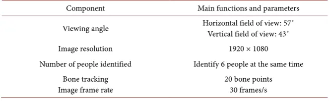
[image:3.595.245.502.418.577.2]The main parameters of Kinect V2.0 are shown in the table. Kinect mainly has RGB inductive cameras, deep vision sensors, which can detect and recognize certain viewing angles and multi-point array microphones for speech recogni-tion and output sound. Table 1 illustrates the main functions and parameters of Kinect.
Figure 1. Overall structure of the system.
Table 1. Main functions and parameters of Kinect.
Component Main functions and parameters
Viewing angle Horizontal field of view: 57˚ Vertical field of view: 43˚
Image resolution 1920 × 1080
Number of people identified Identify 6 people at the same time Bone tracking
Image frame rate
[image:3.595.208.540.624.726.2]DOI: 10.4236/ica.2019.103005 82 Intelligent Control and Automation 3.2. Steering Gear
In this system, the stability of the steering gear directly affects the stability of the system. The steering gear has a wide range of applications, simple control and more stability. It can be set as a basic output actuator. It simple control makes the lower position controller easy to connect with.
The system adopts the steering gear of model LDX218, and the control signal enters the internal modulation chip of the steering gear, and a certain DC bias voltage is obtained through signal processing. It compares the generated DC bias voltage with the potentiometer voltage (period 20 ms, width 1.5 ms), and obtains the voltage difference as the analog quantity of the output control signal. The magnitude of the voltage determines the speed of the motor, and positive and negative represent the steering of the motor. When the voltage difference is 0, the motor stop rotating. The PWM square wave is the control signal of the steering gear, and the transient characteristics of the duty cycle are used to change the rotational characteristics of the steering gear.
3.3. Lower Machine
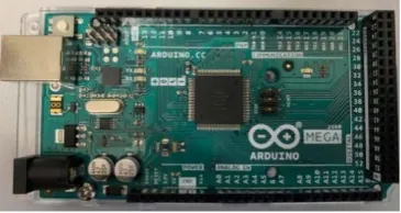
The system is intended to use the Arduino Mega 2560 as the core control mod-ule. It is an open source electronic prototyping platform with small size, fast processing speed and convenient operation. It can connect various sensors to sense the current state and get feedback or send control signals. Its development is based primarily on the Arduino IDE environment, which also increases its development efficiency. The system mainly uses the lower computer to process the serial port data sent by the computer, and then transmits the control signal to the steering gear through the control board to control the robot arm. Figure 2
is a practical picture of Arduino.
4. Control System Software Design
4.1. Flowchart
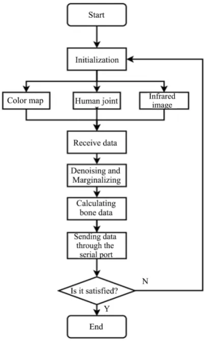
[image:4.595.283.466.612.709.2]The overall flow chart of the PC software is as shown in the figure below. After the start, the initialization object operation is needed to determine the tracking target, open the sensor, and start collecting the depth data and bone data using Kinect’s image acquisition function. After filtering, Display current image and data information in the software operation interface. Figure 3 is the software flow chart of the upper computer.
DOI: 10.4236/ica.2019.103005 83 Intelligent Control and Automation
Figure 3. Flow chart of computer software.
After calculating the steering angle of the steering gear required by the algo-rithm, the rotation control information is sent to the lower platform by serial communication, thereby controlling the movement of the steering gear, that is, the mechanical arm, until the desired position is stopped.
4.2. Software Interface and Function
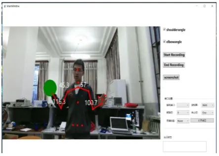
The operating system can complete real-time display of images, screen captures, video recording, storage of bone angle information, etc. Perceive real-time status and effective operation. Figure 4 shows the software operation interface.
4.3. Data Communication
DOI: 10.4236/ica.2019.103005 84 Intelligent Control and Automation
Figure 4. Software operation interface.
5. Algorithm Description
5.1. Bone Data Acquisition
Using the Kinect sensor’s visual perception technology, in principle, it automat-ically tracks the human bones within the target range before output, and displays a real-time dynamic map showing the position of the human bone. The coordi-nates acquired by Kinect’s depth data acquisition are depth image coordicoordi-nates, but in order to make the human motion vector calculation in the actual realistic three-dimensional coordinates, it is necessary to preprocess the data, complete the coordinate conversion, and thus calculate the subsequent bone angle. The operation provides the basis. The specific method is as follows:
(
)
(
)
(
)
10 2
10 2
11.48 tan 1.18
r i r
i r
r i
w w
x x z P
h h
y y z P
z Hz O
γ
= − − ×
= − −
= × + −
among them (x y zr, r, r), (x y xi, i, i) for realistic 3D coordinates and depth image coordinates, O = 3.7 cm, P = 0.004, H = 0.0003 for realistic 3D coordinates and depth image coordinates.
5.2. Feature Extraction
If the Kinect sensor is recognized without locking the target, since the position of the target human body and the human body may change at any time, interfe-rence may occur, so the target needs to be locked first. The algorithm of the sys-tem is based on the feature recognition of the target operator’s bones, and the depth coordinates are converted into three-dimensional real coordinates, there-by utilizing the nature of the space vector and the relative position between dif-ferent bones to calculate the inter-bones. The angle, so that the computer com-pletes the processing of the data returned by the Kinect sensor and sends out real-time control signals.
DOI: 10.4236/ica.2019.103005 85 Intelligent Control and Automation operates with only 4 bones of one of the identified bones.
Because Kinect has a fast refresh rate of 30 frames/s, it may cause the coordi-nates to change continuously during the same minute time period in the bone recognition process. Therefore, some means are needed to process the data col-lected in real time. This process is called “data filtering”. In order to reduce the negative stability of its calculation, we adopt the average method which is easier to implement. We continuously use a fixed set of N real-time values as a set of data once, arranged in group, the group leader is fixed to N unchanged, the new data at the next moment is stored in the end of the group, and the data at the head of the group is removed, and so on, so that different values at different times are obtained, and the N data in the obtained group are taken average val-ue. You can expect a more stable result.
n
k i k j
J m
y p y +
=
=
∑
1, 2, ,
k= +m m+ N−n
In the formula, pi is the weight coefficient, and n i 1
i m= p =
∑
, the system goes ton = 10, that is, every 10 sets of data is processed as a group, m = 0, n = 9, the first 10 data from the above formula cannot participate in the calculation, because it can measure 30 times per second, there will be 30 sets of data within 1 second, that is, y1−y20 are valid. Every 10 numbers take the arithmetic mean to get 2 data, and finally 2 data values are returned. By averaging the bones correspond-ing to the four degrees of freedom, actual three-dimensional coordinate values of the four groups returned within each second can be obtained.
After the filtered stable value is obtained, the angular feature calculation can be performed. First, the vector between the four bones is obtained from the ac-tual three-dimensional coordinates, and a total of three sets of vector values are obtained a b c, , . According to the correspondence, the shoulder angle is
,
a b
θ = . The elbow angle is β = b c , , using these actual vectors to map the angular features.
By a b
a b
θ= ⋅ ⋅
Got 1 1 2 2 3 3
1 2 3 1 2 3
2 2 2 2 2 2
i j i j i j
i j
i i i j j j
x x x x x x
x x x x x x
θ−
+ +
=
+ + + + +
Calculated 1 2 3
1 2 3
i i i i
j j j j
x x x x y x z x x x x y x z
= + +
= + +
DOI: 10.4236/ica.2019.103005 86 Intelligent Control and Automation large amount of real-time data must be filtered to improve system performance and reduce fault tolerance.
6. System Performance Test
6.1. Feasibility
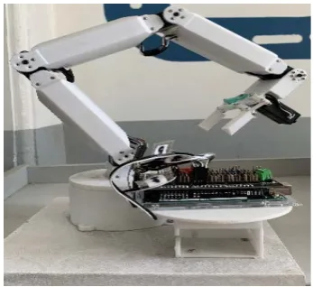
In order to verify the operability of the above theory, the team built a hardware robotic arm platform system. The robot arm uses the Arduino as the main controller, and completes the PWM square wave control of the steering gear. Before starting the startup, the actual serial connection is performed. Under dif-ferent background environments and light intensities, identify the same actions of the operators and complete the corresponding requirements. The method to be tested in this system is to grab and carry objects to a designated location to verify system stability and accuracy. Figure 5 is the actual built mechanical arm platform.
6.2. Recognition Rate
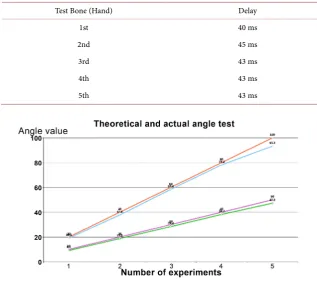
The Kinect was placed horizontally on a platform with a height of 70 cm from the ground. The tester was 150 cm away from the Kinect device, and the opera-tion was completed as required. The recording funcopera-tion of the developed oper-ating software was used to complete the recording. Figure 6 and Table 2 show the theoretical and actual values of the shoulder and elbow joints during the ac-tual test, as well as the size of the error.
After much verification, the average recognition rate reaches 95.24%, and the average error is 5.15%. It can be approximated that it can complete the recogni-tion and tracking of the target acrecogni-tion.
6.3. Real-Time Rate
[image:8.595.286.460.548.707.2]Under the same conditions, the hand is taken as an example to measure its delay time. Table 3 lists the test results of the delay, and you can see that the delay is relatively stable. Figure 7 shows the pictures in the actual test process.
DOI: 10.4236/ica.2019.103005 87 Intelligent Control and Automation
Table 2. Elbow and shoulder recognition error rate test.
Test Bone Shoulder Recognition Error Rate Elbow Recognition Error Rate
1 9.00% 4.50%
2 6.00% 5.50%
3 5.33% 2.27%
4 4.50% 2.25%
[image:9.595.208.526.222.504.2]5 5.40% 6.70%
Table 3. Elbow recognition rate test.
Test Bone (Hand) Delay
1st 40 ms
2nd 45 ms
3rd 43 ms
4th 43 ms
[image:9.595.265.485.545.707.2]5th 43 ms
Figure 6. Elbow and shoulder recognition test.
DOI: 10.4236/ica.2019.103005 88 Intelligent Control and Automation
7. Conclusions
Through the tracking simulation of the movement of the human body by the motion recognition system, it will replace the work of high-risk, high-difficult and difficult working environment in the future. In the aspect of transportation, the human motion recognition and tracking system can replace the daily atten-dance command of the traffic police. The traffic work avoids all kinds of acci-dents that occur during the work of the traffic police, so that the traffic police can remotely direct traffic in the distance, improve work efficiency and reduce the burden on the traffic police. In addition, medical and health, industrial pro-duction and many other areas of propro-duction and life have a certain use value. In summary, human motion recognition and tracking system have great research value.
The system uses the Kinect visual image sensor to collect the bone data of the human body, and transforms the data into a control command of the steering gear, thereby completing the recognition of the motion and mapping it to the constructed 4-DOF manipulator platform. Indirectly the function of hu-man-computer interaction realized.
Conflicts of Interest
The authors declare no conflicts of interest regarding the publication of this pa-per.
References
[1] Matsen, F., Lauder, A., Rector, K., Keeling, P. and Cherones, A.L. (2016) Measure-ment of Active Shoulder Motion Using the Kinect, a Commercially Available Infra-red Position Detection System. Journal of Shoulder and Elbow Surgery, 25, 216-223.
https://doi.org/10.1016/j.jse.2015.07.011
[2] Wang, P., Liu, H.Y., Wang, L.H. and Gao, R.X. (2018) Deep Learning-Based Human Motion Recognition for Predictive Context-Aware Human-Robot Collaboration.
CIRP Annals—Manufacturing Technology, 67, 17-20.
https://doi.org/10.1016/j.cirp.2018.04.066
[3] Kumar, S.H. and Sivaprakash, P. (2013) New Approach for Action Recognition Us-ing Motion Based Features.2013 IEEE Conference on Information &
Communica-tion Technologies, Thuckalay, Tamil Nadu, India, 11-12 April 2013, Article No.
13653652. https://doi.org/10.1109/CICT.2013.6558292
[4] Zhao, W.B. (2016) A Concise Tutorial on Human Motion Tracking and Recogni-tion with Microsoft Kinect. Science China (Information Sciences), 59, 237-241.
https://doi.org/10.1007/s11432-016-5604-y
[5] Ning, W.J. (2017) Research and Application of Sports Demonstration Teaching System Based on Kinect. Proceedings of the 6th International Conference on Social
Science, Education and Humanities Research (SSEHR 2017), Jinan, China, 18-19
October 2017, 570-574. https://doi.org/10.2991/ssehr-17.2018.126
[6] Xiang, C.K., Hsu, H.H., Hwang, W.Y. and Ma, J.H. (2014) Comparing Real-Time Human Motion Capture System Using Inertial Sensors with Microsoft Kinect.
DOI: 10.4236/ica.2019.103005 89 Intelligent Control and Automation Ulaanbaatar, Mongolia, 12-14 July 2014, 53-58.
https://doi.org/10.1109/U-MEDIA.2014.25
[7] Faria, D.R., Premebida, C. and Nunes, U. (2014) A Probabilistic Approach for Hu-man Everyday Activities Recognition Using Body Motion from RGB-D Images. The
23rd IEEE International Symposium on Robot and Human Interactive
Communi-cation,Edinburgh, UK, 25-29 August 2014, 732-737.
https://doi.org/10.1109/ROMAN.2014.6926340
[8] Tseng, Y.-W., Li, C.-M., Lee, A. and Wang, G.-C. (2013) Intelligent Robot Motion Control System Part I: System Overview and Image Recognition.2013 International
Symposium on Next-Generation Electronics, Kaohsiung, Taiwan,25-26 February
2013, 1-5.
[9] Vantigodi, S. and Radhakrishnan, V.B. (2014) Action Recognition from Motion Capture Data Using Meta-Cognitive RBF Network Classifier. Intelligent Sensors,
Sensor Networks and Information Processing (ISSNIP), 2014 IEEE Ninth
Interna-tional Conference, Singapore, 21-24 April 2014, 1-6.