T. Gao,1 E. Estrecho,1 G. Li,1 O. A. Egorov,2 X. Ma,3 K. Winkler,4 M. Kamp,4 C. Schneider,4 S. H¨ofling,4, 5 A. G. Truscott,1 and E. A. Ostrovskaya1 1
Research School of Physics and Engineering, The Australian National University, Canberra ACT 2601, Australia 2Institute of Condensed Matter Theory and Solid State Optics, Abbe Center of Photonics,
Friedrich-Schiller-Universit¨at Jena, Max-Wien-Platz 1, 07743 Jena, Germany 3
Department of Physics, Center for Optoelectronics and Photonics Paderborn (CeOPP), Universit¨at Paderborn, Warburger Strasse 100, 33098 Paderborn, Germany.
4Technische Physik, Wilhelm-Conrad-R¨ontgen-Research Center for Complex Material Systems, Universit¨at W¨urzburg, Am Hubland, D-97074 W¨urzburg, Germany
5
SUPA, School of Physics and Astronomy, University of St Andrews, St Andrews KY16 9SS, United Kingdom
We demonstrate, experimentally and theoretically, a Talbot effect for hybrid light-matter waves — exciton-polariton condensate formed in a semiconductor microcavity with embedded quantum wells. The characteristic ‘Talbot carpet’ is produced by loading the exciton-polariton condensate into a microstructured one-dimensional periodic array of mesa traps, which creates an array of sources for coherent polariton flow in the plane of the quantum wells. The spatial distribution of the Talbot fringes outside the mesas mimics the near-field diffraction of a monochromatic wave on a periodic amplitude and phase grating with the grating period comparable to the wavelength. Despite the lossy nature of the polariton system, the Talbot pattern persists for distances exceeding the size of the mesas by an order of magnitude. Thus, our experiment demonstrates efficient shaping of two-dimensional flow of coherent exciton-polaritons by a one-dimensional “flat lens”.
Introduction.—The Talbot effect is a manifestation of
near-field(Fresnel) diffraction of a coherent plane wave incident on a periodic grating, which results in a non-trivial 2D pattern of fringes often referred to as a ‘Talbot carpet’. According to the Huygens-Fresnel principle, it is interpreted as interference of coherent spherical waves originating from the apertures of the grating. Nearly two centuries after the discovery of the optical Talbot ef-fect [1], it continues to be re-discovered and re-examined in the context of matter and optical waves of various physical nature and spatial scales. Apart from the lin-ear and nonlinlin-ear optical waves [2–7], the Talbot effect has been observed with atoms [8–11], molecules [12], elec-trons [13], X-rays [14, 15], single photons [16], and surface plasmon-polaritons (SPPs) [17–20]. The visually stun-ning effect is not purely of aesthetic value. Talbot inter-ference has a deep connection with number theory and theory of quantum revivals [21, 22], and serves a range of practical purposes. Indeed, periodic self-imaging of the source resulting from the spatial Talbot effect [23] gives rise to grating-based imaging techniques [14, 15, 24]. Var-ious applications of temporal and spatial Talbot effects in metrology, data transmission, atomic lithography, and optical manipulation have also been suggested [7, 25–27].
[image:1.595.329.553.322.481.2]The common prerequisite for the observation of the spatial Talbot effect is a periodic arrangement of sources of coherent spherical waves that can propagate in the di-rection perpendicular to the didi-rection of the array. In optics, this is naturally achieved by diffraction of an in-cident light on an array of apertures [7]. However, this effect can also be reproduced by other means. For ex-ample, in SPP physics Talbot interference of waves from periodically arranged sources rather than diffraction of a
FIG. 1: Schematics of (a) an elliptical optical pump illumi-nating a 1D array of mesa traps in a microcavity and (b) po-lariton flows (arrows) responsible for the Talbot effect in (d). Real space images of the exciton-polariton emission (c) at low excitation power, below the condensation threshold and (d) at high excitation power, above the condensation threshold. The Talbot effect is visible in (d).
plane wave on a periodic grating has been observed [20].
semicon-ductor microcavity, the latter ensuring resonance with a long-lived photon mode. Periodic potentials for po-laritons can be formed by surface metal deposition on the semiconductor microcavity [34, 39, 40], acoustic wave modulation [36, 41], deep etching of micropillars [35, 38] or microstructuring of buried mesa traps [37, 42] (see [43] and references therein). These potentials act as a solid-state superlattice: when a microcavity is opti-cally pumped, the exciton-polaritons populate the energy bands of the resulting periodic potentials. Propagation of coherent polariton waves in the plane of a quantum well, away of the periodic array, has never been investi-gated in detail because it is difficult, if not impossible, to avoid trapping of polaritons in stationary (extended or localised) states of the 1D array [35, 36].
In this work, we employ an exciton-polariton conden-sate in a 1D buried mesa array of polariton traps [see schematics in Fig. 1(a,b)] to observe the Talbot interfer-ence patterns with coherent hybrid light-matter waves. The Talbot effect for exciton-polaritons is uniquely en-abled by the ability of exciton-polaritons to condense into a non-ground extended (Bloch) state of the 1D array [37, 42], as well as by the nature of the mesa traps, which are embedded into the microcavity [42] rather than form-ing free-standform-ing pillars on the substrate [35]. When the Bloch mode is characterized by a periodic distribution of polariton density maxima located in thebarriersbetween mesa traps, the barrier regions act as sources of polari-ton waves, which are free to propagate in the plane of the quantum well [see Fig. 1(b)]. The periodic array of such sources creates a Talbot carpet shown in Fig. 1(d). Moreover, we demonstrate that this system mimics both amplitude and phase gratings for the light-matter waves.
Experiment.— The experiment was performed using 1D mesa arrays microstructured in an AlAs/AlGaAs mi-crocavity with GaAs quantum wells, as described in [42]. Mesas of 3.5 µm diameter are separated centre-to-centre by the distance of 5.5 µm, with the effective polariton potential depth of∼5 meV for each mesa. The exciton-polariton condensate is formed spontaneously by pump-ing the microcavity with a cw laser injectpump-ing free car-riers well above the polariton energy. The pump beam has a FWHM dimension of 2.5×36 µm, which illumi-nates approximately 6 mesas, as shown in Fig. 1(c). Real and reciprocal space imaging of the cavity photolumi-nescence resulting from the polariton decay is used to analyse the spatial density distribution and dispersion of exciton-polaritons.
In the regime of low excitation powers, the dispersion (energy vs. in-plane momentum) of exciton-polaritons created outside and in the mesa array are remarkably different. Outside the mesa array, the parabolic disper-sionE(k) near the in-plane momentumk= 0 is typical of the lower polariton dispersion branch in a planar micro-cavity, as seen in the Supplemental Material (SM) [44]. In contrast, the emission from polaritons located in mesa
FIG. 2: (a,b) Dispersion measurement of polariton emission from the mesa traps (a) below and (b) above condensation threshold. Both localised and extended energy states are seen in (a). Condensation in two gap states in the first (G1) and the third (G3) spectral gaps are visible in (b). Dashed yellow lines correspond to±kB/2 and mark the first Brillouin zone of
the array. The solid lines in (a) show the first four extended Bloch bands calculated from Eq. (1). (c,d) Energy filtered reciprocal space image of the condensate emission from the G3 state (c) measured in the experiment, and (d) calculated theoretically from the field distributionfT(r) (see text).
traps reveals the band-gap energy structure [45] imposed by the periodicity of the trapping potential in the lateral (x) direction [Fig. 2(a)], as described in [37, 42]. Both the discrete energy states in the individual mesas and the characteristic band-gap spectrum of extended Bloch states can be seen in Fig. 2(a). The lowest band of Bloch states is formed above the excited energy state in the in-dividual mesas, similarly to the spectra of the deep pho-tonic wires in organic microcavities [46, 47]. The gaps be-tween the energy bands become progressively narrower, as can be seen from the spectrum in Fig. 2(a).
[image:2.595.321.561.52.355.2]enve-lope. In particular, the highly populated steady state G3 forms in the very narrow third energy gap of the linear spectrum in Fig. 2(a). Its density and phase distributions are inherited from the stationary Bloch state at the top of the third spectral band. Unlike propagating polariton waves, the steady states trapped in the array are nearly monochromatic.
The reciprocal (k) space image of the emission inten-sity also undergoes dramatic changes above the exciton-polariton condensation threshold. At the low power, the
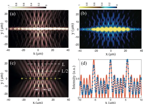
k-space image exhibits a ring-shape distribution due to the flow of the untrapped polaritons in all directions. Once the pump power exceeds the condensation thresh-old, polaritons condense predominantly in the G3 mode determined by the extended Bloch state of the mesa ar-ray. This state is characterised by two peaks at the edges of the third Brillouin zone kx = ±2.85µm−1 visible in Fig. 2(b) and the corresponding maxima in thek-space emission pattern Fig. 2(c). Moreover, Fig. 2(c) demon-strates discrete distribution of the polariton emission in-tensity in the k-space which suggests additional period-icity in the transverse (y) direction. This is the direct consequence of the Talbot effect, which is revealed in the spatial distribution of the polariton density.
In the G1 state, the majority of the polariton density is contained within the individual mesas, as seen in SM [44]. In contrast, the real space density distribution of the G3 state along the y = 0 line shown in Figs 3(a,d) displays larger polariton density in the potential barrier regions between the individual mesas. Polaritons in the barrier regions are free to propagate in the plane of the quantum well, thus generating coherent flow of polari-tons in the transverse direction. Real space image of the polariton flow outside the mesa array [Figs 3(a)] shows the interference structure consistent with the linear Tal-bot effect, with the spatial periodicity Tal-both in the lateral and transverse directions.
With the growing pumping power above the condensa-tion threshold, the contrast of the Talbot fringes becomes enhanced, as discussed in SM [44].
Theory.—The full dynamics of exciton-polariton con-densation in the one-dimensional mesa array for mod-erate pump powers above threshold can be reliably re-produced by the two-dimensional mean-field dynamical model taking into account energy relaxation due to quan-tum and thermal fluctuations in the system [49]. The detailed description of the model, which describes tran-sitions between different energy states occupied by the condensate in the mesa traps can be found in [37] and is reproduced in SM [44]. It consists of the open-dissipative Gross-Pitaevskii equation for the condensate wavefunc-tion incorporating stochastic fluctuawavefunc-tions and coupled to the rate equation for the excitonic reservoir created by the off-resonant cw pump [37, 49]. Numerical modelling with the parameters corresponding to our experiment re-produces condensation into a non-ground steady state
state with the real space density distribution shown in Fig. 3(b). It reveals the Talbot pattern in qualitative agreement with the experiment. In what follows, we present a simple, intuitive theory of this effect based on its analogy with the linear near-field diffraction.
In the low density regime, i.e., for excitation powers below the condensation threshold, the exciton-polaritons occupy the band-gap ladder of single-particle energy states in a periodic potential (see, e.g., [42] for details of the potential characterisation). The energy band struc-ture En(k), where n is the band index, can be calcu-lated directly by solving the stationary single-particle Schr¨odinger equation for the macroscopic wavefunction of the polariton condensateψ(x, y) in a periodic in-plane potential. Due to the 1D nature of the lateral periodicity, a dimensionality reduction can be performed, and eigen-values approximated by the spectrum of the factorised eigenstates ψ(x, y) = χ(y)φk(x) exp(−ikx), where χ(y) is a transverse mode of an individual mesa trap, and
φk(x) =φk(x+a) are the extended polariton Bloch states in aneffective1D potentialV(x) =V(x+a) with the in-plane momentumk≡kx. The 1D Bloch states obey the following equation:
~2 2mp
(k−i∇x) 2
+V(x)
φn,k(x) =En(k)φn,k(x). (1)
Heremp≈4.45×10⁻⁵me is the effective polariton mass in the planar region, and me is the free electron mass. We approximate the 1D periodic potential created by the mesas by the anharmonic analytical functionV(x) =
V0[F(x)−1], where:
F(x) = (1 +s)
2[1 + cos(k Bx)] 2 [1 +s2+ 2scos(k
Bx)]
,
andkB= 2π/ais the size of the Brillouin zone of the pe-riodic potential. The shapes of the potential for varying degrees of anharmonicity are described in [50].
The band-gap spectrum En(kx) calculated using Eq. (1) for the anharmonicity parameter s =−0.2 and the potential depthV0 = 5.2 meV, assuming the trans-verse ground state of the mesa χ(y) = χ0(y), demon-strates good agreement with the experimentally mea-sured spectrum, as seen in Fig. 2(a). We note, however, that the multitude of populated energy bands visible in Fig. 2(a) includes extended states formed by hybridis-ation of the higher-order two-dimensional modes of the individual mesa traps. One such band, weakly populated by low-density polaritons, is seen in Fig. 2(b) below the state G1 [44].
|φB(x)| are located in the local maxima of V(x) which correspond to the barrier regions of the mesa array. This Bloch state belongs to the top edge of the third energy band (n= 3) and therefore is a ’π-state’ with astaggered phase, i.e. its adjacent density peaks haveπphase differ-ence. This phase difference is inherited by the transverse flow of polaritons, which in turn leads to some charac-teristic features in the Talbot pattern. Conversely, from theintensityof the polariton emission in the Talbot pat-tern one can reliably infer the phase distribution of the condensate wavefunctionφB(x) in the mesa array.
The Talbot pattern can be reproduced by applying the linear Huygens-Fresnel principle to the polariton flow, thus assuming that polariton waves propagating away from the mesa array are of sufficiently low par-ticle density, so that the nonlinearity can be ignored. As indicated by the lateral period of the Talbot pat-tern, only the highest peaks of|φB(x)|2 act as sources of the coherent polariton flow. According to the Huygens-Fresnel principle, the condensate in the barrier regions can be represented by an array of point sources of de-caying radial waves whose field is given by [49]: fm ∼ (1/√r) exp[i(kprm+θm)−κrm], whererm=
p
|r−rm|2 is the relative distance between a point on the plane,r, and the position of the m-th source,rm, kp = 2π/λp is the polariton wavevector,κ=γmp/(2~kp) is determined by the polariton decay rateγ, andθmis the initial phase inherited fromφB(x). The total field of the Talbot car-pet is given by the linear superposition of waves from all sources: fT(r) =Pmfm, which, in our case, are located on the liney= 0.
Figure 3(c) shows the Talbot pattern reproduced by the linear theory assuming the polariton wavelength
λp = 2.6 µm and the polariton lifetime γ−1 ∼ 10 ps. The real space image is in excellent agreement with the experimental pattern Fig. 3(a). The dark lines located between bright lobes result from destructive interference between the adjacent sources due to the relativeπphase difference. Away from the x axis, the pattern distorts and eventually vanishes because of the finite number of sources and polariton decay. Nevertheless, the pattern persists for distances sufficient to re-image the source twice. Finally, the calculated Fourier transform of the Talbot pattern fT(r) matches the experimental k-space signature very well [cf. Figs. 2(c) and 2(d)]. The discrep-ancies between the calculated and experimental images stem from the theoretical assumption of distributed point sources located ony= 0, whereas in practice each source has a finite transverse extent.
The Talbot length is defined as the transverse distance at which the phase shift of all plane wave sources is equal to 2πN, whereNis an integer. At this distance, the orig-inal density distribution aty= 0 is revived. Remarkably, in our case the Talbot pattern demonstrates the complete revival at half the Talbot length L/2 [see Figs. 3(a,c)]. This is because the array of coherent polariton sources
FIG. 3: (a) Experimental spatial distribution of the Bloch mode intensity and the Talbot pattern [energy filtered at the G3 position in Fig. 2(b)]. (b,c) Talbot pattern calculated (b) numerically using the full nonlinear 2D mean-field model and (c) theoretically using the Huygens-Fresnel superposition. The ”+” and ”-” signs in (c) indicate relative π phase dif-ference between the adjacent sources of the polariton flow located between the mesas (black circles), andL marks the Talbot length; (d) Comparison between|φB(x)|2 calculated
using Eq. (1) (solid line) and the experimental real-space pro-file (circles) taken along the liney= 0 in (a).
created by the Bloch state mimics both amplitude and
phase gratings. At the transverse distance L/2, the phase of each source acquires aπshift, thus reproducing the staggered phase structure and the polariton density (emission intensity) pattern of the origin. The Talbot length determined from the transverse period of the pat-tern in the experimental real-space image isL≈20µm. The wavelength of the coherent polariton wave is compa-rable to the period of the mesa array (a= 5.5µm), and can be calculated using the non-paraxial correction to the
Rayleigh formula [20, 23]: L = λp[1− q
1−λ2 p/a2]−
1,
which yieldsλp ≈2.8 µm. This value agrees well both with that assumed in our theoretical calculations above, and with the de Broglie wavelength of the transversely free polaritons with the energyEp= 5.81 meV [state G3 in Fig. 2(b)]: λdB=h/
p
2mpEp= 2.4µm.
Finally, we note that the Talbot interference of exciton-polaritons is an ubiquitous effect. However, not every higher-order exciton-polariton mode responsible for leak-ing into the planar regions and generatleak-ing Talbot pat-terns may be captured by our simple 1D theory, as dis-cussed in SM [44].
[image:4.595.319.559.49.223.2]mesas. Polaritons at these locations are free to prop-agate transversely to the mesa array and therefore the barrier regions act as a periodic array of sources of co-herent polariton waves. Due to the nontrivial phase of the non-ground state in the array, these sources mimic both amplitude and phase gratings for the light-matter waves, which links our observations to the Lohmann ef-fect [51]. Moreover, the period of the grating is compara-bleto the wavelength of the coherent light-matter waves, which provides opportunity for exploring non-paraxial ef-fects on the microscale. Numerical calculations exploit-ing a mean-field nonlinear model of polariton conden-sation, as well as the linear Huygens-Fresnel diffraction theory, allow us to reproduce the spatial distribution and spectral signatures of the Talbot effect.
Our results represent the first, to the best of our knowl-edge, observation of the Talbot effect in a many-body quantum system of hybrid light-matter nature. This re-search opens the avenue for using the current advanced nanofabrication techniques to engineer flow patterns of exciton-polaritons in the plane of the quantum wells embedded in the microcavity. In particular, lensing, beam splitting, and phase-dependent shaping of polari-ton flows enabled by the Talbot interference could be re-alised by engineering the density and phase distributions of exciton-polaritons in 1D arrays (see [44] for details). In this respect, our observation can be linked to the 1D
flat lenses demonstrated for surface plasmon-polaritons [18, 19, 52], and, more generally, to emission-shaping optical metasurfaces [53, 54]. Further opportunities for shaping the polariton flow may be explored by utilising non-Hermitian optically-induced potentials [55] or spin polarization effects [56] in combination with polaritonic flat lenses. The resulting control over in-plane polari-ton propagation could aid the development of integrated polaritonic devices.
Acknowledgements This work was supported by the Australian Research Council and the state of Bavaria. O.A.E. acknowledges financial support by the Deutsche Forschungsgemeinschaft (DFG project EG344/2-1). As-sistance in the semiconductor sample fabrication by M. Emmerling, A. Schade and J. Gessler is gratefully ac-knowledged.
[1] H. F. Talbot, “Facts relating to optical science, No. IV,” Philos. Mag.9, 401 (1836).
[2] R. Iwanow, D. A. May-Arrioja, D. N. Christodoulides, G. I. Stegeman, Y. Min, and W. Sohler, “Discrete Talbot Effect in Waveguide Arrays”, Phys. Rev. Lett.95, 053902 (2005).
[3] Y. Zhang, J. Wen, S. Zhu, and M. Xiao, “Nonlinear Tal-bot effect”, Phys. Rev. Lett.104, 183901 (2010). [4] H. Ramezani, D. N. Christodoulides, V. Kovanis, I.
Vitebskiy, and T. Kottos, “PT-Symmetric Talbot
Ef-fects”, Phys. Rev. Lett.109, 033902 (2012).
[5] J. Aza˜na and H. G. de Chatellus, “Angular Talbot ef-fect”, Phys. Rev. Lett.112, 213902 (2014).
[6] Y. Lumer, L. Drori, Y. Hazan, and M. Segev, “Acceler-ating Self-Imaging: The Airy-Talbot Effect”, Phys. Rev. Lett.115, 013901 (2015);
[7] J. Wen,Y. Zhang, and M. Xiao, “The Talbot effect: re-cent advances in classical optics, nonlinear optics, and quantum optics”, Adv. Opt. and Phot.5, 83 (2013). [8] J. F. Clauser and Sh. Li, “Talbot-von Lau atom
inter-ferometry with cold slow potassium”, Phys. Rev. A49, R2213 (1994).
[9] M. S. Chapman, Ch. R. Ekstrom, T. D. Hammond, J. Schmiedmayer, B. E. Tannian, S. Wehinger, and D. E. Pritchard, “Near-field imaging of atom diffraction grat-ings: The atomic Talbot effect”, Phys. Rev. A51, R14 (1995).
[10] S. Nowak, Ch. Kurtsiefer, T. Pfau, C. David, “High-order Talbot fringes for atomic matter waves”, Opt. Lett.22, 1430 (1997).
[11] L. Deng, E. W. Hagley, J. Denschlag, J. E. Simsarian, M. Edwards, C. W. Clark, and K. Helmerson, “Temporal, Matter-Wave-Dispersion Talbot Effect”, Phys. Rev. Lett.
83, 5407 (1999).
[12] S. Gerlich, S. Eibenberger, M. Tomandl, S. Nimm-richter, K. Hornberger, P. Fagan, J. Txen, M. Mayor, and M. Arndt, “Quantum interference of large organic molecules”, Nat. Comm.,2, 263 (2011).
[13] B. J. McMorran and A. D. Cronin, “An electron Talbot interferometer”, New J. Phys.11, 033021 (2009). [14] C. David, B. N¨ohammer, H. H. Solak, E. Ziegler,
“Dif-ferential x-ray phase contrast imaging using a shearing interferometer”. Appl. Phys. Lett.81, 3287 (2002). [15] A. Momose, Sh. Kawamoto, I. Koyama, Y. Hamaishi, K.
Takai, and Y. Suzuki, “Demonstration of X-Ray Talbot Interferometry”, Japan. J. Appl. Phys.42, L866 (2003). [16] X.-B. Song, H. B. Wang, J. Xiong, K. Wang, X. Zhang, K.-H. Luo, and L.-A. Wu, “Experimental Observation of Quantum Talbot Effects”, Phys. Rev. Lett.107, 033902 (2011).
[17] M. R. Dennis, N. I. Zheludev, and F. J. Garc´ıa de Abajo, “The plasmon Talbot effect”, Opt. Exp.15, 9692 (2007). [18] F. M. Huang, Y. Chen, N. I. Zheludev, and F. J. Garc´ıa de Abajo, “Focusing of light by a nanohole array”, Appl. Phys. Lett.90, 091119 (2007).
[19] W. Zhang, Ch. Zhao, J. Wang, and J. Zhang, “An ex-perimental study of the plasmonic Talbot effect”, Opt. Express1719757 (2009).
[20] D. van Oosten, M. Spasenovi´c, and L. Kuipers, “Nanohole Chains for Directional and Localized Surface Plasmon Excitation”, Nano Lett.10, 286 (2010). [21] M. V. Berry and S. Klein, “Integer, fractional and fractal
Talbot effects”, J. Mod. Opt,43, 2139 (1996).
[22] M. V. Berry, I. Marzoli, and W. P. Schleich, “Quantum carpets, carpets of light”, Phys. World1439 (2001). [23] Lord Rayleigh, “On copying diffraction gratings, and
some phenomena connected therewith” Phil. Magn. 11
196 (1881).
[24] F. Pfeiffer, T. Weitkamp, O. Bunk, and C. David, “Phase retrieval and differential phase-contrast imaging with low-brilliance X-ray sources”, Nat. Phys.2, 258 (2006). [25] D. Bigourd, B. Chatel, W. P. Schleich, and B. Girard,
Ultrashort Pulses”, Phys. Rev. Lett.100, 030202 (2008). [26] R. Maram, J. Van Howe, M. Li, and J. Aza˜na, “Noiseless intensity amplification of repetitive signals by coherent addition using the temporal Talbot effect”, Nat. Comm.
5, 5163 (2014).
[27] J. M. Lukens, D. E. Leaird, and A. M. Weiner, “A tempo-ral cloak at telecommunication data rate”, Nature,498, 205 (2013).
[28] H. Deng, G. Weihs, C. Santori, J. Bloch, and Y. Ya-mamoto, “Condensation of Semiconductor Microcavity Exciton Polaritons”, Science298, 199 (2002).
[29] J. Kasprzak, M. Richard, S. Kundermann, A. Baas, P. Jeambrun, J. M. J. Keeling, F. M. Marchetti, M. H. Szy-man´ska, R. Andr´e, J. L. Staehli, V. Savona, P. B. Little-wood, B. Deveaud, and Le Si Dang, “Bose-Einstein con-densation of exciton polaritons”, Nature443, 409 (2006). [30] R.B. Balili, V. Hartwell, D. Snoke, L. Pfeiffer, and K. West, “Bose-Einstein Condensation of Microcavity Po-laritons in a Trap”, Science316, 1007 (2007).
[31] H. Deng, H. Haug, and Y. Yamamoto, “Exciton-polariton Bose-Einstein condensation”, Rev. Mod. Phys.
82, 1489 (2010).
[32] I. Carusotto and C. Ciuti, “Quantum fluids of light”, Rev. Mod. Phys. 85, 299 (2013).
[33] T. Byrnes, N. Y. Kim, and Y. Yamamoto, “Exciton-polariton condensates, Nat. Phys.10, 803 (2014). [34] C. W. Lai, N. Y. Kim, S. Utsunomiya, G. Roumpos, H.
Deng, M. D. Fraser, T. Byrnes, P. Recher, N. Kumada, T. Fujisawa, and Y. Yamamoto, “Coherent zero-state andπ -state in an exciton-polariton condensate array”, Nature
450, 529 (2007).
[35] D. Tanese, H. Flayac, D. Solnyshkov, A. Amo, A. Lemaˆıtre, E. Galopin, R. Braive, P. Senellart, I. Sagenes, G. Malpuech, and J. Bloch, “Polariton condensation in solitonic gap states in a one-dimensional periodic poten-tial”, Nat. Comm.,4, 1749 (2013).
[36] E. A. Cerda-M´endez, D. N. Krizhanovskii, K. Biermann, R. Hey, M. S. Skolnick, and P. V. Santos, “Wavefunction of polariton condensates in a tunable acoustic lattice”, New J. Phys.,14075011 (2012).
[37] K. Winkler, O. A. Egorov, I. G. Savenko, X. Ma, E. Es-trecho, T. Gao, S. M¨uller, M. Kamp, T. C. H. Liew, E. A. Ostrovskaya, S. H¨ofling, C. Schneider, “Collective state transitions of exciton-polaritons loaded into a periodic potential”, Phys. Rev. B93, 121303(R) (2016).
[38] F. Baboux, L. Ge, T. Jacqmin, M. Biondi, E. Galopin, A. Lemaˆıtre, L. Le Gratiet, I. Sagnes, S. Schmidt, H. E. T¨ureci, A. Amo, and J. Bloch, Phys. Rev. Lett.116, 066402 (2016).
[39] N. Y. Kim, K. Kusudo, C. Wu, N. Masumoto, A. L¨offler, S. H¨ofling, N. Kumada, L. Worschech, A. Forchel and Y. Yamamoto, “Dynamical d-wave condensation of exciton-polaritons in a two-dimensional square-lattice potential”, Nat. Phys.7, 681 (2011).
[40] N. Masumoto, N. Y. Kim, T. Byrnes, K. Kusudo, S. H¨ofling, A. Forchel, and Y. Yamamoto “Exciton-polariton condensates with flat bands in a two-dimensional kagome lattice”, New J. Phys. 14, 065002 (2012).
[41] E. A. Cerda-M´endez, D. N. Krizhanovskii, M. Wouters, R. Bradley, K. Biermann, K. Guda, R. Hey, P.V. Santos, D. Sarkar, and M. S. Skolnick, Phys. Rev. Lett. “Exciton-polariton gap solitons in two-dimensional lattices 105, 116402 (2010).
[42] K. Winkler, J. Fischer, A. Schade, M. Amthor, R. Dall, J. Geßler, M. Emmerling, E. A. Ostrovskaya, M. Kamp, Ch. Schneider, and S. H¨ofling, “A polariton condensate in a photonic crystal potential landscape”, New J. Phys.
17, 023001 (2015).
[43] Ch. Schneider, K. Winkler, M.D. Fraser, M. Kamp, Y. Yamamoto, E. A. Ostrovskaya, S. H¨ofling, “Exciton-Polariton Trapping and Potential Landscape Engineer-ing”, arXiv:1510.07540 (2015).
[44] Supplemental Material section contains details of polari-ton emission below condensation threshold, power depen-dence of the Talbot effect, mean-field model used for nu-merical modeling, discussion of other types of Talbot car-pets observable in this system, and conceptual descrip-tion of polaritonic ’flat lenses’.
[45] E. A. Ostrovskaya, J. Abdullaev, M. D. Fraser, A. S. Desyatnikov, Y. S. Kivshar, “Self-localization of polari-ton condensates in periodic potentials”, Phys. Rev. Lett.,
110, 170407 (2013).
[46] A. Mischok, V. G. Lyssenko, R. Br¨uckner, F. L¨ochner, R. Scholz, A. A. Zakhidov, H. Fr¨ob and K. Leo, “Zero- and π-States in a Periodic Array of Deep Photonic Wires”, Adv. Optical Mater.2, 746 (2014).
[47] A. Mischok, R. Br¨uckner, H. Fr¨ob, V. G. Lyssenko, K. Leo, and A. A. Zakhidov, “Control of Lasing from Bloch States in Microcavity Photonic Wires via Selective Exci-tation and Gain”, Phys. Rev. Applied3, 064016 (2015). [48] H. Pu, L.O. Baksmaty, W. Zhang, N.P. Bigelow, and P. Meystre, Phys. Rev. A 67, 043605 (2003); B. Eier-mann, Th. Anker, M. Albiez, M. Taglieber, P. Treutlein, K.-P. Marzlin, and M. K. Oberthaler, Phys. Rev. Lett.
92230401 (2004); P. J. Louis, E. A. Ostrovskaya,C. M. Savage, and Yu. S. Kivshar, Phys. Rev. A, 67, 013602 (2003); N. K. Efremidis and D. N. Christodoulides, Phys. Rev. A,67, 063608 (2003); E. A. Ostrovskaya and Yu. S. Kivshar, Opt. Express12, 19 (2004).
[49] M. Wouters, I. Carusotto, and C. Ciuti, “Spatial and spectral shape of inhomogeneous nonequilibrium exciton-polariton condensates”, Phys. Rev. B77, 115340 (2008). [50] T. J. Alexander, M. Salerno, E. A. Ostrovskaya, and Yu. S. Kivshar, “Matter waves in anharmonic periodic po-tentials”, Phys. Rev. A77, 043607 (2008).
[51] A. W. Lohmann and J. A. Thomas, “Making an array illuminator based on the Talbot effect”, Appl. Opt. 29
4337 (1990).
[52] W. L. Barnes, A. Dereux, and Th. W. Ebbesen, “Plas-monic subwavelength optics”, Nature424, 824 (2003). [53] N. Yu and F. Capasso, “Flat optics with designer
meta-surfaces”, Nat. Mater.,13, 139 (2014).
[54] M. Khorasaninejad, W. T. Chen, R. C. Devlin, J. Oh, A. Y. Zhu, and F. Capasso, “Metalenses at visible wave-lengths: Diffraction-limited focusing and subwavelength resolution imaging”, Science352, 1190 (2016).
[55] T. Gao, E. Estrecho, K.Y. Bliokh, T.C.H. Liew, M.D. Fraser, S. Brodbeck, M. Kamp, C. Schneider, S. H¨ofling, Y. Yamamoto, F. Nori, Y.S. Kivshar, A. Truscott, R. Dall, and E.A. Ostrovskaya, “Observation of non-Hermitian degeneracies in a chaotic exciton-polariton bil-liard”, Nature526, 554 (2015).