Daniel Schmidt,1 Bernd Berger,1 Manfred Bayer,1, 2 Christian Schneider,3 Martin Kamp,3 Sven H¨ofling,3, 4 Evgeny Sedov,5, 6 Alexey Kavokin,6, 7, 8 and Marc Aßmann1
1Experimentelle Physik 2, Technische Universit¨at Dortmund, D-44221 Dortmund, Germany 2
A. F. Ioffe Physical-Technical Institute, Russian Academy of Sciences, St Petersburg 194021, Russia
3
Technische Physik, Universit¨at W¨urzburg, 97074 W¨urzburg, Germany
4SUPA, School of Physics and Astronomy, University of St Andrews, St Andrews, KY16 9SS, United Kingdom 5
Department of Physics and Applied Mathematics,
Vladimir State University named after A. G. and N. G. Stoletovs, Gorky str. 87, 600000, Vladimir, Russia
6School of Physics and Astronomy, University of Southampton, SO17 1NJ Southampton, United Kingdom 7
Spin Optics Laboratory, St. Petersburg State University, Ul’anovskaya 1, Peterhof, St. Petersburg 198504, Russia
8CNR-SPIN, Viale del Politecnico 1, I-00133, Rome, Italy
(Dated: August 29, 2017)
We study the time evolution of the Optical Spin Hall Effect (OSHE), which occurs when exciton-polaritons undergo resonant Rayleigh scattering. The resulting spin pattern in momentum space is quantified by calculating the degree of circular polarization of the momentum space image for each point in time. We find the degree of circular polarization performing oscillations, which can be described within the framework of the pseudospin model by Kavokin et al. (Ref. 1).
I. INTRODUCTION
Exciton-polaritons, which are composite bosons aris-ing from strong couplaris-ing between quantum well (QW) excitons and cavity photons, play an important role in the rapidly developing research field of spin-optronics or semiconductor spin optics. Due to their excitonic component polaritons interact with each other, whereas the photonic component allows much faster propaga-tion compared to bare excitons. The resulting optical reconfigurability of exciton-polaritons in semiconductor microcavities therefore is a striking feature which po-tentially allows one to realize all-optical devices for in-formation technology. A lot of phenomena related to polariton switching and propagation recently have been investigated experimentally, such as polarization depen-dent switching,2 all-optical logic gates,3,4 bistable5 and multistable6,7 switching of polariton reservoirs. Also the propagation dynamics of exciton-polaritons has been studied extensively.8–11
One possible way of creating polariton flows is by use of the non-resonant optical excitation energetically far above the resonant cavity mode. Using tailored spatial excitation patterns all-optical flow control,12 polariton amplification13and advanced momentum control14 have been demonstrated successfully. Polariton flows can also be created by resonant optical excitation of the lower po-lariton branch. The momentum direction of the in-plane propagation is then directly controlled by the incidence angle of the excitation beam. When a polariton flow is directed onto a defect in the sample, such as a structural defect or impurity, a scattering ring builds up in momen-tum space due to elastic scattering.15–17
The polaritons inherit fundamental properties from their constituents. Heavy-hole excitons are characterized by angular momentum projections on the QW growth axis that take values ±1 and ±2. The so called dark
excitons with ±2 projections are optically inactive and in most cases their influence on light-matter interaction processes can be safely neglected. At the same time, the bright excitons with angular momentum projections±1 are allowed to couple with cavity photons of two oppo-site (right and left) circular polarizations, respectively, and form a polariton spin doublet state. To describe this doublet, we can introduce the pseudospin vectorSwhose behavior in time is governed by the built-in effective mag-netic fields of different origin.
In this work, we investigate the dynamics of the optical spin Hall effect which takes place due to the elastic scat-tering processes in a spin-polarized gas of propagating exciton polaritons.1 The OSHE describes the formation of spin currents due to an effective magnetic field, which is induced by the longitudinal-transverse (LT) splitting of the cavity photon modes. In the passage of time charac-teristic anisotropic spin patterns form in the momentum space. The recent works reported on the observation of the spin currents18,19and anisotropy effects20in both real and momentum space. Further, a non-linear analogue of the OSHE was demonstrated.21Even the influence of an external magnetic field was examined theoretically.22All these works demonstrate the control of polariton spin currents, especially in the time-integrated momentum space.
In the present work we aim for gaining control over the spin currents in the time domain. Therefore, we perform time resolved measurements of the momentum space of elastically scattered polaritons. We identify the spin currents induced by the OSHE and experimentally study their time dependence. The measured temporal behavior can be well reproduced utilizing the pseudospin model.1,23
cav || exc || of−5.3 meV. We excite the sample resonant to the TM-mode of the lower polariton branch with a pulsed pi-cosecond Ti:Sa laser centered at 848.86 nm (1.46060 eV) and create polaritons with an in-plane wave vector of
k|| = 0.73 (µm)−1. The power is 15 mW with a Gaus-sian spot diameter of 20µm. Using a cold-finger contin-uous flow cryostat the measurements are performed at 15 K. For spectral analysis the signal is sent to a 500 mm monochromator equipped with a nitrogen cooled CCD camera. A Hamamatsu streak camera with S-20 photo-cathode allows for time-resolved measurements, for which an interference filter ensures that only the emission from the lower polariton branch (LPB) is detected.
See Fig. 1 for the intermediate images of the real space (a) and momentum space (b). For comparison the whole dispersion of the polaritons following non-resonant exci-tation is shown in Fig. 1 (c). In the momentum space for certain sample positions a typical scattering ring ap-pears, due to the elastic Rayleigh scattering of exciton polaritons by sample inhomogeneities or defects. Under resonant excitation and non-zero incidence pronounced defect scattering can be observed, see Fig. 1 (a). The propagating exciton-polaritons undergo self interference resulting in a typical standing wave pattern around the defect.
Here we temporally resolve this scattering process. Further, the distribution of spins is investigated to eval-uate the pseudospin precession due to the OSHE. There-fore we polarize the incident beam linearly and direct it onto the sample under an aligned angle to resonantly ex-cite the TM-mode of the LPB.
Since we want to capture the full time evolution of the momentum space distribution, we record single frames with kx-t information and merge them. To do so, we
move the endmost lens in front of the streak camera step-wise to shift the momentum space image along the ky
-direction, perpendicular to the entrance slit of the streak camera.24Thereby we incrementally capture the full time evolution of the scattering ring in momentum space for both σ+ and σ− polarization. See the supplementary information for a video of the pseudospin evolution in momentum space.
III. RESULTS
From the recorded data, the degree of circular polar-ization ρc can be extracted at each kx-ky-point in
mo-Figure 1. (a) Real space image of resonant scattering (b) Cor-responding momentum space image of resonant scattering. (c) Dispersion probed by non-resonant excitation withk= 0. The TE-TM splitting is clearly visible. The pump configura-tion used when performing resonant scattering experiments is marked with the red dot. The polarization is matched to the TM-mode of the lower polariton branch. The entrance slit of the spectrometer is aligned central to the emission spot.
mentum space for any point in time using
ρc=
Iσ+−Iσ−
Iσ++Iσ−
. (1)
We integrate the data over time and calculateρc to
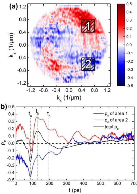
ver-ify the typical pseudospin pattern of the OSHE. This is shown in Fig. 2(a). To reveal the time evolution ofρc
two areas are selected at angles of +45◦ and−45◦ with respect to the direction of the pump. Results for the cho-sen areas are shown in Fig. 2(b), where oscillations with opposite signs ofρc can be observed. This resembles the
behavior [1] originally predicted. However, some striking deviations can be observed. First,ρc in both areas
ini-tially drops to negative values, which we attribute to a small, unavoidable initial polarization of the pump when focussed onto the sample. Second, ρc does not drop to
zero during the initial oscillations in the interval of 150-300 ps. An intuitive explanation for this is the super-position of multiple oscillations with different frequency. This behavior can be understood in terms of the pseu-dospin model which will be discussed in depth in section IV.
Beyond the time evolution of characteristic points of the momentum space, some snapshots at certain points of interest in time merit further investigation, as shown in Fig. 2(b). tacoincides with the initial drop to a negative
ρc. tb denotes the point in time with maximal positive
ρc. Finally tc is selected such that the overallρc of the
total momentum space vanishes although in both areas
[image:2.612.320.571.50.251.2]Figure 2. (a) Time integrated image ofρcin momentum space with marked areas 1 and 2 (b) Time evolution ofρcin selected areas 1 and 2. The recorded time frame starts att0= 0 prior
to the incidence of the excitation pulse.
are shown in Fig. 3. The first snapshot at ta = 87 ps
shows a negative ρc everywhere on the scattering ring.
Since no precession is observable, we conclude that this is the time of excitation when resonant Rayleigh scattering without loss of polarization takes place. The conserva-tion of polarizaconserva-tion under resonant Rayleigh scattering has been observed before.15,17 In the second snapshot in Fig. 3 the totalρc of the momentum space image shows
the largest positive value and the scattering ring is dom-inated by a positiveρc, which also extends into the
mid-dle of the scattering ring due to the energy loss through ongoing scattering processes. The main features of the typical OSHE pattern during the pseudospin precession still remain. The last snapshot in Fig. 3 shows a rather finely segmented picture where points of similar ρc are
[image:3.612.65.288.49.365.2]spread more widely in momentum space. Over the fur-ther course of the scattered beam this behavior stays the same until the intensity is too low to calculate reliable values ofρc.
Figure 3. ρc in momentum space at selected points in time corresponding to the marked points in time of Fig. 2(b).
IV. THEORY
Within the pseudospin formalism the polarization of microcavity polaritons is characterized by the three-component pseudospin vector S = (Sx, Sy, Sz), where
Sx,y,zdescribe the intensities of the linear (collinear with
the original coordinate basis axes components and the di-agonal/antidiagonal ones) and circular polarization com-ponents, respectively. It directly maps to the conven-tional Stokes vector characterizing the polarization of the emitted light.
The evolution of the pseudospin in the scattered state
Sk ≡ Sk(t) characterized by the wave vector k can be
described by the precession equation1,18,25
∂Sk
∂t =Sk×Ωk+f(t)−
Sk
τ (2)
accompanied by the rate equation for the population of the considered state
∂Nk
∂t =f(t)− Nk
τ . (3)
The vector Ωk = (Ωx,Ωy,Ωz) in the first term in the
right-hand side of Eq. (2) describes the effective magnetic field causing oscillatory dynamics of the polariton pseu-dospin components. In our model, the effective magnetic field represents a combination of three fields of different origin:
Ωk=ΩLTk +Ω
an
k +Ω
NL
k . (4)
The LT fieldΩLTk describes the effect of the LT splitting of the linear polarizations and is given by
ΩLTk =
∆LT(k2x−k
2
y), 2∆LTkxky, 0
, (5)
where ∆LT is the LT-splitting constant and kx,y are the
[image:3.612.317.564.53.146.2]the growth direction plays the role of the effective Zee-man splitting of the circularly polarized polariton states. It emerges in Eq. (2) to characterize nonlinear effects during the polariton propagation. Since the polaritons are excited resonantly, the dominant sources of nonlin-earity are polariton-polariton interactions. Accordingly, the effective fieldΩNL
k describes the so-called self-induced
Larmor precession of the polariton pseudospin.29,30 The parameterβ is the effective polariton-polariton interac-tion constant that takes into account the difference of the exchange interaction strengths between two polariton states in the triplet configuration (parallel spins) and the singlet configuration (opposite spins).
The second term on the right-hand side of Eq. (2) de-scribes the inflow of polaritons to the stateSk. Hereafter
we shall account only for the elastic (Rayleigh) scattering of polaritons. We consider the originally studied configu-ration of the OSHE1neglecting multiple scattering effects and assume the stateSk to be fed due to the scattering
from the initial statek0with|k0|=|k|=k. Within this model, the polariton flux is found as1,22
f(t) = 2Sk0
τ1
e−t/τ, (6)
where τ1 is the scattering time describing the scatter-ing of polaritons from the initial statek0 to the statek.
Sk0 is the pseudospin of the initial state. The temporal evolution of the initial state can be found from the equa-tion∂Sk0/∂t=Sk0×Ωk0, where the time dependence of the nonlinear component of the effective magnetic field,
ΩNL
k0, is taken into account in the explicit form.
The last terms in both (2) and (3) describe the radia-tive relaxation due to the finite polariton lifetimeτ in a given state.
Figure 4(a) demonstrates the time evolution of ρc of
the two polariton polarization states corresponding to those in Fig. 2(b). The scattered state wave vector com-ponents arekx=k/
√
2 andky =±k/ √
2 (“+” and “−” correspond to the two observed states scattered at +45◦ and −45◦ with respect to the direction of the pump). Both the dynamics ofρc observed in Fig. 2(b) and
pre-dicted in Fig. 4(a) differ significantly from that calcu-lated in Ref. 1 where the temporal dependencies of ρc
[image:4.612.318.562.51.371.2]for the signal scattered at +45◦ and−45◦ are character-ized by symmetric oscillations with a constant frequency which decay with some characteristic time. This dis-crepancy arises due to the different geometry and ini-tial conditions of our experiment with respect to Refs. 1 and 18. In particular, we need to take into account a slight ellipticity of the pump as follows: Sk0,x(0) =−0.9,
Figure 4. (a) Theoretical prediction of the time evolution of ρc of the two polariton polarization states at angles of +45◦ (the red curve) and −45◦ (the blue curve) with re-spect to the direction of the pump. The solid black curve corresponds to the totalρc integrated over the elastic circle withk = 0.73µm−1. (b) Integratedρc against the scatter-ing angleθ. The parameters used for modelling are: The LT splitting constant is ~∆LT = 18µeV×µm2, the anisotropy
splitting is~δan= 15µeV, the effective interaction strength is
~β=−0.45 meV×µm2. The lifetime of polaritons isτ = 5 ps and the scattering time isτ1= 40 ps.
Sk0,y(0) = (1−Sk20,x)−
1/2 and S
k0,z(0) = 0. The
el-lipticity is caused by the optical setup we have used. In addition, in our caseρcis not zero at the beginning of the
observed time frame. By choosing the initial conditions
Sk(0) that are fitting parameters of the model one can
achieve a better agreement between the modelling results and the experimental data.
According to Fig. 4(a), ρc undergoes oscillatory
dy-namics, herewith one can distinguish two kinds of oscil-lations. The slower oscillations with a period of about 300 picoseconds originate from the pseudospin preces-sion around the effective magnetic field with the oscilla-tion frequency given by Ω = |Ωk|. The fast ones with
Figure 4(b) shows the time-averaged distribution ofρc
around the elastic circle corresponding to the incident pump wave vectork0. The dependence ofρc on the
scat-tering angle θ demonstrates a periodic character. How-ever, in contrast to the predictions of Ref. 1, the positions of the maxima are shifted with respect to the zero-angle direction, θ= 0 which manifests the rotation of the dis-tribution of ρc in the QW plane. Another interesting
difference is that the distribution is biased towards posi-tive values ofρc. The origin of both effects can be traced
back to the impact of the z-component of the effective magnetic field induced by the spin-dependent polariton-polariton interactions. A similar contribution of the z -component to the distribution ofρc has been predicted
theoretically in Ref. 22 for an external magnetic field ap-plied normal to the cavity plane.
V. CONCLUSION
We have experimentally demonstrated the time behav-ior of the OSHE. The observed process can be described within the framework of the pseudospin model developed
assuming a single Rayleigh scattering act per propagat-ing polariton and takpropagat-ing into account the effect of the self-induced Zeeman splitting of polariton states due to spin-dependent polariton-polariton interactions. The po-lariton pseudospin undergoes a characteristic precession around the effective magnetic fields of different origin that results in the oscillatory behavior ofρc of the
emit-ted light.
VI. ACKNOWLEDGEMENTS
We gratefully acknowledge the financial support by the Deutsche Forschungsgemeinschaft in the frame of the ICRC TRR 160 within project B7. The W¨urzburg group acknowledges the support by the Deutsche Forschungs-gemeinschaft within the project SCHN1376-3.1. E.S. ac-knowledges support from the Russian Foundation for Ba-sic Research grant No. 16-32-60104. A.K. and E.S. ac-knowledge support from the EPSRC Hybrid Polaritonics Programme grant. A.K. acknowledges the partial sup-port from the HORIZON 2020 RISE project CoExAn (Grant No. 644076).
1 A. Kavokin, G. Malpuech, and M. Glazov, Phys. Rev.
Lett.95, 136601 (2005).
2
A. Amo, T. C. H. Liew, C. Adrados, R. Houdre, E. Gia-cobino, A. V. Kavokin, and A. Bramati, Nat Photon4, 361 (2010).
3
C. Leyder, T. C. H. Liew, A. V. Kavokin, I. A. Shelykh, M. Romanelli, J. P. Karr, E. Giacobino, and A. Bramati, Phys. Rev. Lett.99, 196402 (2007).
4
D. Ballarini, M. De Giorgi, E. Cancellieri, R. Houdr´e, E. Giacobino, R. Cingolani, A. Bramati, G. Gigli, and D. Sanvitto, Nat Commun4, 1778 (2013).
5
D. Sarkar, S. S. Gavrilov, M. Sich, J. H. Quilter, R. A. Bradley, N. A. Gippius, K. Guda, V. D. Kulakovskii, M. S. Skolnick, and D. N. Krizhanovskii, Phys. Rev. Lett.105, 216402 (2010).
6
D. V. Vishnevsky, D. D. Solnyshkov, N. A. Gippius, and G. Malpuech, Phys. Rev. B85, 155328 (2012).
7
C. Ouellet-Plamondon, G. Sallen, F. Morier-Genoud, D. Y. Oberli, M. T. Portella-Oberli, and B. Deveaud, Phys. Rev. B93, 085313 (2016).
8
T. Freixanet, B. Sermage, A. Tiberj, and R. Planel, Phys. Rev. B61, 7233 (2000).
9 C. Adrados, T. C. H. Liew, A. Amo, M. D. Mart´ın, D.
San-vitto, C. Ant´on, E. Giacobino, A. Kavokin, A. Bramati, and L. Vi˜na, Phys. Rev. Lett.107, 146402 (2011).
10 E. Wertz, A. Amo, D. D. Solnyshkov, L. Ferrier, T. C. H.
Liew, D. Sanvitto, P. Senellart, I. Sagnes, A. Lemaˆıtre, A. V. Kavokin, G. Malpuech, and J. Bloch, Phys. Rev. Lett.109, 216404 (2012).
11 W. Langbein, I. Shelykh, D. Solnyshkov, G. Malpuech,
Y. Rubo, and A. Kavokin, Phys. Rev. B75, 075323 (2007).
12
J. Schmutzler, P. Lewandowski, M. Aßmann, D. Niemietz, S. Schumacher, M. Kamp, C. Schneider, S. H¨ofling, and M. Bayer, Phys. Rev. B91, 195308 (2015).
13 D. Niemietz, J. Schmutzler, P. Lewandowski, K.
Win-kler, M. Aßmann, S. Schumacher, S. Brodbeck, M. Kamp, C. Schneider, S. H¨ofling, and M. Bayer, Phys. Rev. B93, 235301 (2016).
14
M. Aßmann, F. Veit, M. Bayer, A. L¨offler, S. H¨ofling, M. Kamp, and A. Forchel, Phys. Rev. B85, 155320 (2012).
15 R. Houdre, C. Weisbuch, R. P. Stanley, U. Oesterle, and
M. Ilegems, Phys. Rev. B61, R13333 (2000).
16
W. Langbein and J. M. Hvam, Phys. Rev. Lett.88, 047401 (2002).
17
T. Freixanet, B. Sermage, J. Bloch, J. Marzin, B. Gayral, and R. Planel, Physica E: Low-dimensional Systems and Nanostructures7, 676 (2000).
18 C. Leyder, M. Romanelli, J. P. Karr, E. Giacobino, T. C.
Liew, M. M. Glazov, A. V. Kavokin, G. Malpuech, and A. Bramati, Nature Physics3, 628 (2007).
19 M. Maragkou, C. E. Richards, T. Ostatnick´y, A. J. D.
Grundy, J. Zajac, M. Hugues, W. Langbein, and P. G. Lagoudakis, Opt. Lett.36, 1095 (2011).
20 A. Amo, T. C. H. Liew, C. Adrados, E. Giacobino, A. V.
Kavokin, and A. Bramati, Phys. Rev. B80, 165325 (2009).
21
E. Kammann, T. C. H. Liew, H. Ohadi, P. Cilibrizzi, P. Tsotsis, Z. Hatzopoulos, P. G. Savvidis, A. V. Ka-vokin, and P. G. Lagoudakis, Phys. Rev. Lett.109, 036404 (2012).
22 S. Morina, T. C. H. Liew, and I. A. Shelykh, Phys. Rev.
B88, 035311 (2013).
23
K. V. Kavokin, I. A. Shelykh, A. V. Kavokin, G. Malpuech, and P. Bigenwald, Phys. Rev. Lett.92, 017401 (2004).
24 G. Nardin, T. K. Para¨ıso, R. Cerna, B. Pietka, Y. L´eger,
O. El Daif, F. Morier-Genoud, and B. Deveaud-Pl´edran, Applied Physics Letters94, 181103 (2009).
25 M. M. Glazov and L. E. Golub, Phys. Rev. B77, 165341