doi:10.4236/ijcns.2010.33034Published Online March 2010 (http://www.SciRP.org/journal/ijcns/).
Performance of Block Diagonalization Broadcasting
Scheme for Multiuser MIMO System Operating in
Presence of Spatial Correlation and Mutual Coupling
Feng Wang, Marek E. Bialkowski, Xia Liu
School of Information Technology & Electrical Enginnering, University of Queensland, Brisbane, Australia Email:{fwang, meb, xialiu}@itee.uq.edu.au
Received December 31, 2009; revised January 30, 2010; accepted February 27, 2010
Abstract
In this paper, the capacity of a multiuser Multiple Input Multiple Output (MIMO) system employing the block diagonalization broadcasting scheme in presence of spatial correlation and mutual coupling is investi-gated. It is shown by computer simulations that, in general, the presence of spatial correlation decreases the capacity of a multiuser MIMO system. However, for some particular antenna element spacing mutual cou-pling decreases the spatial correlation rendering an increased capacity. The optimized diagonalization broadcasting technique with a two-stage power allocation scheme is proposed and verified. The presented simulations results confirm the advantage of the proposed broadcasting scheme.
Keywords: Multiuser MIMO, Block Diagonalizaiton, Mutual Coupling, Dirty Paper Coding
1. Introduction
It has been shown via theoretical derivations as well as by experiment that using multiple element antennas with a suitable signal transmission scheme in a rich scattering propagation environment can enhance peer-to-peer com- munication without the use of extra frequency bandwidth [1,2]. This potential of multiple input multiple output (MIMO) communication systems can be used to advan-tage using two alternative approaches. In one approach, the signal transmission quality via diversity can be im-proved. Alternatively for a chosen quality factor such as bit error rate (BER), the data rate can be increased by a stream multiplexing transmission.
Most recent studies on MIMO focus on multiuser sys-tems. For a multiuser MIMO system, allocation of the channel resources among independent users either in the form of multiple accesses (uplink) or broadcasting (dow- nlink) is considered. The information theory hints that the broadcasting case is by far the most challenging. In this case, an inter-user interference occurs due to the spatially multiplexed transmitted signals at a base station (BS). For the Gaussian MIMO broadcasting channels, it has been proved that dirty paper coding (DPC) [3] can achieve the available capacity [4]. However, to deploy DPC in a real system is challenging due to the high com-plexity and computational burden on successive
encod-ing and decodencod-ing. An alternative strategy is the block diagonalization (BD) [5,6]. Compared with DPC sche- me, BD is a suboptimal technique with much reduced complexity. Using this technique, signals are transmitted only to desired users. In turn, null steering is applied to other users by decomposing the multiuser channel into a group of parallel single user MIMO channels. To achieve such decomposition, BS needs to select a suitable beam-forming matrix for each user. The matrix is vertical to the space spanned by other users’ channels matrices. If the channel matrices of all the scheduled users are per-fectly known at the transmitter, the inter-user interfer-ence can be eliminated by BD, rendering a simple re-ceiver structure.
MIMO transceiver has to be of compact size interactions within the transmitting or receiving array antennas have to be taken into account. The small inter-element spacing in the antenna array in such transceivers renders mutual coupling. The effect of mutual coupling on a point- to-point MIMO system has been investigated in many works, such as [9,10,11]. In this paper, a BD algorithm that accounts for the effect of spatial correlation and mutual coupling in array antennas is presented and its performance is evaluated with respect to the overall sys-tem capacity.
The paper is organized as follows. Section 2 describes a multiuser MIMO system model including the channel model with spatial correlation. Section 3 describes inter-actions between the array elements and scatterers in the propagation environment in which mutual coupling ef-fects cannot be neglected. Section 4 gives details of the BD algorithm that accounts for the effect of mutual cou-pling. Section 5 quantifies the effect of mutual coupling by presenting numerical results. Section 6 summarizes the findings of the undertaken research.
2. System Model
2.1. Signal Model
A narrowband multiuser system is assumed. It is postu-lated that it is created around a base station (BS) with L downlink mobile users. The base station includes N transmitting antennas. At time t, K mobile stations (MS) from L available users are scheduled to be serviced by BS. The k-th mobile station (MS) employs Mk antennas. The transmitted signal intended for the k-th mobile sta-tion is denoted by a Qk × 1 dimensional vector xk which
is weighted by an N × Qk pre-processing matrix Wk
be-fore transmission. Qk is the number of parallel data symbols transmitted simultaneously to the k-th MS. The MIMO channel between the BS the k-th MS is described by the complex matrix Hk, whose (i,j)th entries represent
the complex gain between the j-th transmit antenna at BS and i-th antenna at k-th MS. It is assumed that different MS experience independent fading. The received signal at k-th MS can be presented by
1
1, K
k k k k k k
k
K
k k k k k j j j k j j k
y H W E x n
H W E x H W E x n (1)
where trace(EkE†k) =pk is the power transmitted to the kth
MS. nk is the additive Gaussian white noise (AWGN)
vector, whose elements are independent identical distri-bution (i.i.d.) zero-mean circularly symmetric complex Gaussian random variables with variance σn2.
2.2. Channel Model
The channel matrix Hk describing the channel properties
between BS and the kth MS is influence by the transmit-ting and receiving antenna array configurations and a signal propagation environment. It is assumed that the BS and MSs are equipped with wire dipoles arranged in liner arrays. The length of each dipole element is as-sumed to be half wavelength. Also, the links between BS and different MSs do not share the same scattering envi-ronment. This assumption confirms the earlier assumed independent signal fading for different MSs. For each link, the Kronecker channel model [5,12] is assumed. In this model, the correlations at transmitter and receiver sides are independent and the channel matrix Hk is
rep-resented as
k 1/ 2 1/ 2k MS H
H R G RBS (2) where GH is a matrix with i.i.d. Gaussian entries with zero mean and unit variance and k
MS
R and RBS are
spa-tial correlation matrices at the kthMS and BS, respec-tively. In a rich scattering environment, the correlation for any pair of dipole element with spacing dm,n can be
obtained using Clark’s model and are given by a Bessel function
, 0
(
,m n
J kd
m n)
(3) Using (3), the correlation matrix for the kth MS can be generated as1,1 1,
,1 ,
k
k k
M k
MS
M M
k
M
R
(4)
In turn, the correlation matrix for BS can be obtained from
1,1 1,
,1 ,
N BS
N N
N
R
(5)
3. Mutual Coupling
For the array formed by linear parallel wire dipoles, the mutual coupling matrix can be expressed using electro-magnetic and circular theory described in [9]
1 (ΖA ΖT)( T M)
Z
C I (6)
where ZA = 73 + j42.5[Ω] is the element impedance in
isolation and ZT is impedance of the receiver at each
ele-ment. It is chosen to be the complex conjugate of ZA to
matrix with all the diagonal elements equal to ZA + ZT, its
non-diagonal elements Znm are decided by the physical
parameters including dipole length, the horizontal dis-tance between the two dipoles. For a side-by-side array configuration and dipole length l equals to 0.5λ, Znm is
given by [9,10]
0 0 1 1 2 2
30 0.5722 ln(2 ) (2 )
30 (2 ) ,
30 2 ( ) ( ) ( )
302 ( ) ( ) ( )
i i
mn
i i i
i i i
l C l
m n
j S l
Z
C u C u C u
m n
j S u S u S u
(7)
where β=2π⁄λ is the wave number and Ci(u) and Si(u) are
the cosine and sine integral, respectively, given as
0cos( ) ( ) u i u i x
C u dx
x sin x
S u dx
x
(8) and the constants are given by [10]
0 2 2 1 2 2 2 h h h u du d l
u d l
l l (9)
where dh is the horizontal distance between the two
di-pole antennas.
4. Block Diagonalizaiton with Mutual
Coupling
We assume at time t, K mobile stations (MS) from L available users are scheduled to be serviced by BS. To ensure the sufficient freedom for BS to perform BD over the K scheduled MSs, it is assumed that
1 K k k M N
(10) With spatial correlation and mutual coupling taken into account, the received signal at kth MS described by (1) can be rewritten as
1/ 2 1/ 2 1 1/ 2 1/ 2
1/ 2 1/2 1, K k k
k MS MS BS BS k k k k k
k k
MS MS BS BS k k k K k k
MS MS BS BS j j j k
j j k
H H Hy C R G R C W E x n
C R G R C W E x
C R G R C W E x n
(11)
where, CBS and CkMS are the mutual coupling matrices for the dipole element array at BS and the kth MS, re-spectively. Wk is the beamforming matrix at BS for the
kth MS. To eliminate the interference from the signals transmitted to other MSs, the key idea in the block di-agonalization is to zero-force the interference by impos-ing the followimpos-ing condition
1/2 1/2( ,1 ,
k k
MS MS H BS BS j j k k j K
C R G R C W 0 ) (12)
when the mutual coupling and correlation is taken into account,
1/ 2 1/ 21 2 1 2
[ , , , ]
[ , , , ]
k k
k MS MS BS B
T K K H
H C R G R C
H H H H
W W W W
S
(13)
where (•)T donates the matrix transpose operation. By including the condition given by (12), the effective chan-nel matrix for the multiuser MIMO system with K MSs can be represented by a ∑Mk × ∑Mk matrix, given as
1 1 1 2 1
2 1 2 2 2
1 K K K K K D HW
H W H W H W
H W H W H W
H W H W
(14)
By using (12), Equation (14) can be rewritten as
1 1 2 2 K K
H W 0 0 0
0 H W 0 0
D
0 0 0
0 0 0 H W
(15)
At this point it is important to comment whether the condition (12) can be met in practice. From the theory of antennas it is known that an N-element array antenna is capable of forming N-1 nulls. This means that in the strict sense, the BS having an N-element array is able only to null up to N-1 MSs. For a larger number of MSs, the condition (12) has to be compromised. In such a case, the BS can direct low sidelobes instead of nulls towards undesired users. In further considerations, it is assumed that the number of MSs served by BS is such that the condition (12) is met.
4.1. Calculation of Beamforming Matrices
In order to transmit a signal only to the desired MS while steering nulls to the remaining MSs, the beamforming matrix for the desired MS should be orthogonal to the space spanned by the channel matrices of the undesired MSs. We define the channel matrix as
1 1 1
[ , , , T
k k k
which is obtained by removing the channel matrix for the kth MS from . Performing the eigenvalue decomposi-tion (EVD) over the N × N non-negative Hermitian Ma-trix, one obtains
H
† †
†
[ ] k
k k k k
k
Σ 0 V H H V V
0 0 V
(17)
where (•) † denotes the conjugate transpose operation. It can bee seen that Vk is a matrix with the dimension
of N × Mk. Its columns correspond to those zero
eigen-values. By letting Wk = Vk, a perfect null steering to all
the undesired K-1 MSs can be achieved. By repeating the steps represented by Equation (15) and (16), all the K beamforming matrices can be obtained. In this way, as shown in Equation (14), the multiuser MIMO downlink system is decomposed into K independent single-user MIMO systems.
4.2. Overall Capacity of Multiuser MIMO Broadcasting with Block Diagonalization
For the case of a multiuser MIMO downlink system which is decomposed into K independent single-user MIMO systems by block diagonalization, the overall capacity can be obtained as a sum of individual links capacities, as expressed by
† † †
2 2
1
1 log det K
k
sum k k k k k k
k n
C
I E W H R H W Exx
(18)
With mutual coupling and spatial correlations taken into account, (18) can be rewritten as
† † †
2 2
1
1 log det
K
k
sum k k k k k k
k n
C
I E W H R H W Exx (19)
where is the kth MS’s input covariance matrix. The capacity for kth MS is
k xx R
† † †
2 2
1
log det k
k k k k
n
C
I E W H R H W Exx k k k (20)
We assume that the signal intended for the kth MS is a Gaussian signal. As a result, (20) can be simplified to
† †
2 2
† † † †
2 2
log det
log det
k
k k k k k
n k
k BS k MS MS k BS k n
p C
p
I W H H W
I W C H C C H C W
For high SNRs, (21) can be further simplified and given by
† † † †
2 2
† †
2 2
† †
† † †
2 2 2
† log det
log det
det det
log det log det
det
k
k k BS k MS MS k BS k
n k
k k k k n
MS MS BS BS k
k k k k MS MS
n BS BS
p C
p
p
W C H C C H C W
W H H W
C C C C
W H H W C C
C C
(22)
The last part of Equation (22) shows three terms con-tributing to the capacity. The first term represents the broadcasting capacity for the kth MS without the effect of mutual coupling at BS and MS. The second and third terms represent the mutual coupling at kth MS and BS. The effect of these terms on capacity depends on the coupling matrices at the MS and BS ends. If the product of the determinants of the mutual coupling matrices is larger than one, the effect of mutual coupling on capacity is positive. Otherwise, it is negative.
4.3. Power Allocation Scheme
The most straightforward power allocation scheme from BS to different MSs is accomplished by transmitting equal power to each MS. That is
†
trace( ) T
k k k
P p
K
E E (23)
where PTis the total transmitted power at BS and pk is
the power allocated to the kth MS.
This power allocation scheme is simple to realize in practice. However, it does not always provide the best performance with respect to capacity. To maximize the capacity, a two-stage power allocation scheme is pre-sented. At the first stage, the power allocation is accom-plished according to the objective function at the users’ level, as expressed by
1, 2, , 1 2
1
Max , , ,
K sum K
p p p K
k T k
C p p p
Subject to p P
(24)
(21)
The result of (24) is the optimized power allocation for different users under service. This is the capacity-greedy power allocation scheme and is non-linear. The solution can be obtained by applying a Lagrange method.
different transmit antennas according to the objective function, which is described by
2
1
, 1, 2, ,
i n
k k i
k r
i k k i
p i
Subject to p p
r
(25)
where (z)+=max(0,z) and μ
k is chosen to obey the power
constraint for the kth MS and r is the rank of the effec-tive channel matrix between BS and the kth MS
1/ 2 1/ 2
rank k k
MS MS BS BS k
r C R G R C WH (26)
By applying the water-filling scheme, the capacity for kth MS is
22 1
1 log 1
r
i
k k k
i n
C
n
(27)5. Numerical Results
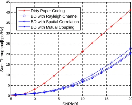
Using the presented theory, computer simulations are performed for a multi-user MIMO system with 8 trans-mit antennas at BS and 3 MSs each equipped with 2 re-ceive antennas. It is assumed that the three MSs are scheduled and served by BS at the same time. As a result, this system is referred to as a 3 × (2 × 8) system.
Figure 1 presents the possible impact of spatial corre-lation and mutual coupling on the broadcasting through-put. In simulations, the dipole spacing at BS and MS is assumed to be fixed at 1.0λ and 0.5λ, respectively.
As observed from the results presented in Figure 1, Dirty Paper Coding, where effects of spatial correlation and mutual coupling are neglected, offers the largest
-5 0 5 10 15 20
0 5 10 15 20 25 30 35 40 45
SNR[dB]
S
um
T
hr
oughput
[bps
/H
z
]
[image:5.595.59.290.514.698.2]Dirty Paper Coding BD with Rayleigh Channel BD with Spatial Correlation BD with Mutual Coupling
Figure 1. Broadcasting throughput for a 3 × (2 × 8) system.
scheme in which spatial correlation and mutual coupling are neglected shows a reduced throughput. The through-put for BD with mutual coupling or spatial correlation included in calculations further reduces the system throu- ghput. The differences are most pronounced at larger levels of SNR.
Figure 2 shows the effect of spatial correlation and mutual coupling on the broadcasting throughput for a 3× (2×8) system. The SNR is set to 10 dB and the unit for dipole spacing is the wavelength, represented by λ. The solid lines represent CDF of broadcasting throughput with spatial correlation only and the dotted lines are for the CDF of broadcasting throughput with spatial correla-tion and mutual coupling combined. It can bee seen form Figure 2 that the presence of spatial correlation and mu-tual coupling results in a degraded broadcasting throug- hput in comparison with an idealized Rayleigh channel. .
In general, spatial correlation is regarded as a negative factor in a MIMO communication system. However, mutual coupling can be seen as a positive factor at some dipole spacing. As observed in Figure 2, for the dipole spacing of 0.2λ and 0.3λ, the existence of mutual cou-pling results in a higher capacity. It is interesting to note that the curve of the capacity with and without mutual coupling merge at the point of dipole spacing equal to 0.4λ. When the spacing is increased to 0.6λ, the plot rep-resenting the capacity with mutual coupling is on the left side of the curve for the capacity with correlation only. This is the case for which the presence of mutual cou-pling leads to a lower capacity.
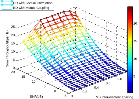
Figures 3 and 4 show comparisons between capacity with spatial correlation only, and with spatial correlation plus mutual coupling, as a function of antenna element spacing.
In the presented simulation results, the SNR is set to
6 7 8 9 10 11 12 13 14 15
0.1 0.2 0.3 0.4 0.5 0.6 0.7 0.8 0.9 1
Sum Throughput[bps/Hz]
CD
F
Dipole Spacing =0.2 No MC Dipole Spacing =0.2 With MC Dipole Spacing =0.3 No MC Dipole Spacing =0.3 With MC Dipole Spacing =0.4 No MC Dipole Spacing =0.4 With MC Dipole Spacing =0.6 No MC Dipole Spacing =0.6 With MC Rayleigh Channel Dipole Spacing =0.2
Dipole Spacing =0.3
Dipole Spacing =0.6
Dipole Spacing =0.4
0.1 0.2 0.3 0.4 0.5 0.6 0.7 0.8 0.9 1 6
6.5 7 7.5 8 8.5 9 9.5
Dipole spacing
S
um
T
hr
oughput
[bps
/H
z
]
[image:6.595.312.537.75.239.2]BD with Spatial Correlation BD with Mutual Coupling
Figure 3. Broadcasting throughput vs. MS array interele-ment spacing for a 3 × (2 × 8) system.
0 0.2
0.4 0.6
0.8 1
-5 0 5 10 15 20
0 5 10 15 20 25
MS Inter-element spacing SNR(dB)
S
u
m
T
h
ro
ug
hp
ut
(b
ps
/H
z
)
5 10 15 20 BD with Spatial Correlation
[image:6.595.61.286.77.256.2]BD with Mutual Coupling
Figure 4. Broadcasting throughput vs. MS array interele-ment spacing and SNR for a 3 × (2 × 8) system.
10 dB and the unit for dipole spacing is the wavelength, as represented by λ. The dipole spacing ranges from 0.0λ to 1.0λ. We can see that the curves for BD with spatial correlation only and BD with spatial correlation plus mu-tual coupling cross at 0.4λ and 0.95λ. For the dipole spacing range from 0.4λ to 0.95λ, mutual coupling in-creases the spatial correlation level and results in a de-creased capacity. In turn, when the dipole spacing ranges from 0.1λ to 0.4λ, mutual coupling decreases the spatial correlation level and renders an increased capacity.
The results presented in Figures 5 and 6 verify the two-stage power allocation scheme described inSection 6.
One can see from results presented in Figures 5 and 6 that with or without mutual coupling, the optimized power allocation scheme leads to a higher capacity than the non-optimized one over the SNR range from 5 dB to 20 dB and the antenna spacing from 0.1λ to 1λ. The
0 0.2 0.4 0.6 0.8 1 -5
0 5
10 15
20 0
5 10 15 20 25 30
MS Inter-element spacing SNR(dB)
S
um
T
hr
ou
ghpu
t(
b
ps
/H
z
)
5 10 15 20 25
Optimized Broadcasting Throughput
[image:6.595.60.288.308.471.2]Non-optimized Broadcasting Throughtput
Figure 5. Comparison of optimized and non-optimized broadcasting throughput vs. MS array interelement spacing and SNR for a 3 × (2 × 8) system in the presence of spatial correlation only.
0 0.2 0.4 0.6 0.8 1
-5 0 5 10 15 20 0
10 20 30
SNR(dB) MS Inter-element spacing
S
um
T
hr
o
ughp
ut
(bps
/H
z
)
5 10 15 20 25 Optimized Broadcasting Throughut
Non-optimized Broadcasting Throughut
Figure 6. Comparison of optimized and non-optimized broadcasting throughput vs. MS array interelement spac-ing and SNR for a 3 × (2 × 8) system in the presence of spa-tial correlation and mutual coupling.
optimized scheme improves capacity in the presence of spatial correlation and mutual coupling. This achieve-ment is more apparent at higher values of SNR and lar-ger inter-element antenna spacing.
6. Conclusions
[image:6.595.311.536.312.475.2]correla-tion leads to a decreased capacity. However, mutual cou-pling may have negative or positive influence of capacity. For some particular dipole spacing range, mutual cou-pling decreases the spatial correlation level, rendering an increased capacity. The optimized diagonalization broad- casting technique with a two-stage power allocation scheme has been proposed and verified. The presented simulations results have demonstrated a positive impact of this optimized BD scheme.
7. Acknowledgment
One of the authors (F. Wang) acknowledges the support of the University of Queensland in the form of Interna-tional Postgraduate Research Scholarship (IPRS).
8. References
[1] G. J. Foschini and M. J. Gans, “On limits of wireless co- mmunications in a fading environment when using mul- tiple antennas,” Wireless Personal Communications, Vol. 6, pp. 311–335, 1998.
[2] E. Telatar, “Capacity of multi-antenna Gaussian chann- els,” European Transactions on Telecommunications, Vol. 10, No. 6, pp. 585–596, November 1999.
[3] M. Costa, “Writing on dirty paper,” IEEE Transactions on Information Theory, Vol. 49, No. 3, pp. 439–441, May 1983.
[4] W. Weingarten, Y. Steinberg, and S. Shamai, “The capa- city region of the Gaussian multiple-input multiple-output broadcast channel,” IEEE Transactions on Information Theory, Vol. 52, No. 9, pp. 3936–3964, September 2006. [5] Q. H. Spencer, A. L. Swindlehurst, and M. Haardt, “Zero-
forcing methods for downlink spatial multiplexing in multi-user MIMO channels,” IEEE Transactions on Infor- mation Theory, Vol. 42, No. 3, pp. 461–471, February 2004.
[6] L. U. Choi and R. D. Murch, “A transmit preprocssing technique for multi-user MIMO systems using a decom- position approch,” IEEE Transactions on Wireless Com- munications, Vol. 3, No. 1, pp. 20–24, January 2004. [7] K. Zhang and Z. Niu, “Multiuser MIMO downlink trans-
mission over time-varing channels,” Proceedings Interna- tional Conference on Communications, pp. 5514–5518, June 2007.
[8] S. Shim, J. S. Kwak, R. W. Heath, and J. Andrews, “Block diagonalization for multi-user MIMO with other-cell interference,” IEEE Transactions on Wireless Commun- ications, Vol. 7, No. 7, July 2008.
[9] S. Durrani and M. E. Bialkowski, “Effect of mutual coupling on the interference rejection capabilities of linear and circular arrays in CDMA systems,” IEEE Transactions on Antennas and Propagation, Vol. 52, No. 4, pp. 1130–1134, April 2004.
[10] M. E. Bialkowski, P. Uthansakul, K. Bialkowski, and S. Durrani, “Investigating the performance of MIMO sys- tems from an electromagenetic perspective,” Microwave and Optical Technology Letters, Vol. 48, No. 7, pp. 1233 –1238, July 2006.
[11] F. Wang, M. E. Bialkowski, and X. Liu, “Investigating the effect of mutual coupling on SVD based beam- forming over MIMO channels,” International Journal on Signal Processing, Vol. 3, No. 4, pp. 73–82, July 2009. [12] C. N. Chuah, D. N. C. Tse, and J. M. Kahn, “Capacity