Energy distribution modulation by mechanical design for
electrochemical jet processing techniques
Jonathon Mitchell-Smith1, Alistair Speidel1 Jennifer Gaskell2 Adam T. Clare1*
1 Advanced Component Engineering Laboratory (ACEL), Advanced Manufacturing Technology Group, University of Nottingham, Nottingham, NG7 2RD, United Kingdom.
2 Centre for Mathematical Medicine and Biology, School of Mathematical Sciences, University of Nottingham, Nottingham NG7 2RD, United Kingdom
*Corresponding Author: Adam Clare, [email protected]
Abstract
analogous to traditional milling profiles. Since electrode design can be rapidly modified EJP is shown to be a flexible process capable of varied and complex meso-scale profile creation. Innovations presented here in the modulation of resistance in-jet have enabled electrochemical jet processes to become a viable, top-down, single-step method for applying complex surfaces geometries unachievable by other means.
Nomenclature
ds minimum distance of the nozzle tip from the surface (μm) STD
standard nozzle type
dn specific distance of the individual modified nozzle feature from the surface (μm)
CPE centre point element nozzle design
AA annulus area of nozzle tip surface facing the incident surface (mm2)
WC wide castellated nozzle design AF area of current focussing feature
facing the incident surface (mm2)
NC narrow castellated nozzle design
Aexp area of profile expected from calculation (mm2)
𝐸𝑒𝑓𝑓 electrolyte current efficiency
(%)
V voltage (V) ECE electrochemical equivalent I current (A) J current density (A/cm2)
R resistance (Ω) m mass (g)
pr probability of removal L length (m) S Single point or element on the
substrate facing the nozzle tip element (N)
DIF design impact factor
N Single point or element on the surface of the nozzle tip facing the substrate surface (S)
rnoz radius of the nozzle (mm)
I.D. inner diameter of the nozzle (mm) O.D. outer diameter of the nozzle (mm)
STE symmetrical twin element nozzle design
tm total machining time OSPE Off-centre single point element
1. Introduction
The creation of next-generation, high-integrity surfaces [1-3] presents a significant manufacturing challenge. Advantage can be gained for anti-fouling, drag-reduction, enhanced adhesion [4, 5] and enhanced osseointegration [6, 7] in applications where complex surface structuring has been employed.
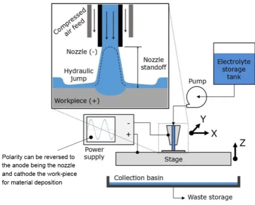
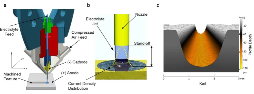
Electrolyte jet processing (EJP) is the amalgamation of electrochemical jet machining (EJM) [13-15] and electrochemical jet deposition (EJD) [16, 17], within a unified machine tool. This technique can achieve jetted deposition of material with a cathodic workpiece, and jetted material removal with an anodic workpiece (Figure 1a). Manipulation of process parameters, polarity and electrolyte chemistry enables application-specific, bespoke surface-structuring to be generated in a single process step.
To date, capability of the EJP process is fundamentally limited as a result of the characteristic energy density profile, which results from the use of ‘standard’ nozzles. Through modelling and experimentation of adaptations to the process, new capabilities are demonstrated here and qualified from first principles.
1.1. In-jet modulation of current distribution
Consistent with other energy beam processes such as laser [18], electron [19] or water jet [20] the energy density is typically seen to be of a Gaussian spatial distribution (Figure 1b). This extends radially outward from a peak intensity at the centre of the beam. The resulting profiles exhibit tapered sides, a rounded apex and diffused edge definition (Figure 1c). Significant work
Figure 1: (a) EJP end-effector in subtractive polarity configuration (material removal) as used in this demonstration. (b) Standard nozzle showing the standard Gaussian type current density profile within the
incident jet. (c) 3D surface map from experimental results showing the profile currently achieved from a standard cylindrical nozzle reflecting the Gaussian profile of energy distribution. demonstrating the tapered
[image:4.595.86.525.219.381.2]has been undertaken in the field of laser processing to modify energy distributions. Through beam profile shaping, more favourable and uniform thermal distributions [21-23] have been produced. In this case, holographs generated by custom optics are used to define the incident energy distribution. This can be considered as optically analogous to the work presented here.
Although EJM has been demonstrated to be capable of biomimetic type structures in the form of super-hydrophobic surfaces [24], EJP is currently limited by a characteristic energy profile (Figure 1b). This is the principle factor in determining the dissolution profile [15]. By adapting this energy distribution, it is proposed that distinct meso- and micro-surface geometries can be created.
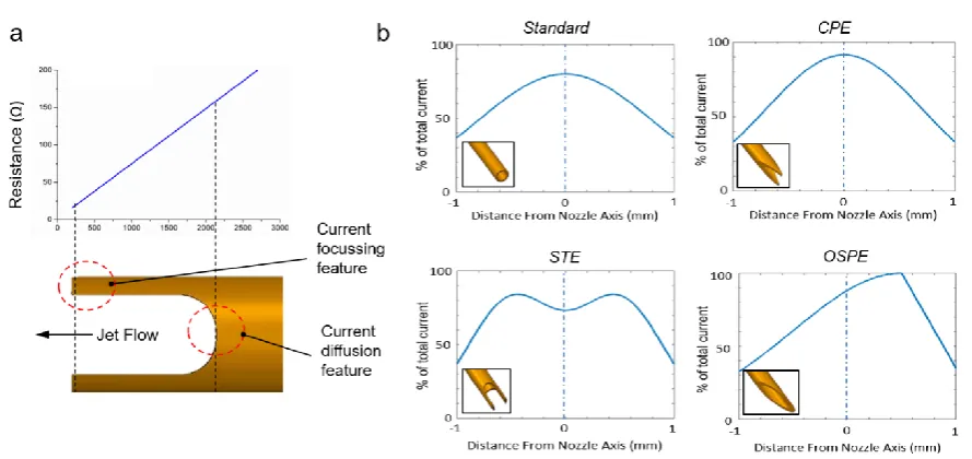
Found experimentally, Figure 2a shows that when using a standard profile nozzle, resistance increases from 15 Ω at a nozzle stand-off of 200 µm through to 200 Ω at 2.75 mm stand-off when used with a 2.3 M NaNO3 electrolyte. This can then be related to localised resistance at
nozzle tip features. Adjacent to this (Figure 2b) is the expected 2D distribution as a percentage of the total charge created by proposed new nozzle geometries. Utilising the measured resistance data from Figure 2a it is possible to calculate the percentage of total charge available (Equation 1). Using the minimum and maximum points of current created by the nozzle features, a Gaussian distribution is then assigned around these giving an approximation of the current distribution. The area under the curve being equal to the total current density. This is, in turn, is proportional to the total material removed across the 2D section.
𝑉 = 𝐼𝑅 = 𝜋𝑟
𝑛𝑜𝑧2𝐽𝑅
[1]Figure 2: (a) By redesigning the geometry of the nozzle tip, localised resistance can be modulated in-jet thus allowing current distribution to be manipulated. For the first time this leads to a change in the profile removed. (b) graphical representations of the current distribution expected from the CAD designs in the bottom left corner of the graph creating preferential current paths by lowered localised resistance at discreet points. This
[image:6.595.75.520.450.660.2]Significant prior work has been carried out in the development and deployment of simulations of energy beam processes. A wide range of mathematical models to explain material removal and induce optimisation in comparative processes such as abrasive water-jet (ABWJ) [25-28], sandblasting [29], pulsed electron beam ablation (PEBA) [30], laser ablation [31, 32] and fluid jet polishing [33, 34] have been presented, each with specifics relative to the process in question. Previous work, in both removal and deposition electrochemical jet methods, has provided insight into the basic current distribution found with a standard cylindrical nozzle [35, 36] and expanded to three dimensions [37]. Increasing temperature from joule heating and changing electrolyte conductivity has been included [38] alongside the influence of varying nozzle diameter [39] and dynamic jet shape as a function of an eroding surface [40]. Further still a multiphysics approach has been undertaken and expanded to include fluid-dynamics, electro-dynamics and geometry deformation leading to ejection and secondary machining effects [41, 42]. These models are all based on the assumption of a static, cylindrical Gaussian energy distribution and have produced reliable results [43, 44]. However, adaptations are required to underpin this investigation. In order to utilise this new capability, advances must be made to the established process models.
The methodology is further applied to smaller scale nozzles to investigate scalability of feature size. Using the smaller scale nozzles also enables greater variation in process parameters. Therefore, it was possible to carry out an investigation to see if the influence of current density and electrolyte jet speed had any effect on the general response profile of a specific nozzle design.
This novel approach to electrolyte jet processing techniques is aimed to expand the application of EJP in large area surface structuring and micromachining through enhanced process flexibility of an already scalable and economically-viable technique.
1.2. Simulation of in-jet resistance modulation
Simulation using a variation of two-dimensional nozzle tip designs was undertaken to assess whether the addition of modulating in-jet resistance could be achieved.
In order to understand the modulation of in-jet resistance from various two-dimensional nozzle tip designs, a MATLAB model was developed. This simulated the jet interaction environment between tool and target surface. Variance can be seen in experimental work, even across the length of the sample. This arises due to the natural fluctuations from valence variation, hydrodynamic effects, including wash away of large undissolved precipitates, and grain boundary effects. The model captures this stochastic nature of EJM through probabilistic dissolution.
The current density distribution for each nozzle is calculated from the resistance generated as
a function of distance from nozzle tip to contour as described in Section 1.1. Using these 2D
representations, the current distribution can be applied to the progressing dissolution.
The electrolysis model was constructed from Faraday's First Law of Electrolysis, which gives the expected value for mass removed (in grams) to be:
𝑚 = ∫ 𝐼(𝜏)𝑀
𝐹𝑧 𝑑𝜏 [2] 𝑡𝑚
0
where 𝑡𝑚is the total machining time, 𝐼(𝜏) is the current integrated over time step 𝜏, M is the
molar mass, F is Faradays constant and z is the material valence.
The total cross-sectional area expected to be removed is thus:
𝐴𝑒𝑥𝑝 = ∫ 𝑚(𝑥)
𝜌𝐿 𝐸𝑒𝑓𝑓𝑑𝑥, [3]
where x is the distance across the cross-sectional area in the x co-ordinate (Figure 4),
𝜌
isthe material density of a single 2D section within the profile (m2), and
𝐸
𝑒𝑓𝑓 is the electrolyte
current efficiency (%) calculated from prior experimental work on material removal rates [45] and compared to theoretical mass removal
m
.The model removes elements of the substrate stochastically with respect to a probability of removal (
𝑝
𝑅)
which is governed by supplied current density, electrolyte, electrochemical equivalent (ECE) of the material elements and condition of neighbouring elements (Equation 4). The basis of the simulation is shown in Figure 3.𝑝
𝑅=
𝐸𝐶𝐸∙𝐼(𝑥)𝑑𝑡Figure 3: A flow chart of the stochastic simulation process as described in the text. If a surface element is exposed and the probability of removal is greater than a random number, r∈[0,1], then the element will be dissolved.
For each time step, each exposed element of the surface will have a respective probability of removal compared to a random number, 𝑟 ∈ [0,1]. If 𝑝𝑅< r, the element is not dissolved. This
process continues until the total machining time (tm) has been applied (with 𝑝𝑅 scaled accordingly), or alternatively, until the total area removed across the 3D surface approximates the area expected, Aexp. The model provides a predicted surface profile for any nozzle
geometry, nozzle distance, and current density combination.
Figure 4: Normalised 3D simulations of the expected striation profile created by stacking re-iterated sim profiles along a striation length (L), considering the dissolution effect caused by the current distribution at each
discreet point across the kerf (x) for (a) standard nozzle, (b) centre point element (CPE), (c) off-centre single point element (OSPE) and (d) symmetrical twin element (STE)
1.3. Nozzle design definition
Novel nozzles were created to establish non-standard energy distributions mimicking those used in the initial simulation. Two separate approaches were taken to the design of the nozzle tips. Firstly, a planar approach to design was taken to establish the influence of changing the distance between the nozzle rim contour and the interaction surface. Secondly, a free-form approach was taken to assess the influence of the area of each nozzle contour feature facing the interaction surface.
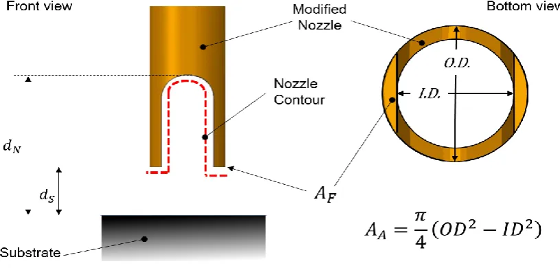
This is termed the nozzle design impact factor (DIF). This takes into consideration not only the distance of the parallel surface of the nozzle to the workpiece surface but also the area of the nozzle surface. This is expressed in Equation 5.
𝑫𝑰𝑭 =
𝑨𝑭𝑨𝑨
.
𝒅𝑺𝒅𝑵
[5]
Where AF is the area of the specific feature facing the surface and AA is the annulus area of
the nozzle tip, dS is the minimum distance of the nozzle tip from the surface and dN being the
distance of the individual nozzle feature from the surface (Figure 5).
[image:12.595.82.490.343.538.2]Higher DIF values will therefore lead to higher localised material removal due to lower localised resistance. This in turn means a lower voltage is required to generate the determined current density within the jet. Using the DIF value allows the performance of nozzle features to be evaluated and their weighted effect on the resultant profile to be predicted.
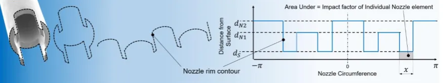
The relationship seen in Equation 5, although useful in assessing design elements of a simple nozzle design feature, is required to be expanded to address more complex designs (Equation 6). It is possible to assess the impact of the nozzle as a whole or any individual feature by quantifying the area under the contour of the nozzle. Effectively the larger the area, the larger the resistance and so the lower the impact (Figure 6).
𝑫𝑰𝑭
𝑛𝑜𝑧𝑧𝑙𝑒(𝑥) = ∫ ∫
𝑑𝑆𝑑𝑁𝑆(𝑥,𝑧,𝜃)
𝑑𝑧 𝑑𝜃
𝑧0 𝜋
−𝜋
,
[6]
where 𝑑𝑁𝑆 is the Euclidean distance between a nozzle element (N) and substrate surface
element (S), located at (
𝑥
𝑁, 𝑦
𝑁, 𝑧
𝑁)
and (𝑥
𝑆, 𝑦
𝑆, 𝑧
𝑆)
,
𝑑
𝑁𝑆(𝑥, 𝑧, 𝜃) = √∆𝑥
2+ ∆𝑦
2+ ∆𝑧
2= √(𝑥
𝑆− 𝑥
𝑁)
2+ 𝑑
𝑁2
+ (𝑧
𝑆− 𝑧
𝑁)
2,
[7] [image:13.595.78.516.483.565.2]as the height of the surface is taken as
y
s= 0.Figure 6: Graphical representation of the extended DIF equation for evaluation of a single element of the NC nozzle
The contour of the nozzle is removed from the design intent and unravelled into a two-dimensional profile, the abscissa being the circumference of the nozzle and the ordinate being the distance from the interaction surface. The total area under the curve between -p and p
1.4. Definition of metrics for validation
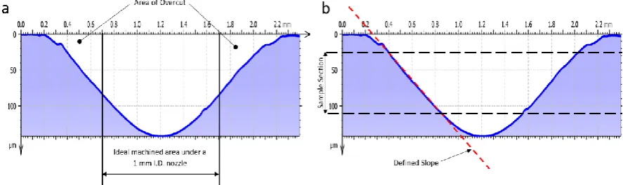
To assess the response profiles produced by the modified nozzles several metrics to help define the geometrical shape can be used. The resultant machined profiles of each nozzle type were imaged using a focus variation microscope (Alicona G5 infinite focus, x20 magnification) to create geometrical surface maps. Profiles of the resultant machined features were extracted from these surface maps using DigitalSurf MountainsMap software. Geometrical analysis of the profile data was carried out to obtain depth, width, area, overcut and side wall slope (taper) of each of the resultant profiles. Standard deviation (SD) is consistent across all results as the deviation from the mean taken over 30 individual samples.
Total overcut is defined in this investigation as the remaining area of the removed profile on both sides of the resultant feature. This is achieved by removing the ideal profile, being the area removed directly below the nozzle, for the full depth of the feature. In the case of Figure 5a this is 1 mm axially to the nozzle.
Overcut is undesirable in the EJP process and several alternative hybrid systems including laser assistance [46, 47], and electrochemical slurry jet micro-machining [48], have been proposed to reduce this. Minimising overcut is also seen as advantages within the process as not only does this demonstrate an increase in fidelity of the response profile to that expected, but also makes the process more easily implemented from design for manufacture
[image:14.595.80.524.433.565.2]perspective. Slope (Figure 5b) is defined in this case as the gradient of the side wall in rise over run format. Side wall taper was extracted from the bulk of the edge ignoring both the radius at the top and bottom of the wall. The mean of the two side-wall slopes is used for the slope angle of that profile. This is analogous to the taper defined in machining process and allows assessment between the profiles that are created and traditional tooling, greater slope giving a more uniform squarer cross section and a lower slope value giving a more triangulated profile.
Experimentation was carried out using a previously developed CNC EJP platform (Figure 8) built by the investigators, details of which can be found elsewhere [45]. Inconel 718 was the workpiece used in all experiments. It was chosen as the target demonstrator material for this process as it is applied in several high value sectors and it reliably demonstrates high and low current density effects on the resultant surface finish.
All samples were pre-polished to ≈ 1 µm surface roughness (𝑅𝑎) before machining. Samples
were cleaned post-process in an ultrasonic bath and swabbed with acetone before inspection.
Machining samples were created by carrying out striations across the workpiece surface with the nozzle orientation set by fixture to create the desired profile as denoted in the simulation. Repeated passes were carried out in separate striations passing over the same toolpath consecutively, increasing passes by one per striation (up to four).
[image:16.595.168.427.202.410.2]During experimentation, the electrolyte jet velocity for the 1 mm I.D. nozzle was set at 13 m/s for the initial experimental validation and 16 m/s in all other cases. For the 0.5 mm I.D. nozzle 16 m/s was used except for the form variation due to jet speed is experiments where jet speed was varied from 3 m/s to 25 m/s. For the 0.25 mm I.D. nozzle 16 m/s was used in all cases. The electrolyte used throughout was a 2.3 M solution of NaNO3. Analytical grade reagents
and deionised water were used. Electrolytes were maintained at 21°C during all experiments. Nozzle tip stand-off from the workpiece, in all cases, was initially set at 0.25 mm. A constant applied current was set at 900 mA (J =100 A/cm2) for 1 mm nozzle, 210 mA (J = 100 A/cm2)
for the 0.5 mm nozzle, except during parameter variation where it ranged from 80 A/cm2 to
200 A/cm2 and 100 mA (J = 200 A/cm2) for the 0.25 mm nozzle. Voltage was left to float as
this was seen to vary dependant on the nozzle geometry and subsequent resistance. Each pass was carried out at 0.5 mm/s translation speed for all work except for Figures 17, 18 and 20 (for 1 striation) where the translation speed was reduced to 0.1 mm/s.
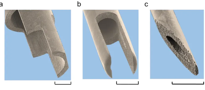
Standardised stainless steel, cylindrical, straight walled nozzles were used as the control and the base for the modified nozzle tip geometries. The patterns were generated in CAD and toolpaths generated in CAM. Using wire electrical discharge machining (WEDM), the modified geometry was cut into the standard nozzle tips (Figures 9, 10 and 11).
[image:17.595.81.525.432.565.2]The initial planar design nozzle contours were designed to be counter-intuitive to the known current density distribution found with a cylindrical nozzle (Figure 1b). Using 1 mm I.D. nozzles, these were tested to demonstrate the resultant profile could be modified by simply moving the focal point of the current density distribution. These rudimentary designs are
Figure 9: Tinted SEM images showing the standard and modified nozzles using a simple planar approach prepared by wire EDM. (a) Standard nozzle, (b) centre point element (CPE), (c) symmetrical twin element
referred to as (Figure 9b) centre point element (CPE), (Figure 9c) symmetrical twin element (STE) and (Figure 9d) off-centre single point element (OSPE).
Free form nozzles (Figure 10) were designed and tested again using 1 mm I.D. nozzles. This was carried out with consideration to the area of the elements of the nozzle tip contour and their position. The resultant profiles were analysed to assess the influence the changing area of each nozzle tip element, the nozzle as a whole and the resistance characteristics of the nozzle. These are referred to as the wide castellated nozzle (WC) (Figure 10a) and the narrow castellated nozzle (NC) (Figure 10b).
[image:18.595.159.448.328.482.2]The nozzles in Figure 11 were machined to experimentally assess the fidelity achievable between nozzle shape and resultant profile with respect to the DIF of the individual nozzle features and the scalability of the process. Figure 11a shows not only individual steps machined into the section to give three different resistance points but also the side wall of the nozzle is thinned therefore reducing the circumference and area at a localised section. Figure 11b copies the STE design from previous design except scaled and cut into a 500 μm I.D. nozzle and Figure 11c uses a scaled version of the OSPE design on a 250 μm I.D. nozzle. Using these smaller nozzles will show experimentally if the energy modulation translates to a
smaller scale when reducing distances between nozzle features and the hydrodynamic effects found in a more constrained nozzle.
3. Results and Discussion
3.1. Validation of nozzle design and simulation
Considering the electrolyte jet as a simplified resistor, the total current delivered is similar in all nozzle types, but the distribution is modified as a result of the nozzle geometry. This is demonstrated by the area of material removed in the resultant profiles, seen in Figure 12a and 12b being within a 3.5% deviation of the mean resultant profile area of 39000 µm2 the variation
coming from the varying DIF of each nozzle.
[image:19.595.94.513.166.350.2]The OSPE nozzle exhibits the deepest cut at 50 µm (SD <1%) compared to the standard nozzle generating only a 35 µm (SD <1%) deep cut. The STE design shows a cut depth just over half that of the OSPE nozzle at 28 µm (SD <1%) at the tip location of each feature. Along with the obvious form changes in the resultant profile (Figure 12b), there are also more subtle
Figure 11: Nozzle designs realised to evaluate the effectiveness of the DIF and scalability of the process (a) steps with a 1mm I.D. nozzle, (b) STE design with a 0.5mm I.D. nozzle and (c) OSPE design with a 0.25mm
changes. The overcut area of the STE nozzle beyond the ideal column below the nozzle is increased from 9300 µm2 (SD 7%) in the standard resultant profile to 10100 µm2 (SD 7%) for
the STE resultant profile. However, the side walls demonstrate an increase of 19% in slope, (83.6 µm/mm (SD <1%) as compared to 70.4 µm/mm (SD 4%) of the standard profile) due to the floor of the profile being wider as the current focuses under the twin elements at the edge of the jet. In comparison, the CPE resultant profile displays a side wall slope of 53.8 µm/mm (SD 3%) as the current profile is concentrated to the centre of the jet.
From Figure 12a discrete surface point simulation results (shown in red) exhibit good agreement in the cases of the standard, CPE and OSPE resultant profiles (shown in black) achieved after a single pass. The two-dimensional profile simulations were generated using the probability of dissolution of each element under the jet. This considers the applied current at that point (Figure 2b), the electrolyte current efficiency, known material constants and jet interaction availability for each element at the surface. For the standard nozzle profile, the simulation shows an area removal of 39200 µm2. This can be compared to the actual response
profile of 39100 µm2 (SD <1%) removed by the standard nozzle showing a variance of 0.2% Figure 12: (a) Example resultant machined profiles from a single pass (black line) and compared to the simulation
[image:20.595.82.538.279.466.2]simulation to actual. However, the standard response profile is marked by an increased removal observed at the bottom corners of the cut. This is likely due to hydrodynamic effects and a modified ejection path as dissolution advances. This ejection profile phenomena has been previously noted to occur during machining [42] utilising a cylindrical nozzle. For the CPE, STE and OSPE nozzles it demonstrates a mean variation of 4.8 % from simulation to actual. In the case of the CPE, electrolyte ejection from the cut is facilitated by the nozzle geometry and the cut profile, contrasting effects seen in the other nozzles. This permits a more accurate simulation. Jet ejection at the nozzle is not observed to change significantly but interaction and ejection from the machined feature does. Jet-rebounding effects causing re-machining [42] have been reported, however, given the edge effect upon the fluid flow regime, this phenomenon is proposed not to contribute significantly here.
[image:21.595.88.522.443.680.2]The CPE nozzle shows a maintained focus of the current density profile to the centre of the feature is due to the spacing of the nozzle rim contour to workpiece. Thus, a high resistance at the periphery of the jet is maintained regardless of the evolving surface profile (Figure 13b)
Figure 13: Extracted surface and profile from areal scans showing comparison of evolving response profile over four passes of (a) standard nozzle and (b) CPE nozzle demonstrating little change to the profile shape
The STE nozzle response profile differs whereby the simulation shows a variation in form with a higher peak in the centre of the cut. The actual cross-sectional area removed being 36700 µm2 (SD <1%) giving an 8 % variation from the theoretical value. This variation can be
[image:22.595.74.518.381.638.2]emulated to a degree by simulation of the electrical field effect occurring during machining and highlights the evolution of the cut profile. However, in this case the nozzle design is detrimental to the fidelity of the response profile to nozzle geometry. In Figure 14a, surface scans of striations cut with an STE nozzle over 4 passes demonstrate how the geometry develops for a typical surface feature. The depth increases from 28.6 µm (SD <1%) in a single pass to 112 µm (SD <1%) after four passes. While the depth increases the bottom of the profile flattens and taper decreases with a slope of 83.6 µm / mm (SD <1%) after 1 pass to 274 µm / mm (SD 2.4%) after 4 passes.
the centre of the jet. (e) showing the distance of the main element tips to a variable surface having become equal across the entire jet (f) With increasing passes the shorter path length is now to the central feature so
shifts machining focus
Considering Figure 14b, the electrical field effect is simulated for the initial pass against the flat surface by applying Equation 9 for electrical field strength.
Electrical field strength𝐸(𝑟) = 1
4𝜋𝜀0𝜀𝑟∫ 𝑑𝑟
′𝜌 𝑄(𝑟′)
𝑟−𝑟′
|𝑟−𝑟′|3
[9]
Where
𝜀
0𝜀
𝑟 is the electrolyte permittivity, 𝜌𝑄 is charge density r is the position of the point at which the electric field is calculated and r' is the location of the charge.maintaining the profile. It can be postulated that at this point hydrodynamic effects now start to affect the profile. Due to the rising centre feature, the stagnation point at the centre of the jet is now exacerbated. The impinging jet is forced either side of the central feature into the base of the valley where effectively a longer interaction is seen at the surface. Therefore, removal at the valley floor is increased and subtle deepening of the valleys occurs taking the distance to the nozzle tips out of equilibrium at discreet points. On a successive pass (Figure 14f), the distance to the interaction surface directly under the nozzle tips is now longer than that to the central feature giving a more favourable point for initial current attachment. Therefore, preferential machining takes place with a further shift in the primary machining zone to remove the central feature leaving a flat base to the profile. This result has been reported elsewhere [47], albeit due to polarisation effects masking areas of the profile which do not occur in this material. This aims to not only demonstrate the flexibility achievable with these modified nozzles but also that EJP can be self-limiting with appropriate nozzle and fluid dynamic considerations.
Freeform modification of nozzles in multiple planes were then undertaken. Wide castellation (WC) and narrow castellation (NC) nozzles are shown in Figure 15. The machined profiles were compared to the resultant STE profile in Figure 15a over a single pass. Marked changes to the profile can be seen from the profile scans, the WC profile showing a wider profile with a more pronounced double apex than the STE profile (exhibiting a side wall slope of 62.3 µm / mm (SD 2%) compared to 83.6 µm / mm (SD <1%)). The NC nozzle demonstrates superior geometric enhancement with a height increase of the central feature of 168% (SD 22%, the high deviation likely due to varying hydrodynamic effects) over the STE created profile and a reduction of 65% in the side wall taper with a slope of 187 µm / mm (SD 4.4%).
This is apparent when considering the resultant profiles from the NC and WC nozzles. The area of the four element tips in the NC nozzle being 125000 µm2 when compared to the WC
design having an element tip area of 64000 µm2. This gives a DIF for the NC nozzle elements
of 0.13 compared to the WC nozzle which has a DIF of 0.06. When considering the complete tip contour of all facing surfaces at the varying distances from the surface the DIF for the WC nozzle is 0.14 compared to the DIF of the NC nozzle being 0.42.
[image:25.595.81.515.72.252.2]When considering figure 16 showing the profile of the NC nozzle over increasing passes the geometry can be seen to again evolve in a similar fashion to that of the STE nozzle (Figure 16 a) and in contrast to that of the standard or CPE nozzle resultant profiles (Figure 13). This type of internal geometry can be considered as not being consistent across the range of surface energy delivered and so are prone to a high degree of variation dependant on process parameters and therefore consideration of this must be taken into account when developing
the desired geometry. In the case of the NC nozzle the central feature is still noticeable after four passes due to its greater prominence in the initial passes from the very defined current density profile.
[image:26.595.189.407.156.363.2]Figure 17 demonstrates the capability of these nozzles to achieve patterns with complex profiles and interactions which are simplistically and efficiently created with a one step process in a difficult material to competitively machine by other means over large areas. The array of features demonstrated also exhibits the flexibility of this process. STE and OSPE nozzles were used in combination. OSPE nozzles were first used at 0.1 mm/s feed, cutting the block in the Y direction over a single pass (Figure 17 e,f). Using the STE nozzle cuts were then made in the X direction to intersect the first two cuts (17 f,g) being single passes at 0.1 mm/s, the third cut being four passes over the same direction with constant parameters resulting in a much deeper cut (≈ 600 μm).It can be observed, the loss of the distinctive ‘W’ shape with multiple passes generating a flatter valley bottom as noted previously (Figure 17b) and the ramping in of the features created in the NC program to avoid key-holing and unstable processing conditions. The shallower features created in the x direction are formed by a bouncing type tool path with alternating start points at 0.5 mm/s (Figure 17 b,c,d). Additionally, the positional
repeatability demonstrated in previous work [49] is apparent alongside the ramping in and out of the features. Also, shallower features are observed where the substrate has changed thickness and the stand-off distance has become drastically reduced.
Figure 17: Inconel 718 machined by a selection of nozzles. (a) 3D surface generated from areal scan. (b,c,d,e,f,g) Tinted SEM images extracts of the machined piece demonstrating the range of surfaces that these
nozzle designs can create. All scale bars are 500 µm
centre of the features where energy density is higher [50]. In contrast, Figure 18, alternative finishes are achieved by the use of a higher jet speed, current density and slower traverse speed leading to greater edge definition, greater variation in surface texture and deeper cuts due to the changing dissolution mechanisms.
Figure 18: SEM images of machine features with an STE nozzle with a modified parameter set to produce different micro-texturing finishes (a) straight cut striation with increased current density and increased jet velocity (b) pocket intersecting a straight cut striation with increased jet velocity but lower traverse speed
giving a rougher surface finish. All scale bars are 500 µm
3.2. Process fidelity and scalability
highest step has been minimised. The area of the first step would need to be greatly reduced for greater distinction between the steps in the resultant profile.
When compared to the OSPE nozzle design from section 3.1 which has a simple design with graduation of decreasing DIF across the nozzle, so reflected in a linear graduation of the response profile away from the longest nozzle edge. Alternatively, when this is compared to the response profile of the steps nozzle this gives a curved effect away from the deepest part of the profile due to the sudden and stepped changes in the DIF
It is worthy of note the reduced kerf, being under the expected minimum of twice the nozzle I.D. [39, 45] (1.64 mm SD 3.5% ) which is found with the similar designed 1 mm I.D. OSPE nozzle (2 mm SD <1%). Also, the sharper intersection with the un-machined surface to the right of the profile. When comparing the distance from the deepest part of the valley to the dissolution interface with the unchanged surface, the steps nozzle measures a mean of 292 μm (SD 6%), compared to the OSPE nozzle measuring 507 μm (SD 3%) resulting in a 152% increase in side-wall steepness (219 μm / mm SD 6% to 551 μm / mm SD 6%). This is due to the thinning of the outside wall at this point on the nozzle giving a sudden increase in
Figure 19: Comparison of extracted machined resultant profiles compared to the simulated profile from the DIF equation (a) 0.25 mm I.D. OSPE nozzle. (b) 0.5 mm STE nozzle and (c) 1
resistance aiding ejection by limiting rebound effects [42] therefore limiting the spread of dissolution. The 500 μm STE nozzle (Figure 19b) shows the characteristic “W” shape usually associated with this design of nozzle. Even though the horizontal distance between the nozzle tips is reduced the twin valleys of the resultant profile remain, albeit at a much closer proximity, giving a sharper apex to the central feature.
Similarly, for the 250 μm OSPE nozzle (Figure 19a) the resultant profile also remains consistent with that that observed with the 1 mm I.D. OSPE nozzle demonstrating accurate scalability traits across both 500 μm I.D. and 250 μm nozzles with the designs tested throughout the range of the sizes.
[image:30.595.88.526.211.382.2]As the 500 μm STE nozzle was shown to maintain the expected profile further tests were carried out across multiple samples. Due to the reduced diameter of the nozzle a higher degree of variation could be obtained within the apparatus for current density and electrolyte jet speed (Figure 21) therefore the impact of parameter variation on the profile geometry could be assessed.
Figure 20:Example images samples features machined using the steps nozzles generated from areal surface scans showing single pass (shallowest cut) through 2, 3 and 4 passes with the final deepest groove being
Figure 21: Variation of machining parameters with a 0.5 mm I.D. nozzle (a) variation of current density (b) variation of Jet speed
Figure 21a shows the multiple striations machined in single passes with increasing current density. As expected, in line with prior work, as current density increases so the material removal and therefore depth increases. However, the ‘W’ shape is maintained throughout only increasing in definition due to the localised peaks in current density increasing and overcoming any polarisation effects. This is contrast to the repeating passes due to the jet being impinged on an un-machined surface so the focal point of the current density profile is unchanged. Figure 21b shows the effect of increasing electrolyte jet speed. It is worthy of note that it is only possible to create mask-less defined machining at the low speeds where the thin film area around the jet impingement area would not normally occur, due to the high pressure and design of the coaxial air shroud. Only at 3 m/s and 8 m/s is there a noticeable difference in volume removal due polarisation effects such as removal of oxide films formed which inhibits the current density peaks and effectively evens out the current density curve. Machined at 100 A/cm2 the expectant profile is generated in all cases with little variation in the side walls slope.
4. Conclusions
It was hypothesised that in-jet resistance could be locally altered by modifications to the nozzle tip geometry in order to develop the process capability of EJP. It has been clearly demonstrated that the manipulation of physical properties of the jet zone can change the response profile allowing significant advances over the state-of-the-art.
Through geometric modification of the nozzle apertures, altering the localised distance between nozzle and the opposite interaction surface at discrete points, the resistance was altered across the jet.
This was demonstrated firstly, using simplistic 2D simulations using known dissolution predictions of a dissolving surface incorporating the modulation of current density. This demonstrated that the resultant profile was found to be variable from that of a standard nozzle through a variety of simple tip designs.
Secondly, through experimental application of the nozzle designs, the simulation results were verified and when evaluated a 4.8% mean variation was found from simulation to actual. It was suggested that hydrodynamic ejection effects dominate causation for this.
The design impact factor (DIF) was introduced to enable the assessment of the design of nozzle tip elements, both in the area of the tip contour facing the incident surface and its distance. Freeform nozzle tip designs were specifically used to prove the validity of the DIF equation allowing modulation of the energy density field within the jet to allow response profile flexibility.
Jet speed and dwell time were found to have a large influence on the fidelity of the resultant profile especially when considering profiles with internal geometries. Further investigation of this influence and that of other process parameters is required to progress this work.
Variation in in-jet resistance has been unequivocally demonstrated and the mechanism elucidated. The results of this being the high degree of variation possible in the resulting machined profile. Coupling the results found here in this initial investigation with more mathematically-complex, multiphysics approach combining fluid mechanics of established processing models will allow a greater degree of process control and form prediction. Thus, allowing electrochemical jetting techniques to realise process maturity and be considered flexible, precise and sufficiently economic to be considered viable for the creation of high throughput biomimetic type surface structures. It can also be considered as a viable alternative to conventional shear-based processes in appropriate circumstances. Advances made here will facilitate cross-disciplinary collaboration with biologists, tribologists and advanced application component designers to realise next-generation, surface-critical components.
Acknowledgements
This work was supported by the Engineering and Physical Sciences Research Council [grant numbers EP/M02072X/1, EP/L016206/1] through the “In-Jet Interferometry for Ultra Precise Electrolyte Jet Machining” project, and through the EPSRC Centre for Doctoral Training in Innovative Metal Processing. The authors would like to thank The Manufacturing Metrology Team at the University of Nottingham for allowing access to the metrology equipment for surface scanning, Jeremy Straw of the Precision Manufacturing Centre (PMC) at the University of Nottingham for manufacture of the nozzles and Matthias Hirsch and Alexander Jackson-Crisp of ACEL for technical assistance with surface scanning.
References
[2] A. Malshe, K. Rajurkar, A. Samant, H.N. Hansen, S. Bapat, W. Jiang, Bio-inspired functional surfaces for advanced applications, CIRP Annals - Manufacturing Technology, 62 (2013) 607-628.
[3] A.A.G. Bruzzone, H.L. Costa, P.M. Lonardo, D.A. Lucca, Advances in engineered surfaces for functional performance, CIRP Annals - Manufacturing Technology, 57 (2008) 750-769. [4] B. Bhushan, Y.C. Jung, Natural and biomimetic artificial surfaces for superhydrophobicity, self-cleaning, low adhesion, and drag reduction, Progress in Materials Science, 56 (2011) 1-108.
[5] K. Liu, L. Jiang, Bio-inspired design of multiscale structures for function integration, Nano Today, 6 (2011) 155-175.
[6] M. Geetha, A.K. Singh, R. Asokamani, A.K. Gogia, Ti based biomaterials, the ultimate choice for orthopaedic implants – A review, Progress in Materials Science, 54 (2009) 397-425. [7] A.A. Valencia-Lazcano, T. Alonso-Rasgado, A. Bayat, Characterisation of breast implant surfaces and correlation with fibroblast adhesion, Journal of the mechanical behavior of biomedical materials, 21 (2013) 133-148.
[8] F. Zhang, J. Chan, H.Y. Low, Biomimetic, hierarchical structures on polymer surfaces by sequential imprinting, Applied Surface Science, 254 (2008) 2975-2979.
[9] H.N. Hansen, R.J. Hocken, G. Tosello, Replication of micro and nano surface geometries, CIRP Annals - Manufacturing Technology, 60 (2011) 695-714.
[10] M. Martínez-Calderon, A. Rodríguez, A. Dias-Ponte, M.C. Morant-Miñana, M. Gómez-Aranzadi, S.M. Olaizola, Femtosecond laser fabrication of highly hydrophobic stainless steel surface with hierarchical structures fabricated by combining ordered microstructures and LIPSS, Applied Surface Science.
[11] E. Azaceta, N.T. Tuyen, D.F. Pickup, C. Rogero, J.E. Ortega, O. Miguel, H.-J. Grande, R. Tena-Zaera, One-step wet chemical deposition of NiO from the electrochemical reduction of nitrates in ionic liquid based electrolytes, Electrochimica Acta, 96 (2013) 261-267.
[12] B. Denkena, J. Köhler, B. Wang, Manufacturing of functional riblet structures by profile grinding, CIRP Journal of Manufacturing Science and Technology, 3 (2010) 14-26.
[13] M. Kunieda, Influence of Micro Indents Formed by Electro-chemical Jet Machining on Rolling Bearing Fatigue Life, ASM, PED, 1993, 64 (1993) 693-699.
[14] M.M. Hackert, G. Schubert, A., Fast Micro Structuring with Electrolyte Jet Machining, in: Proceedings of Fourth International Symposium on Electrochemical Machining Technology, Fraunhofer, Chemnitz, 2007, pp. 123-128.
[15] W. Natsu, T. Ikeda, M. Kunieda, Generating complicated surface with electrolyte jet machining, Precision Engineering, 31 (2007) 33-39.
[16] C.B.D. Bocking, S.l, Bennett, G., , An investigation into the suitability ofhigh speed selective jet electrodeposition for rapid tooling, in: First National Conference on Rapid Prototyping and Tooling Research, MEP, 1995, pp. 157-173.
[17] M. Kunieda, R. Katoh, Y. Mori, Rapid Prototyping by Selective Electrodeposition Using Electrolyte Jet, CIRP Annals - Manufacturing Technology, 47 (1998) 161-164.
[18] N.J. Goffin, R.L. Higginson, J.R. Tyrer, The use of holographic optical elements (HOE's) to investigate the use of a flat irradiance profile in the control of heat absorption in wire-fed laser cladding, Journal of Materials Processing Technology, 220 (2015) 191-201.
[19] A. Kaur, C. Ribton, W. Balachandaran, Electron beam characterisation methods and devices for welding equipment, Journal of Materials Processing Technology, 221 (2015) 225-232.
[20] A. Chillman, M. Hashish, M. Ramulu, Energy Based Modeling of Ultra High-Pressure Waterjet Surface Preparation Processes, Journal of Pressure Vessel Technology, 133 (2011) 061205.
[23] H.-Y. Kim, J.-W. Yoon, W.-S. Choi, K.-R. Kim, S.-H. Cho, Ablation depth control with 40 nm resolution on ITO thin films using a square, flat top beam shaped femtosecond NIR laser, Optics and Lasers in Engineering, 84 (2016) 44-50.
[24] X. Yang, X. Liu, Y. Lu, S. Zhou, M. Gao, J. Song, W. Xu, Controlling the Adhesion of Superhydrophobic Surfaces Using Electrolyte Jet Machining Techniques, Scientific reports, 6 (2016) 23985.
[25] P.L. Torrubia, J. Billingham, D.A. Axinte, Stochastic simplified modelling of abrasive waterjet footprints, Proceedings. Mathematical, physical, and engineering sciences, 472 (2016) 20150836.
[26] M.C. Kong, S. Anwar, J. Billingham, D.A. Axinte, Mathematical modelling of abrasive waterjet footprints for arbitrarily moving jets: Part I—single straight paths, International Journal of Machine Tools and Manufacture, 53 (2012) 58-68.
[27] J. Billingham, C.B. Miron, D.A. Axinte, M.C. Kong, Mathematical modelling of abrasive waterjet footprints for arbitrarily moving jets: Part II—Overlapped single and multiple straight paths, International Journal of Machine Tools and Manufacture, 68 (2013) 30-39.
[28] A. Bilbao Guillerna, D. Axinte, J. Billingham, The linear inverse problem in energy beam processing with an application to abrasive waterjet machining, International Journal of Machine Tools and Manufacture, 99 (2015) 34-42.
[29] P.J. Slikkerveer, F.H.i.t. Veld, Model for patterned erosion, Wear, 233–235 (1999) 377-386.
[30] M. Ali, R. Henda, Modeling of beam-target interaction during pulsed electron beam ablation of graphite: Case of melting, Applied Surface Science, 396 (2017) 67-77.
[31] P. Parandoush, A. Hossain, A review of modeling and simulation of laser beam machining, International Journal of Machine Tools and Manufacture, 85 (2014) 135-145.
[32] G.B.J. Cadot, D.A. Axinte, J. Billingham, Continuous trench, pulsed laser ablation for micro-machining applications, International Journal of Machine Tools and Manufacture, 107 (2016) 8-20.
[33] A. Beaucamp, Y. Namba, R. Freeman, Dynamic multiphase modeling and optimization of fluid jet polishing process, CIRP Annals - Manufacturing Technology, 61 (2012) 315-318. [34] Z.-C. Cao, C.F. Cheung, Theoretical modelling and analysis of the material removal characteristics in fluid jet polishing, International Journal of Mechanical Sciences, 89 (2014) 158-166.
[35] K.M. Yoneda. Koji, Processing shape simulation in the electrolytic solution jet machining, Electrical Processing Journal, 29 (1995) 8.
[36] T. Ikeda, W. Natsu, M. Kunieda, Electrolyte Jet Machining Using Multiple Nozzles, IJEM, 11 (2006) 7.
[37] M.S. Rajput, P.M. Pandey, S. Jha, Modelling of high speed selective jet electrodeposition process, Journal of Manufacturing Processes, 17 (2015) 98-107.
[38] J. Kozak, K.P. Rajurkar, R. Balkrishna, Study of Electrochemical Jet Machining Process, Journal of Manufacturing Science and Engineering, 118 (1996) 490-498.
[39] M.H. Andreas. Schubert, Gunnar. Meichsner, Simulating the Influence of the Nozzle Diameter on the Shape of Micro Geometries generated with Jet Electrochemical Machining, in: COMSOL Conference, Milan, 2009.
[40] M.H.e. al., Investigating the Influence of Dynamic Jet Shapes on the Jet Electrochemical Machining Process, in: COMSOL Conference, Paris, 2010.
[41] M. Hackert-Oschätzchen, R. Paul, M. Kowalick, A. Martin, G. Meichsner, A. Schubert, Multiphysics Simulation of the Material Removal in Jet Electrochemical Machining, Procedia CIRP, 31 (2015) 197-202.
[42] M. Hackert-Oschätzchen, R. Paul, A. Martin, G. Meichsner, N. Lehnert, A. Schubert, Study on the dynamic generation of the jet shape in Jet Electrochemical Machining, Journal of Materials Processing Technology, 223 (2015) 240-251.
[44] W. Natsu, S. Ooshiro, M. Kunieda, Research on generation of three-dimensional surface with micro-electrolyte jet machining, CIRP Journal of Manufacturing Science and Technology, 1 (2008) 27-34.
[45] J. Mitchell-Smith, J.W. Murray, A.T. Clare, M. Kunieda, Electrolyte Jet Machining for Surface Texturing of Inconel 718, in: D. Bahre, A. Rebschlager (Eds.) INSECT 2014, Saarbrucken, Germany, 2014, pp. 111-118.
[46] A.K.M. DeSilva, P.T. Pajak, D.K. Harrison, J.A. McGeough, Modelling and Experimental Investigation of Laser Assisted Jet Electrochemical Machining, CIRP Annals - Manufacturing Technology, 53 (2004) 179-182.
[47] P.T. Pajak, A.K.M. Desilva, D.K. Harrison, J.A. McGeough, Precision and efficiency of laser assisted jet electrochemical machining, Precision Engineering, 30 (2006) 288-298. [48] Z. Liu, H. Nouraei, M. Papini, J.K. Spelt, Abrasive enhanced electrochemical slurry jet micro-machining: Comparative experiments and synergistic effects, Journal of Materials Processing Technology, 214 (2014) 1886-1894.
[49] J.C. Walker, T.J. Kamps, J.W. Lam, J. Mitchell-Smith, A.T. Clare, Tribological behaviour of an electrochemical jet machined textured Al-Si automotive cylinder liner material, Wear, (2017).
![Figure 3: A flow chart of the stochastic simulation process as described in the text. If a surface element is exposed and the probability of removal is greater than a random number, r∈[0,1], then the element will be dissolved](https://thumb-us.123doks.com/thumbv2/123dok_us/8578075.369422/10.595.191.389.74.408/stochastic-simulation-described-exposed-probability-greater-element-dissolved.webp)