Incorporation and Evolution of ZrO2 Nano-particles in Pt-modified Aluminide Coating
for High Temperature Applications
Lingyi Qian1, Fang Xu1, K.T. Voisey1, Vahid Nekouie2, Zhaoxia Zhou3, Vadim V. Silberschmidt2, Xianghui Hou1*
1Faculty of Engineering, University of Nottingham, Nottingham, NG7 2RD, UK
2Wolfson School of Mechanical, Electrical and Manufacturing Engineering, Loughborough
University, Leicestershire, UK
3 Loughborough Materials Characterisation Centre, Department of Materials, Loughborough
University, Leicestershire, UK
*Corresponding Author, Email: [email protected] Tel: +44 115 95 13920, Fax: +44 115 95 13800
Abstract
providing better understanding of reactions of ZrO2 and the influence of the substrate on bond coat behaviour.
1. Introduction
Platinum modified aluminide (PtAl) coating is widely used as a bond coat in thermal barrier coating (TBC) systems to fulfil high temperature requirements for turbine engine components [1,2]. The addition of Pt can improve the oxidation resistance and stability of aluminide coatings [3,4]. Thermally grown oxide (TGO) formed in service can cause degradation of PtAl coatings via Al depletion [5]. Rumpling of bond coats caused by martensitic transformation of β-NiAl phase due to Al depletion can result in top coat delamination and TBC failure [6–8]. Hence, rumpling resistance is one of the important factors relating to improving thermal cyclic lifetime of thermal barrier coatings with PtAl coatings.
Reactive elements have been reported to enhance TGO adhesion and reduce the TGO growth rate [9–13]. According to dynamic segregation theory, reactive elements can form oxides at the TGO/bond coat interface, and these oxide pegs increase the bonding strength of TGO [14]. In addition, the oxides of reactive elements have been proposed to slow down the outward diffusion of Al and change the TGO growth mechanism to predominantly inward diffusion of oxygen, which can further reduce the TGO growth rate [14–16]. As one of the reactive elements, Zr demonstrated its great ability to improve oxidation resistance and enhance TGO adhesion to aluminide coatings [16–18]. However, the investigation of Zr was mostly limited to alloys rather than coatings [16,19]. To date, only limited studies have reported the effects of Zr in PtAl coatings [20,21], and it should be noted that the methods used for introducing Zr are either costly or under development [20,22].
Element Effects (REEs) via reactive element oxides have not been clearly established. The present work investigated the REEs by adding ZrO2 nanoparticles into PtAl coatings in order to improve thermal cycling performance. Incorporation of ZrO2 particles in Pt coating (Pt-ZrO2) was achieved by co-electrodeposition [23]. ZrO2 modified PtAl coatings (ZrO2-PtAl) were evaluated using thermal cyclic oxidation tests. The evolution of ZrO2 particles and their role in TGO growth were also discussed.
2. Experimental Procedure
2.1 Substrate Preparation
Mar-M-247 (Advanced Alloy Services Ltd.) was used as the main set of substrates, while Mar-M-246 (Select Alloys & Materials Ltd.) was employed to verify the influence of Hf on ZrO2 particles. In addition, Inconel 718 (Goodfellow) substrates were also prepared as reference substrates because this alloy contains neither Hf nor Zr. Chemical compositions of the substrates are shown in Tab. I. The substrates were machined into round pellets 15 mm in diameter and 2 mm thick. Grit blasting was carried out before coating preparation using 220 grit white alumina.
2.2 Preparation of ZrO2-modified PtAl Coatings
before undergoing diffusion heat treatment at 1100°C for 1 hour in a vacuum furnace (10-6 mbar). The aluminising process was then carried out: the samples were placed above an aluminising powder mixture (73 wt.% Al2O3, 15% wt.% Al and 2 wt.% NH4Cl) and heat treated at 1140°C for 1 hour in a 5%H2/95%Ar atmosphere. Finally, a post heat treatment was performed in a vacuum furnace (10-6 mbar) at 1100°C for 1 hour. Conventional Pt-modified aluminide (PtAl) coatings without additions of ZrO2 nano-particles were also prepared following the same procedure to act as a bench mark.
In addition, pure Al powder and ZrO2 particles were mixed and pressed into 20 mm diameter pellets to verify reactions between Al and ZrO2. Two different heat treatments were applied to investigate the reactions under the different environments which had been used to prepare PtAl coatings: (1) pellets of 1.5 g Al and 1.5 g ZrO2 were heat treated at 1100°C in vacuum (10-6 mbar); (2) pellets of 1.5 g Al and 0.5 g ZrO2 were heat treated at the same temperature in a controlled environment (5%H2/95%Ar). The high Al loading was deliberately chosen in order to study the effect of Al content on the reaction products.
2.3 Thermal Cyclic Oxidation
Thermal cyclic oxidation testing was performed with a rapid high temperature furnace (CM Inc. 1608 BL). Each thermal cycle included 10 min of heating up to 1100°C, a 1-hour dwell time at 1100°C and forced air cooling for 20 min. Coatings on Mar-M247 and Mar-M246 were tested for 50, 100 and 200 cycles, and those on Inconel 718 were tested for 50 and 200 cycles.
2.4 Characterisation
Abrasive Cut-off wheel. The cutting speed was set to 0.005 m/s in order to minimise damage to cross-sections of the coating. Conductive resin was used to mount the sectioned samples followed by grinding using P240, P400, P800 and P1200 sandpapers followed by polishing with diamond paste down to a particle size of 0.02 μm. A Philips XL 30 FEG-ESEM system was used to image the coatings and energy-dispersive X-ray spectroscopy (EDX, INCA, Oxford Instruments) was employed to analyse composition of the coatings. A Siemens D500 XRD operated at 25 mA and 40 kV was utilised to study phases of the Al-ZrO2 mixture after heat treatment. Cross sections of the ZrO2-PtAl electroplating layer on Mar-M-247 after oxidation were prepared for transmission electron microscopy (TEM) analysis using a focused ion beam microscope (FEI Nova Nanolab 600). Microstructure characterization of the cross-sections and composition mapping were performed using a FEI Tecnai F20 G2 S-Twin field emission gun (FEG) TEM. The TEM was operated at 200kV and equipped with an Oxford Instruments X-Max 80 mm2 TLE detector for energy dispersive X-ray (EDX) spectroscopy. Scanning TEM bright field images of the layer were also collected simultaneously with an electron probe diameter ~1 nm convergence semi-angle 10 mrad.
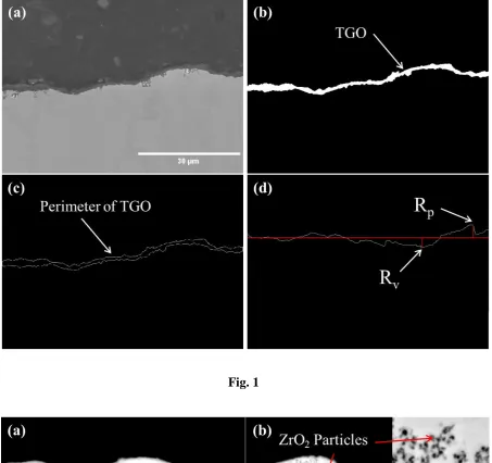
determined in order to calculate its area and length. The latter was calculated by simply dividing the length of the perimeter (after subtraction of short edges) by 2. The effective TGO thickness was determined by dividing the TGO area by the length of the TGO/substrate interface. For roughness calculation, only the top surface was used to assess the roughness profile of TGO. Since the locations of pixels in the perimeter were known, the average height of the TGO could be calculated and Rp (the height of the highest peak in the profile) and Rv (the depth of the deepest valley in the profile) then be determined (Fig. 1d). Rt, which is the sum of Rp and Rv (Rt = Rp + Rv), was utilised to evaluate the rumpling resistance of the prepared coatings.
3. Results
3.1 Microstructures of Pt-ZrO2 modified Aluminide Coatings
Prior to heat treatment and aluminising, the microstructure of the as-deposited Pt-ZrO2 coating was characterised. Backscattered electron (BSE) images of cross-sections of pure Pt coatings and the Pt-ZrO2 coating on Mar-M-247 are shown in Fig. 2. An enlarged image in Fig. 2 (b) shows the incorporated ZrO2 nano-particles with dimensions of 50-100 nm. With the same electroplating time, Pt-ZrO2 electroplating yielded a slightly thicker coating than was obtained for the pure Pt coating, which may be as a result of dispersed ZrO2 nano-particles enhancing the nucleation of Pt deposition.
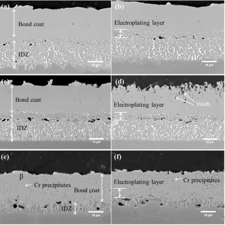
stages. Both PtAl and ZrO2-PtAl coatings had similar microstructures on Mar-M-247 and Mar-M-246, and the EDX results confirmed that β-(Ni,Pt)Al phase was formed predominately in the coating region. Refractory elements, such as W and Mo, were detected in the inter-diffusion zone (IDZ). This is attributed to previously noted effect of the inward diffusion of Al reducing the solubility of refractory elements in the Ni-base substrate [15]. The EDX analysis revealed the presence of Cr precipitates in both coatings on Inconel 718, attributed to the high concentration of Cr. The reduced IDZ on this substrate may be due to the low concentration of refractory elements.
3.2 Thermal Cyclic Oxidation
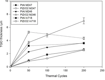
TGO thickness changes in the PtAl and ZrO2-PtAl coatings during the thermal cyclic oxidation test are summarised in Fig. 4 and Tab. II. There is an indication that TGO growth in the Mar-M-247 samples was slowed by the addition of ZrO2. However, increased TGO growth rates were observed in the ZrO2 modified coatings on both Mar-M-246 and Inconel 718. The decrease of TGO thickness in the ZrO2 modified coating on Inconel 718 was due to TGO spallation.
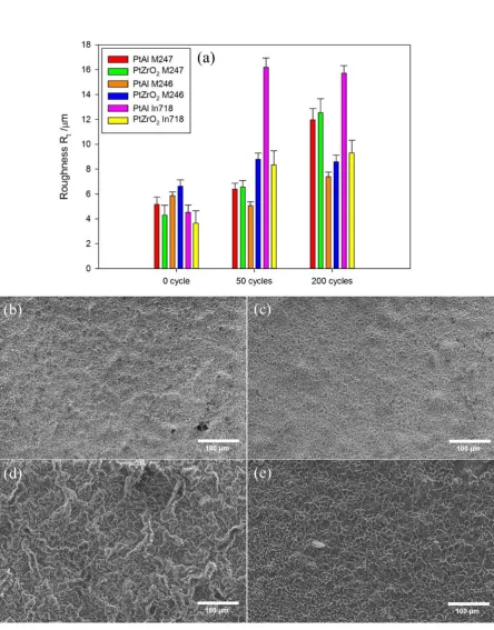
Fig. 5d. However, the rumpling of ZrO2-PtAl coating was not obvious after 50 cycles, as observed in Fig. 5c and Fig. 5e. There was no significant change in TGO roughness for either coating between 50 and 200 cycles, which may be due to the spallation of TGO after 200 cycles.
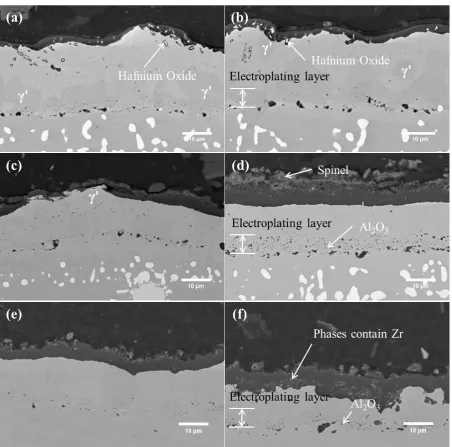
Fig. 6 reveals the microstructures of the PtAl and ZrO2-PtAl coatings after 200 oxidation cycles at 1100°C. The EDX analysis indicated that hafnium rich oxides were formed inside the TGO and the PtAl coating region in both coatings on Mar-M-247, shown in Fig. 6 (a) and (b). Most of the hafnium rich oxides observed in the ZrO2-PtAl coating contained Zr; this was rarely found in the PtAl coating. The EDX analysis also indicated the presence of γ' phase (Ni3Al) in both coatings. On Mar-M-246, a discontinuous TGO was found in the PtAl coating (Fig. 6c) and a spinel phase was formed on the top of TGO in the ZrO2-PtAl coating (Fig. 6d). The transformation from β to γ phase was completed in both coatings. The EDX analysis of the particles in the electroplating layer of ZrO2-PtAl coating on Mar-M-246 indicated them to be Al2O3 (Fig. 6d). Similar particles were also found in the ZrO2-PtAl coating on Inconel 718 (Fig. 6f) but were not observed in the ZrO2-PtAl coating on Mar-M-247 or any of the unmodified PtAl coatings. EDX also detected the presence of Zr in the bright phases within the TGO layer of the ZrO2-PtAl coating on Inconel 718.
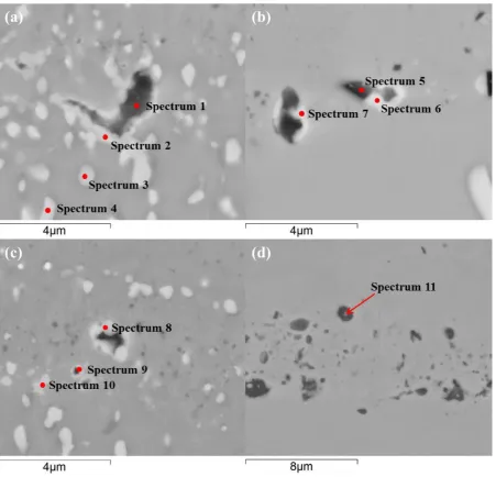
Zr was detected (Fig. 7c, spectra 8-10). For the Mar-M-246 substrate shown in Fig. 7 (d), no hafnium precipitate was formed in the electroplating layer, which is not surprising given that there was no Hf in Mar-M-246. Nevertheless, in the labelled location shown in Fig. 7 (d), a small amount of Zr was detected (spectrum 11). Because of the presence of Zr in both Mar-M-247 and Mar-M-246, it is difficult to verify whether the observed Zr came from the ZrO2 particles or the substrate. However, Inconel 718 does not contain Zr, so Zr found in the TGO layer on Inconel 718 can be confirmed as coming from the ZrO2 particles.
Fig. 8a shows a bright field scanning TEM image of a typical position in the ZrO2-PtAl electroplating layer on Mar-M-247 after 200 thermal cycles, Figs. 8b-8e are the corresponding maps of Al, O, Hf and Zr. Figs. 8b and 8c confirm that the detected Al2O3 particle size was less than 200 nm, similar to the original size of the incorporated ZrO2 particles. Fig. 8c indicates an area of lower oxygen concentration, as labelled. However, Fig. 8d reveals that Hf was slightly concentrated in the same locations as lower oxygen concentrations, surrounding the formed Al2O3. In addition, Al content was also relatively high in the Hf concentrated area. Because the indicated area was enriched with Al and Hf, it suggested formation of a HfAl solid solution around the Al2O3. However, because the Mar-M-247 substrate contains Zr, the source of the Zr seen in Fig. 8e could not be confirmed.
3.3 Reaction between Al and ZrO2 Particles at 1100°C
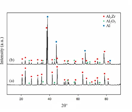
vacuum heat treatment to form Al3Zr. The XRD results for the heat treatment in the controlled environment (5%H2/95%Ar) with a higher Al/ZrO2 ratio again confirmed the formation of Al2O3 and Al3Zr (Fig. 9 Graph b).
4. Discussion
4.1 Mechanism of reactions on ZrO2 particles
An interesting phenomenon from the above investigation is the disappearance of the ZrO2 particles after heat treatment. Therefore, possible reaction mechanisms of ZrO2 particles are discussed to clarify the behaviour of ZrO2 in aluminide coatings.
4.1.1 Reactions between Al and ZrO2
The importance of aluminium has been highlighted in Section 3.3, confirming that aluminium and ZrO2 can react during the heat treatment. Still, the reaction between Al and ZrO2 mainly depends on the environment, such as very low-pressure oxygen or vacuum [25]. When in a vacuum or low-pressure oxygen environment, the reaction between Al and ZrO2 becomes thermal dynamically possible, as describe by Reaction (1) [25].
13Al + 3ZrO2 → 2Al2O3 + 3Al3Zr (1)
In Tremouilles’s work, only Al2O3 was observed at the interface between Al and ZrO2 [26]. Reaction (1) then can be written as follows [26]:
4Al3+ + 3ZrO2 → 2Al2O3 + 3Zr4+ (2)
The formed Zr4+ may be free to diffuse into the substrate and ready for diffusion in the subsequent oxidation period.
4.1.2 Effects of Hf on Al2O3
Formation of hafnium rich precipitates at the interface between the PtAl coating and the inter-diffusion zone on Mar-M-247 has not been widely reported [27]. They have a different formation mechanism compared to hafnium oxides formed inside the TGO layer [9], in which Hf was considered to react because of high oxygen reactivity. Hf was reported to react with Al2O3 [28]; the reaction is shown below:
7Hf + 2Al2O3 → 4HfAl +3HfO2 (3)
The presence of HfO2 is confirmed in the current experimental results for Mar-M-247, and evidence of the formation of HfAl was observed in Fig. 8b and 8d. Furthermore, the source of Al2O3 could be the embedded sandblasting alumina. It means that the hafnium rich precipitates formed in the PtAl coating may be a result of the interaction of hafnium with the sandblasting media. However, the reaction between Al and ZrO2 can also provide Al2O3 for the reaction. When reactions (2) and (3) are combined, i.e. Al2O3 formed in reaction (2) participates in reaction (3), the resultant reaction can be written as:
From reaction (4), it is suggested that the combination of reactions between Hf, Al and ZrO2 can form hafnium oxide, HfAl and Zr4+. This is consistent with the Zr identified in the hafnium rich precipitates found in the ZrO2-PtAl coating (spectrum 2) and the TEM characterisation shown in Fig. 8. Because of the direct reaction between Al2O3 and Hf, it can also form Hf-rich precipitates without Zr. In spectra 2 and 6, the Al contents are both much lower than expected. Decomposition of HfAl may occur after reaction (3). Al can dissolve in the substrate to form a solid solution with Ni because Hf forms a more stable oxide. Meanwhile, Zr4+ may partially dissolve in the coating substrate and also form oxides with Hf [16]. Even though the original Zr content in Mar-M-247 could affect the reactions of ZrO2 particles, the results on Inconel 718 confirmed the reaction between Al and ZrO2 particles and further diffusion of Zr in cyclic oxidation.
For the coatings on the Mar-M-246 substrate, neither hafnium rich oxides nor precipitates were formed, but Fig. 7 (d) revealed a Zr-containing phase in the centre of the aluminium phase. In addition, some Al2O3 particles were found in the particle regions on Mar-M-246 and Inconel 718, indicating that Hf can consume Al2O3 particles from the reaction between Al and ZrO2. Furthermore, hafnium-rich precipitates were commonly seen to have formed at the edges of Al2O3 particles.
4.1.3 Reaction mechanism of ZrO2 nano-particles in PtAl coating
was present, it could react with the outer alumina to form hafnium oxide and HfAl. Once the alumina was consumed, the residual ZrO2 could continue to react with Al. Because of the congener effect, Zr released from ZrO2 particles could form oxides and precipitates together with hafnium. In addition, some Hf and Al from HfAl may have a chance to dissolve into the substrate. Al can initiate the reaction with ZrO2 and release Zr4+. The effects of Hf were mainly to react with alumina to release Zr from the ZrO2 particles and form oxides or precipitates with Zr simultaneously. Other elements, such as Cr and W may affect the ZrO2 particles, but their influence was limited based on TEM characterisation, which will be clarified in future work.
Hafnium is further expected to be useful if the incorporated ZrO2 has a larger particle size. When the particle size is small (such as nano-particles), Al can complete the reaction with ZrO2 as it was seen in Fig. 6 (d). When the particle is large enough (such as micro-particles), the unreacted ZrO2 core is expected. In this situation, Hf can react with the Al2O3 shell formed and release Zr from ZrO2. However, the dispersion of large particles in the electrolyte is not desirable for co-electrodeposition. In this investigation, Mar-M-247 had 1.5 wt. % Hf, which was thought to be enough to react with Al2O3. However, an incomplete reaction with Al2O3 can be foreseen if there was not enough Hf in the substrate, resulting in unreacted ZrO2 particles. The sandblasting alumina is considered as harmful to oxidation resistance because it can consume Hf through the reaction between Hf and Al2O3.
finally released from ZrO2 particles and participated in oxidation because of the reactions with Al. However, the ZrO2 micro-particles were segregated at grain boundaries in a powder metallurgy fabricated ZrO2 strengthened NiAl/Cr(Mo, Hf) (33Ni–33Al–31Cr–2.8Mo–0.2Hf at.%) composite alloy instead of reacting with Al [29]. This may suggest that large ZrO2 particles may have different effects on the reaction between Al and ZrO2. Additional investigations should be carried out to study the behaviour of transition phases, such as Al3Zr and HfAl in the coating, in order to determine the diffusion mechanisms of Zr and Hf.
4.2 Effects of ZrO2 particles on oxidation behaviours of PtAl coating
roughness of the TGO.
It is also of interest to discuss the combined effects of Hf and Zr. Because Zr was detected in hafnium precipitates and the different features of ZrO2-PtAl coating were found on different substrates, the hafnium rich precipitates could act as a reservoir of Zr and slowly release Zr to the surface to help improve oxidation resistance. Once the interfacial oxide pegs are formed, the individual effect of Hf or Zr could be optimised by forming joint oxides to further retard the outward diffusion of Al and reduce the growth rate of TGO [16]. However, because Zr from the added ZrO2 particles was released by the reaction between Al and ZrO2, the effects of Zr from pure Zr addition and ZrO2 particles may be different. When pure Zr is incorporated by EB-PVD (electron beam physical vapour deposition) on a coating surface, the Zr-rich phase is formed after heat treatment and helps reduce the growth rate of TGO at early stages of oxidation [20]. However, Zr coming from ZrO2 particles, needs to diffuse first to the coating surface because ZrO2 particles are present inside the PtAl coating. A longer vacuum heat treatment of ZrO2-containing coating may achieve similar effects to addition of pure Zr to the surface. Nevertheless, the incorporation of ZrO2 nano-particles provides an alternative, possibly cost-effective method to achieve the advantages of Zr addition.
5. Conclusions
ZrO2 nano-particles were successfully incorporated into electrodeposited PtAl coatings by co-electrodeposition. Performance of the ZrO2-PtAl coatings was investigated through thermal cyclic oxidation on different substrates and the following conclusions can be drawn:
Inconel 718.
(ii) ZrO2 particles disappeared during both vacuum (10-6 mbar) and controlled environment (5%H2/95%Ar) heat treatment. The disappearance of the particles is because of the reaction with Al, proved with TEM characterisation. The reactions of the ZrO2 particles were observed to vary with substrate composition, and the presence of Hf plays an important role in the reaction.
(iii) When Al was present without Hf, ZrO2 particles disappeared through the reaction between Al, which could leave un-reacted ZrO2 in the coating. In the presence of Hf, the reaction could further release Zr and form a reservoir of Zr to help improve oxidation resistance. Synergistic actions of Zr and Hf were found to be better in improving the oxidation resistance.
(iv) Because of the reactions with Al and Hf, Zr was finally released from ZrO2 particles and helped to improve the rumpling resistance of the PtAl coating during thermal cyclic oxidation. The reaction mechanism of ZrO2 nano-particles provides a deeper understanding of the reactions of ZrO2 and the influence of substrate on bond coat compositions.
Acknowledgement
References
[1] D.J. Sordelet, M.F. Besser, R.T. Ott, B.J. Zimmerman, W.D. Porter, B. Gleeson, Isothermal nature of martensite formation in Pt-modified beta-NiAl alloys, Acta Mater. 55 (2007) 2433–2441. doi:10.1016/j.actamat.2006.11.038.
[2] R. Streiff, O. Cerclier, D.H. Boone, Structure and hot corrosion behavior of platinum-modified aluminide coatings, Surf. Coat. Technol. 32 (1987) 111–126. doi:10.1016/0257-8972(87)90101-0.
[3] H. Svensson, M. Christensen, P. Knutsson, G. Wahnstrom, K. Stiller, Influence of Pt on the metal-oxide interface during high temperature oxidation of NiAl bulk materials, Corros. Sci. 51 (2009) 539–546. doi:10.1016/j.corsci.2008.12.016.
[4] G.R. Krishna, D.K. Das, V. Singh, S. V Joshi, Role of Pt content in the microstructural development and oxidation performance of Pt-aluminide coatings produced using a high-activity aluminizing process, Mater. Sci. Eng.A 251 (1998) 40–47.
doi:10.1016/s0921-5093(98)00655-8.
[5] I. Spitsberg, K. More, Effect of thermally grown oxide (TGO) microstructure on the durability of TBCs with PtNiAl diffusion bond coats, Mater. Sci. Eng. A. 417 (2006) 322–333. doi:10.1016/j.msea.2005.11.014.
[6] M.W. Chen, M.L. Glynn, R.T. Ott, T.C. Hufnagel, K.J. Hemker, Characterization and modeling of a martensitic transformation in a platinum modified diffusion aluminide bond coat for thermal barrier coatings, Acta Mater. 51 (2003) 4279–4294.
doi:10.1016/S1359-6454(03)00255-6.
[7] Y. Zhang, J.A. Haynes, B.A. Pint, I.G. Wright, W.Y. Lee, Martensitic transformation in CVD NiAl and ( Ni , Pt ) Al bond coatings, Surf. Coat. Technol. 164 (2003) 19–24. [8] A.M. Karlsson, On the mechanical response in a thermal barrier system due to
martensitic phase transformation in the bond coat, J. Eng. Mater. Technol. 125 (2003) 346–352.
[9] R.W. Jackson, D.M. Lipkin, T.M. Pollock, Thermal barrier coating adherence to Hf-modified B2 NiAl bond coatings, Acta Mater. 80 (2014) 39–47.
doi:10.1016/j.actamat.2014.07.033.
[10] Q. Wu, H.M. Chan, J.M. Rickman, M.P. Harmer, J. Smialek, Effect of
Hf4+concentration on oxygen grain-boundary diffusion in alumina, J. Am. Ceram. Soc. 98 (2015) 3346–3351. doi:10.1111/jace.13762.
[11] L. Wei, H. Peng, F. Jia, L. Zheng, S. Gong, H. Guo, Cyclic oxidation behavior of Hf/Zr co-doped EB-PVD β-NiAl coatings at 1200°C, Surf. Coatings Technol. 276 (2015) 721–725. doi:10.1016/j.surfcoat.2015.05.039.
NiAl coatings at 1200 degrees C, Corros. Sci. 53 (2011) 2228–2232. doi:10.1016/j.corsci.2011.03.003.
[13] Y. Wang, J.L. Smialek, M. Suneson, N. Glenn, Oxidation behavior of Hf-modified aluminide coatings on Inconel- 718 at 1050 ° C, J. Coat. Sci. Technol. (2014) 25–45. [14] B.A. Pint, Experimental observations in support of the dynamic-segregation theory to
explain the reactive-element effect, Oxid. Met. 45 (1996) 1–37. doi:10.1007/bf01046818.
[15] S. Bose, High temperature coatings, Elsevier Butterworth-Heinemann, Amsterdam ; Boston, 2007. http://www.loc.gov/catdir/toc/ecip074/2006035922.html.
[16] H. Guo, D. Li, L. Zheng, S. Gong, H. Xu, Effect of co-doping of two reactive elements on alumina scale growth of β-NiAl at 1200°C, Corros. Sci. 88 (2014) 197–208.
doi:10.1016/j.corsci.2014.07.036.
[17] G.H. Hwang, J.W. Choi, S.G. Kang, The effect of zirconium on corrosion behavior of NiAl intermetallic compound in molten carbonate salt, Zeitschrift Fur Met. 96 (2005) 269–275. <Go to ISI>://WOS:000228395200008.
[18] K.S. Murphy, Pt-Al-Hf/Zr coating and method, US 2010/0297471 A1, 2010. [19] J.Y. Guédou, C. Tiwary, V. V Gunjal, D. Banerjee, K. Chattopadhyay, J. Choné,
Intermetallic eutectic alloys in the Ni-Al-Zr system with attractive high temperature properties, MATEC Web Conf. 14 (2014) 1005. doi:10.1051/matecconf/20141401005. [20] S.J. Hong, G.H. Hwang, W.K. Han, K.S. Lee, S.G. Kang, Effect of zirconium addition
on cyclic oxidation behavior of platinum-modified aluminide coating on nickel-based superalloy, Intermetallics. 18 (2010) 864–870. doi:10.1016/j.intermet.2009.12.012. [21] W.S. Walston, Coating and surface technologies for turbine arifoils, in: Superalloys,
TMS (The Minerals, Metals & Materials Society), 2004.
[22] S. Hamadi, M.P. Bacos, M. Poulain, A. Seyeux, V. Maurice, P. Marcus, Oxidation resistance of a Zr-doped NiAl coating thermochemically deposited on a nickel-based superalloy, Surf. Coatings Technol. 204 (2009) 756–760.
doi:10.1016/j.surfcoat.2009.09.073.
[23] R. Arghavanian, N. Parvini-ahmadi, The effect of co-electrodeposited ZrO 2 particles on the microstructure and corrosion resistance of Ni coatings, (2011) 2199–2204. doi:10.1007/s10008-010-1229-z.
[24] S.J. Hemsley, W. Zhou, Platinum plating for turbine blades: technology development and process improvement, Trans. Inst. Met. Finish. 88 (2010) 11–16.
doi:10.1179/174591909x12614816487692.
ISI>://WOS:000168657100013.
[26] G. Tremouilles, R. Portier, TEM study of ZrO2 / Al interface, J. Phys. Colloq. 49 (1988) 299–304.
[27] Y. Wang, M. Suneson, G. Sayre, Synthesis of Hf-modified aluminide coatings on Ni-base superalloys, Surf. Coatings Technol. 206 (2011) 1218–1228.
doi:10.1016/j.surfcoat.2011.08.031.
[28] X.A. Zhao Kolawa, E. and Nicolet, M. A., Reaction of thin metal films with crystalline and amorphous Al2O3, J. Vac. Sci. Technol. A (1986).
[29] L.Y. Sheng, J.T. Guo, T.F. Xi, B.C. Zhang, H.Q. Ye, ZrO2 strengthened
NiAl/Cr(Mo,Hf) composite fabricated by powder metallurgy, Prog. Nat. Sci. Mater. Int. 22 (2012) 231–236. doi:10.1016/j.pnsc.2012.04.003.
[30] J. Romanowska, M. Zagula-Yavorska, J. Sieniawski, Zirconium influence on microstructure of aluminide coatings deposited on nickel substrate by CVD method, Bull. Mater. Sci. 36 (2013) 1043–1048. doi:10.1007/s12034-013-0579-4.
[31] M. Zagula-Yavorska, M. Pytel, J. Romanowska, J. Sieniawski, The effect of Zirconium addition on the oxidation resistance of aluminide coatings, J. Mater. Eng. Perform. 24 (2015) 1614–1625. doi:10.1007/s11665-015-1421-5.
[32] B.A. Pint, The oxidation behavior of oxide-dispersed beta-NiAl: I. Short-term performance at 1200 degrees C, Oxid. Met. 49 (1998) 531–559.
doi:10.1023/a:1018894711276.
[33] B.A. Pint, I.G. Wright, W.Y. Lee, Y. Zhang, K. Prussner, K.B. Alexander, Substrate and bond coat compositions: factors affecting alumina scale adhesion, Mater. Sci. Eng. A. 245 (1998) 201–211. doi:10.1016/s0921-5093(97)00851-4.
Tables
Tab. I Chemical compositions of Mar-M-247, Mar-M-246 and Inconel 718.
Elements (wt. %)
C Cr Ni Co Mo W Ta Ti Al B Zr Hf Nb Fe
Mar-M-247 0.16 8.2 Bal. 10 0.6 10 3 1 5.5 0.015 0.05 1.5 - -
Mar-M-246 0.15 9 Bal. 10 2.5 10 1.5 1.5 5.5 0.015 0.05 - - -
Tab. II TGO thicknesses of PtAl and ZrO2-PtAl coatings on different substrates
TGO Thickness
(μm)
PtAl
Mar-M-247
ZrO2-PtAl
Mar-M-247
PtAl
Mar-M-246
ZrO2-PtAl
Mar-M-246
PtAl
Inconel 718
ZrO2-PtAl
Inconel 718
50 cycles 0.98 ± 0.04 0.85 ± 0.03 2.29 ± 0.04 3.71 ± 0.18 3.21 ± 0.13 5.28 ± 0.15
100 cycles 1.86 ± 0.13 1.28 ± 0.04 2.95 ± 0.03 4.81 ± 0.27 - -
Tab. III EDX results for locations labelled in Fig. 7.
Elements
(wt. %) O Cr Ni Co W Al Zr Hf Pt
Spectrum 1 32.7 3.0 15.7 3.2 - 14.0 4.8 18.4 -
Spectrum 2 22.8 - 7.1 - - 3 8.3 42.5 -
Spectrum 3 - 7.4 26.3 7.1 31.2 - - - 21.1
Spectrum 4 - 11.1 19.0 10.4 42.5 3.6 12.2 - -
Spectrum 5 20.3 3.5 33.0 4.1 - 16.4 - 8.2 13.0
Spectrum 6 20.3 1.5 12.2 1.8 - 3.0 12.1 48.9 -
Spectrum 7 3.6 4.3 40.9 5.0 - 11.9 - 7.7 26.2
Spectrum 8 13.9 1.7 13.0 2.1 - 3.4 - 53.4 12.6
Spectrum 9 9.9 2.2 17.9 2.8 - 5.7 - 43.4 17.6
Spectrum 10 8.7 2.5 16.7 3.0 - 5.7 - 44.5 18.2
List of figure captions
Fig. 1 Processing cross-sectional images using Matlab analysis: (a) original image; (b) processed binary image of TGO; (c) calculated perimeter of TGO; (d) schematic of roughness calculation for TGO.
Fig. 2 BSE images of electroplated coatings: (a) cross section of pure Pt coating on Mar-M-247; (b) cross section of Pt-ZrO2 coating on Mar-M-247 with enlarged inset of ZrO2 nano-particles.
Fig. 3 BSE images of resultant microstructures of coatings on different substrates: (a) PtAl coating on Mar-M-247; (b) ZrO2-PtAl coating on Mar-M-247; (c) PtAl coating on Mar-M-246; (d) ZrO2-PtAl coating on Mar-M-246; (e) PtAl coating on Inconel 718; (f) ZrO2-PtAl coating on Inconel 718.
Fig. 4 Changes of TGO thickness of PtAl and ZrO2-PtAl coatings on different substrates versus thermal cycles.
Fig. 5 (a) Calculated surface roughness profile of PtAl and ZrO2-PtAl coatings after thermal cycling, and the surface morphology of (b) the as-prepared PtAl coating; (c) the as-prepared ZrO2-PtAl coating; (d) the PtAl coating after 50 thermal cycles; and (e) the ZrO2-PtAl coatings after 50 thermal cycles on Inconel 718.
Fig. 7 Microstructure of particle regions of ZrO2-PtAl and PtAl coatings: (a) ZrO2-PtAl coating on Mar-M-247; (b) ZrO2-PtAl coating after 100 thermal cycles on Mar-M-247; (c) PtAl coating on Mar-M-247; (d) ZrO2-PtAl coating after 200 thermal cycles on Mar-M-246.
Fig. 8 STEM/EDX analysis of ZrO2-PtAl layer: (a) Bright field image of particles formed in the electroplating layer (b) aluminium distribution, (c) oxygen distribution, (d) hafnium distribution and (e) zirconium distribution in this area.
Fig. 9 XRD results for Al and ZrO2: Graph a - powder mixture (1.5 g Al + 1.5 g ZrO2) heat treated under vacuum; Graph b - powder mixture (1.5 g Al + 0.5 g ZrO2) heat treated under controlled environment (5%H2/95%Ar).
Figures
[image:26.595.89.540.487.634.2]Fig. 1
Fig. 9