Abstract—This paper describes a high performance
neutral point voltage balancing technique for a Neutral point clamped (NPC) Converter. Conventional neutral point voltage balancing methods do not function well under low power factor, low pulse ratio and near-unity modulation index operation conditions. These conditions are essentially dominant operation conditions for aircraft starter/generator systems. This paper introduces an alternative space vector modulation technique for three-level NPC converters in an aircraft starter generator system. The selection of voltage space vectors is optimized for high modulation index and low power factor operation. Disturbances caused by low pulse ratio is also compensated. The proposed method maintains neutral point voltage balance and ripple minimization over the full range of operating conditions. The paper also provides a detailed analysis into the sources of neutral point voltage imbalances and ripples in high speed drives with deep flux weakening. Simulation results obtained from a Simulink/PLECS model and experimental results obtained from a 45kVA, 32krpm aircraft starter generator test rig proves the proposed method eliminates the neutral point voltage imbalance and significantly reduces the neutral point voltage ripple.
Index Terms—Electric Starter Generator, More Electric Aircraft, Three Level, Neutral Point Balancing, High Speed Drives.
I. INTRODUCTION
INCE the beginning of the More Electric Aircraft (MEA) concept, an increasing number of hydraulic, pneumatic and mechanical systems for large passenger aircraft have been replaced by their electrical equivalences to improve fuel efficiency and reduce emissions [1-3]. A key technology for
Manuscript received Dec 11th, 2017; revised Apr 5th, 2018; accepted Apr 26th, 2018. This work was supported in part by the Clean Sky 2 Joint Undertaking under grant 807081.
C. Li, T. Yang, P. Kulsangcharoen, S. Bozhko, C. Gerada and P. Wheeler are with the Power Electronics, Machines and Control Group, The University of Nottingham, Nottingham, NG72RD, U.K (e-mail: [email protected], [email protected]).
G. Lo Calzo is with Dyson, Malmesbury, U.K.
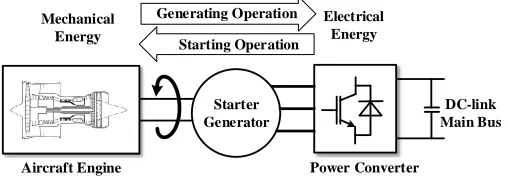
MEA is an electrical starter generator system which enables starting aircraft engines electrically and running as a generator when engines reach self-sustained speed [2]. A 45kVA, 32krpm aircraft electric starter generator system (ESG) has been presented in [5-6]. The ESG system consists of a Permanent Magnet Synchronous Machine [7-8] (PMSM) and a bi-directional power converter, as shown in Fig. 1. The machine is connected to the engine shaft and the converter operates as an interface between the ESG machine and a 270V DC bus. During the engine start-up process, the ESG accelerates the engine up to the ignition speed. In generation mode, the ESG extracts power from the engine shaft and supplies various onboard electrical loads through an AC/DC converter.
Power Converter
DC-link Main Bus
Aircraft Engine
Starter Generator Mechanical
Energy
Electrical Energy Starting Operation
[image:1.612.313.567.431.520.2]Generating Operation
Fig. 1. Diagram of the target starter generator system
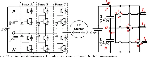
For the developed high-speed ESG, a three-level neutral point clamped (NPC) converter was chosen instead of a two-level topology due to its reduced switching loss and improved power quality[9-10]. Furthermore, each phase leg of the NPC converter can be seen as a single-pole three-throw switch as shown in Fig. 2[11]. This arrangement creates a total number of 27 voltage space vectors, allowing flexibility for the converter modulation.
However, one disadvantage of the topology is the potential voltage imbalance of two capacitors at the dc-link, i.e. neutral point (NP) voltage imbalance. The types of imbalance can be defined into two categories. One category is the continuous DC imbalance between the upper and lower capacitor voltages. This type of imbalance is typically induced by imperfections (i.e. capacitance mismatch, non-linear loads etc.) within the converter or/and the load [12]. On the DC side, such imbalance
A Modified Neutral-Point Balancing Space
Vector Modulation for Three-Level Neutral
Point Clamped Converters in High Speed
Drives
Chen Li, Student Member, IEEE, Tao Yang, Member, IEEE, Ponggorn Kulsangcharoen,
Member, IEEE Giovanni Lo Calzo, Member, IEEE, Serhiy Bozhko, Member, IEEE, Christopher
Gerada, Senior Member, IEEE and Patrick Wheeler, Senior Member, IEEE
would significantly increase the voltage stress placed on capacitors. On the DC side, the increased voltage stress can potentially cause capacitor or semiconductor device failures. On the AC side, a continuous DC imbalance will result in even order current harmonics. These induced harmonics can potentially aggravate the voltage imbalance, reduce the power quality and machine performance.
𝑬𝑫𝑪 𝟏 𝟐𝑬𝑫𝑪
𝟏 𝟐𝑬𝑫𝑪
𝑷
𝑶
𝑵
PM Starter Generator Phase-A Phase-B Phase-C
𝑬𝑫𝑪
𝟏 𝟐𝑬𝑫𝑪
𝟏 𝟐𝑬𝑫𝑪
𝑷
𝑶
𝑵
𝑰𝒂
𝑰𝒃
𝑰𝒄 P O
N
P P O
O N
N 𝑰𝒅𝒄
[image:2.612.51.296.134.228.2]𝑰𝑵𝑷
Fig. 2. Circuit diagram of a classic three-level NPC converter
The other category of NP voltage imbalance is the AC imbalance. This type of imbalance is essentially harmonic ripples (normally dominated by the third harmonic). This type of imbalance is an inherent property of the NPC converter using nearest-three-vector modulation (NTV)[13]. The amplitude of such ripple increases when the converter operates at low power factor and high modulation index conditions. To suppress this AC imbalance, larger capacitors are required. This is not ideal for aircraft applications as a larger capacitor means increased volume and weight of the overall system. The AC imbalance could cause distortion of converter output voltage and thus degrade performance of electrical machines.
Different solutions to eliminate these imbalances have been proposed recently. For the continuous DC imbalance, a classic family of solutions are based on common-mode voltage (CMV) injection[12]. Despite being simple, the performance of such method is weakened at lower power factor conditions. Its balancing capability also diminishes when the magnitude of fundamental current component is low. A six harmonic voltage injection is proposed in[14], where the dependency of power factor and fundamental current is addressed. However, the balancing capability at high power factors is reduced with this technique. Alternatively, the method proposed in [15] modifies the average NP current by injection of even-order harmonics [16] on the AC side. This method covers the gap in low power factor and low fundamental current operations. However, the drawback is an elevated AC side current THD.
To suppress the 3rd harmonic NP voltage ripple, carrier based pulse width modulation methods typically adopts variable
common mode voltage injection [17-18] whereas
nearest-three-vector (NTV) space vector modulation (SVM) methods tend to manipulate the redundant small vectors[11]. These methods work effectively at low to medium modulation index and high power factor operation conditions. However, their ripple suppression capabilities are limited when NPC operates at high modulation index and low power factor conditions. To address the dependency of modulation index and power factor, virtual space vector modulation method and its hybrids emerged[19-21]. This method creates a virtual vector by correlating duty cycles of adjacent small and medium vectors, thus achieving zero average NP current within each switching period. However, such method results in larger switching loss and increased common-mode noises. AC side
current THD is also increased at high modulation index. In addition, the zero neutral point current within each switching period is based on the assumption that the phase currents stays constant throughout each switching period, which would not be true under low pulse ratio condition.
For both types of imbalance, there are also hardware solutions such as adding extra balancing circuit[22], having two capacitors supplied by separate DC sources and back to back operation. With increased hardware component, the weight and volume will be increased as well as the cost.
Despite many NP balancing methods have been reported[13][15][23], none of them can deliver desirable performance under stringent operating conditions of ESG. A tailored NP balancing modulation method is therefore required. In this paper, operating characteristics of the target ESG system are elaborated and light load condition with high modulation index and low power factor is identified as the most vulnerable condition for NP imbalance and ripple. An alternative SVM method is proposed, aiming at maintaining NP voltage balanced and ripple minimized at near-unity modulation index and full power factor range whilst supporting bi-directional power flow. The performance of the method is validated by detailed simulation and experiments
II. PRINCIPLES OF OPERATION
A. ESG system characteristics and control
For the electric starter generator system, a 6-pole 36-slot surface mount PMSM is selected and classic vector control structure with synchronous reference frame current regulators based on conventional PI controllers and space vector modulation is implemented as shown in Fig.3. Vector control approach is selected over direct torque control(DTC) for the PMSM as DTC lack of direct current regulation, which is required in the control of power flowing between the engine shaft and aircraft DC-bus. Modulated model predictive control is also developed for the project as a parallel option [24], and has been achieved on a two-level converter based drive. However, model predictive control techniques have poor tolerance against parameter variations, whereas the ESG sometimes operates at a temperature as low as -70 ℃, which leads to significant parameter variation.
DC-link
S/G
Space vector Modulation abc
dq abc dq
𝑖𝑎𝑏𝑐
PI
PI
𝑑 𝑑𝑡 𝐿𝑠
𝜃𝑒
𝜔𝑒 𝑖𝑑 𝑖𝑞 +
− −
−
+ 𝜔𝑒𝜆𝑃𝑀
𝑉∗= 𝑉 𝑑∗2+ 𝑉𝑞∗2
I
𝑉𝑙𝑖𝑚 − 𝑖𝑞∗≤ 𝑖𝑠−𝑚𝑎𝑥2− 𝑖𝑑∗ 2
+ 𝑖𝑞∗
𝑖𝑑∗
𝑣𝑑∗ 𝑣𝑞∗
PI
𝜔𝑒∗ 𝜔𝑒
+
+
+ −
Starter Mode
PI
Generator Mode
Droop
−
𝐼𝑑𝑐 𝐼𝑑𝑐∗ 𝑖𝑞∗
𝑖𝑞∗
𝐿𝑠 𝐸𝑑𝑐
Flux Weakening Speed Control
[image:3.612.49.296.51.215.2]Current Control Droop Control
Fig. 3. Control structure for the target ESG system [28]
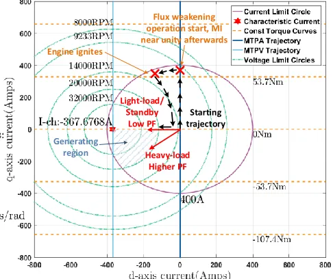
Based on the parameters of the machine given in table. II. in the appendix, the operational limits and trajectory of the ESG system is presented in Fig. 4. In the starter mode, the operation trajectory follows the maximum torque per amp (MTPA) line. When flux-weakening starts, the trajectory follows the current limit set by converter and voltage limit based on speed. After engine ignition at 10krpm, ESG is in standby mode and q-axis current falls to zero. Generation mode starts at 20krpm. At such speed, the fundamental electrical frequency is 1kHz. The control system sampling frequency and converter switching frequency are 16kHz, therefore a pulse ratio below 16:1 would be expected. This pulse ratio is significantly lower than typical drives. Furthermore, when the ESG is on standby or lightly loaded conditions, active power is fractional whilst reactive power is large due to flux weakening requirement. This makes the ESG working in a low power factor condition.
Generating region
Starting trajectory
Flux weakening operation start, MI near unity afterwards
Light-load/ Standby
Low PF
Heavy-load Higher PF
Engine ignites
Fig. 4. Operating trajectory of the target system
B. Conventional SVM strategy
PON[Ib]V3
OPN[Ia]V3
PNO[Ic]V3
ONP[Ia]V3 NOP[Ib]V3
NPO[Ic]V3
PPO[Ic]V5 OON[-Ic]V2
POO[-Ia]V4 ONN[Ia]V1
ONO[-Ib]V2
POP[Ib]V5 OPP[Ia]V5
NOO[-Ia]V2
OOP[-Ic]V4
NNO[Ic]V1
OPO[-Ib]V4 NON[Ib]V1
PPN[0]V4
PNN[0]V2
PNP[0]V4 NNP[0]V2
NPP[0]V4 NPN[0]V2
𝒂𝒃 𝒄𝒂
𝒃𝒄
PPP[0]V6
NNN[0]V0 OOO[0]V3
Sector I
𝑳 𝑴 𝑺 𝟎
𝐿1
𝑀 𝑆1
𝜽𝒓𝒆𝒇
𝒓𝒆𝒇
I II
III IV
𝟎 𝑆0 𝐿0
[image:3.612.315.563.55.179.2]a) b)
Fig. 5. Conventional SVM strategy a) space vector diagram for NPC converter b) space vector diagram in sector I
A total number of 27 switching states are available for a three-level NPC converter. As illustrated in Fig. 5, large vectors have magnitudes of 2VDC/3. When this vector applies, three phases are either connected to the positive or the negative rail. Thus, these vectors do not affect the NP voltage. For the null vectors, all three phases are connected to the same rail and thus do not affect the NP voltage either. For the medium vectors (with a magnitude of √33 𝑉𝐷𝐶), the three phases are connected to
the positive rail, the negative rail and the neutral point respectively. Take vector PNO for example. Phase C is connected to the neutral point. Therefore, the phase current 𝑖𝑐 is
flowing into the neutral point and thus affecting the neutral point potential. Small vectors are with magnitudes of 𝑉𝐷𝐶/3.
As they come in pairs with opposite polarity of NP current, they could be used to mitigate the NP voltage drift caused by the medium vectors[11].
Conventional SVM synthesize the reference voltage vector in the stationary reference frame based on the nearest three space vectors (NTV) [11]as in Fig. 6, where the triangle represents the Sector. I of the space vector hexagon in Fig. 5. Vector 𝑉0
represents the null vector; vector 𝑉𝑆0 & 𝑉𝑆1 represents the small vectors; vector 𝑉𝑀 represents the medium vector and vector 𝑉𝐿0
& 𝑉𝐿1 represents the large vector. The duty cycle of each vector is calculated based on voltage-time-area balance between the selected voltage space vectors and the reference vector, for example, a reference vector falls inside the region 3 in Fig 6 can be calculated from (1) and (2):
𝑉𝑟𝑒𝑓= 𝑑𝑆0𝑉𝑆0+ 𝑑𝐿0𝑉𝐿0+ 𝑑𝑀𝑉𝑀 (1)
𝑑𝑆0+ 𝑑𝐿0+ 𝑑𝑀= 1 (2)
III. ANALYSIS OF NEUTRAL POINT IMBALANCE
A. Source of NP ripple and imbalance
[image:3.612.52.295.436.640.2]𝑄 = ∫ 𝐼𝑁𝑃 𝑇𝑠
0
𝑑𝑡 (3)
Thus the variation of the neutral point voltage ∆𝑉𝑁𝑃 can then be
determined as:
∆𝑉𝑁𝑃=𝑄𝐶 =𝐼𝑇𝐴𝐶 (4)
where 𝐶 represents the capacitance of the DC-link capacitor. For the medium vector 𝑉𝑀 and the small vectors 𝑉𝑆0 and 𝑉𝑆1,
their neutral point current-time-area within each switching period are:
𝐼𝑇𝐴𝑀 = ∫ 𝐼𝑁𝑃−𝑀(𝑠𝑒𝑐𝑡𝑜𝑟) 𝑑𝑀𝑇𝑠
0
𝑑𝑡
𝐼𝑇𝐴𝑆0= ∫ 𝐼𝑁𝑃−𝑆0(𝑠𝑒𝑐𝑡𝑜𝑟)
𝑑𝑆0𝑇𝑠
0
𝑑𝑡
𝐼𝑇𝐴𝑆1= ∫ 𝐼𝑁𝑃−𝑆1(𝑠𝑒𝑐𝑡𝑜𝑟)
𝑑𝑆1𝑇𝑠
0
𝑑𝑡
(5)
where 𝑇𝑠 represents the switching period, 𝑑𝑥 represents the
[image:4.612.329.550.52.195.2] [image:4.612.104.240.177.254.2]duty cycle for corresponding vectors, and the neutral point current during corresponding voltage states can be found in Table. I.
Table. I. Neutral point current for medium and small vectors
Sector 𝐼𝑁𝑃−𝑀(𝑠𝑒𝑐𝑡𝑜𝑟) 𝐼𝑁𝑃−𝑆0(𝑠𝑒𝑐𝑡𝑜𝑟) 𝐼𝑁𝑃−𝑆1(𝑠𝑒𝑐𝑡𝑜𝑟)
I 𝑖𝑏 ±𝑖𝑎 ±𝑖𝑐
II 𝑖𝑎 ±𝑖𝑐 ±𝑖𝑏
III 𝑖𝑐 ±𝑖𝑏 ±𝑖𝑎
IV 𝑖𝑏 ±𝑖𝑎 ±𝑖𝑐
V 𝑖𝑎 ±𝑖𝑐 ±𝑖𝑏
VI 𝑖𝑐 ±𝑖𝑏 ±𝑖𝑎
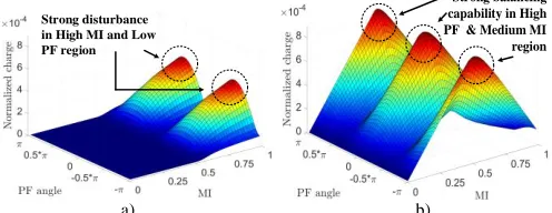
Assuming the phase currents are perfectly sinusoidal, the neutral point potential drift induced by the small vectors and the medium vector over a line cycle with regards to modulation index and power factor angle can be mapped using (5) and Table. 1, as shown in Fig. 6. It should be noted that the high power factor region refers to the area where the power factor angle is close to 0 or ±𝜋, and low power factor region refers to where the power factor angle is close to ±0.5𝜋.
Strong disturbance in High MI and Low PF region
Strong balancing capability in High PF & Medium MI region
a) b) Fig. 6. Neutral point potential drift caused by a) 𝑉𝑀 b) 𝑉𝑆0 and 𝑉𝑆1
It can be seen that the medium vector places a large impact on the neutral point potential in high modulation index and low power factor range. The small vectors can be used to decrease the impact of medium vectors on the neutral point voltage. This counterbalance capability is reflected by the current-time-area of small vectors for one whole duty cycle. The balancing ability of small vectors is shown in Fig. 6. As can be seen, this capability is stronger when the system operates at medium modulation index and higher power factor conditions.
Low PF and High MI region
NP Ripple Without Small Vector Compensation
[image:4.612.45.301.312.407.2]NP Ripple With Small Vector Compensation
Fig. 7. Neutral point ripple with and without small vector compensation
Conventional NTV-SVM technique for NPC converter swap the polarity of the small vectors in alternate switching periods instead of manipulating them against the medium vector within each switching period[13].Such method can effectively cancel the impact of small vectors but leave the disturbance from the medium vector untouched. This method serves as a benchmark for various neutral point balancing modulation approaches. The extent of the 3rd harmonic neutral point potential ripple with and without manipulation of small vectors is presented in Fig. 7. It can be observed that the manipulation of small vectors can reduce the extent of the neutral point ripple. However, at very high modulation index and lower power factor, the ripple remains almost unchanged. This indicates that the NTV-SVM method with small vector manipulation (NTV-SVM-SM) has very poor balancing capability in this operating condition.
B. Issue with high fundamental frequency
Exploiting the redundancy of the small vectors to balance to the neutral point voltage requires feedback information of phase currents. Both quantities can be seen as constant at the presence of the 1.5 sample period delay in digital control systems, as long as the pulse ratio is high enough. However, as explained in section II, the pulse ratio of the target ESG system can be lower than 16:1 in the generating mode. Under this operation condition, there can be significant differences between the sampled phase currents and the phase currents when control actions are applied. Assuming the target ESG system is operating at 1kHz fundamental frequency, the movement of rotor electrical position 𝜃𝑎𝑑𝑣 during 1.5 sample
period can be obtained by:
𝜃𝑎𝑑𝑣 = 1.5𝜔𝑜𝑇𝑠 (6)
Where 𝑇𝑠 represents one sample period; 𝜔𝑜 represents the
fundamental frequency. The calculated advance angle 𝜃𝑎𝑑𝑣 is 3
16𝜋. Since the ESG uses a PMSM, the rotor flux and stator flux
[image:4.612.49.297.516.612.2]Sector I Sector IISector IIISector IVSector VSector VI
𝒊𝒄 𝒊𝒃 𝒊𝒂 𝒊𝒄 𝒊𝒃
Zero
- Actual
𝒊𝒂
Zero
𝒊𝒂 𝒊𝒄 𝒊𝒃 𝒊𝒂 𝒊𝒄 𝒊𝒃
Sector I Sector II Sector IIISector IVSector VSector VI - Actual
a) b)
Fig. 8. Variation of NP current of 𝑉𝑆0 a) before & b) after 1.5 𝑇𝑠 of sample
delay. Blue line: the sampled current iNP; red line: the actual current when the
control action applied
For the small vector 𝑉𝑆0, its corresponding neutral point
current over a line cycle under the influence of the 1.5 sample delay with respect to different power factor angle is presented in Fig. 8. The term ‘NP current - actual’ refers to the neutral point current when the control actions are applied. When the power factor angle is 0.4𝜋, both the sampled NP current and the actual NP current have the same polarity over a full line cycle. However, when the power factor angle is 0.9𝜋, the sampled NP current and the advanced NP current (i.e. NP currents when control output applied) have the opposite polarity in the shaded region, during which erroneous would be selected if such effect is not compensated.
PF angle=0.4𝝅,
𝒊𝑵𝑷 for 𝑺0 has no zero-crossing
[image:5.612.47.297.52.159.2]PF angle=0.9𝝅, 𝒊𝑵𝑷 for 𝑺0 has large zero-crossing
Fig. 9. NP current error ratio for small vectors
The error ratio, hence the possibility of erroneous neutral point current polarity being selected for small vectors over a full power factor range is presented in Fig. 9. Combining small vector 𝑉𝑆0 and 𝑉𝑆1, the possibility of erroneous small vector being selected exceeds 50% over a significant power factor range, at which the NP balancing ability offered by small vector redundancy would completely diminish.
IV. THE PROPOSED MODULATION TECHNIQUE
A. Principle of operation
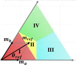
The proposed space vector modulation scheme suppresses neutral point imbalance and ripple by restricting the use of the medium vector at higher modulation index. The sectors are divided for sub-sectors as given in Fig. 10.
IV
II III I
𝒎𝒓𝒆𝒇
𝒎𝒈
𝒎𝒉
𝜽𝒓𝒆𝒇
Fig. 10. Region division for the proposed SVM
The reference voltage region identification approach is presented in table. II. Where the indices 𝑉𝑟𝑒𝑓 and 𝑉𝑟𝑒𝑓 for a given reference voltage with a magnitude of 𝑉𝑟𝑒𝑓 and a phase
angle of 𝜃𝑟𝑒𝑓 can be obtained by:
[𝑚𝑚𝑔
ℎ] =
√3
2𝑉𝐷𝐶[1 −10 2 ] [
𝑉𝑟𝑒𝑓cos(𝜃𝑟𝑒𝑓)
[image:5.612.378.502.53.159.2]𝑉𝑟𝑒𝑓sin(𝜃𝑟𝑒𝑓)] (7)
Table. II. Reference voltage region identification strategy
Region Condition for 𝑚𝑔 and 𝑚ℎ
I 𝑚𝑔+𝑚ℎ≤0.5
II 𝑚𝑔+𝑚ℎ>0.5 && 𝑚𝑔< 0.5 && 𝑚ℎ< 0.5
III 𝑚𝑔> 0.5 && 𝑚ℎ> 0.5 && 𝑚𝑔≥ 𝑚ℎ
IV 𝑚𝑔> 0.5 && 𝑚ℎ> 0.5 && 𝑚𝑔< 𝑚ℎ
In region I given in Fig. 11, the reference vector is synthesized by a null vector and two small vectors. The duty cycles for each vector are given as:
𝑑𝑆0= 2 ∙ 𝑀 ∙ sin(
𝜋 3− 𝜃𝑟𝑒𝑓) 𝑑𝑆1= 2 ∙ 𝑀 ∙ sin(𝜃𝑟𝑒𝑓)
𝑑0= 1 − 𝑑𝑆0− 𝑑𝑆1
(8)
In the region II, the reference voltage vector is synthesized by the medium vector and the two small vectors.
The duty cycles for each vector are given in (9). 𝑑𝑆0= 1 − 2 ∙ 𝑀 ∙ sin(𝜃𝑟𝑒𝑓)
𝑑𝑆1= 1 + 2 ∙ 𝑀 ∙ sin(𝜃𝑟𝑒𝑓−
𝜋 3) 𝑑𝑀 = 2 ∙ 𝑀 ∙ sin (𝜃𝑟𝑒𝑓+
𝜋 3) − 1
(9)
It should be emphasized that the target ESG system operates mostly in generating mode, where a high modulation index is constantly required due to the need of flux weakening. Therefore, the voltage space vector would mostly fall inside region III and IV. The region I and II would only be used for a short period in the starting mode when the ESG is running at low speed.
I II
III IV
Region I – Low MI Region II – Medium MI
𝑆1 𝑆1 𝑀
III IV
II I
𝜽𝒓𝒆𝒇
𝜽𝒓𝒆𝒇
𝟎 𝑆0 𝑆0
𝒓𝒆𝒇 𝒓𝒆𝒇
[image:5.612.49.278.344.488.2] [image:5.612.315.564.623.733.2]Fig. 11. Proposed SVM a) region 1 b) region 2
III
II I
IV
Region III – High MI Region IV – High MI
𝜽𝒓𝒆𝒇 𝒓𝒆𝒇 𝑆1 𝐿1 𝐿1 III IV II I 𝒓𝒆𝒇 𝐿0 𝐿0 𝑆0 𝜽𝒓𝒆𝒇
[image:6.612.312.566.52.231.2]a) b) Fig. 12. Proposed SVM a) region 3 b) region 4
In the third and the forth region, the modulation index is high. The reference voltage vector is synthesized by two large vectors and the adjacent small vector as shown in Fig. 12. The duty cycles for each vector are given in (10) and (11).
𝑑𝑆0= 2 − 2 ∙ 𝑀 ∙ sin(𝜃𝑟𝑒𝑓+
𝜋 3) 𝑑𝐿0= √3 ∙ M ∙ cos(𝜃𝑟𝑒𝑓) − 1
𝑑𝐿1= 𝑀 ∙ sin(𝜃𝑟𝑒𝑓)
(10)
𝑑𝐿0= 𝑀 ∙ sin(𝜃𝑟𝑒𝑓−
𝜋 3) 𝑑𝐿1= √3 sin(𝜃𝑟𝑒𝑓+
𝜋 6) − 1 𝑑𝑆1= 2 − 2 ∙ 𝑀 ∙ sin(𝜃𝑟𝑒𝑓+
𝜋 3)
(11)
B. Small vector selection
Accurately manipulate the polarity of small vectors under high modulation index and high fundamental frequency is the key to neutral point balancing.
Based on the potential difference between the upper and the lower capacitors ∆𝑉𝐷𝐶, the q-axis current Iq, the small vectors for different sectors can be determined and are presented in Fig. 13. The potential difference ∆𝑉𝐷𝐶 is defined as.
∆𝑉𝐷𝐶= 𝑉𝐶𝑢− 𝑉𝐶𝑙 (12)
Where 𝑉𝐶𝑢 and 𝑉𝐶𝑙represent upper and lower capacitor
voltages respectively. Among the required information, sector information and the polarity of Iq are already known in SVM duty cycle calculation and don’t have to be calculated again. The only feedback required are the measurements of the capacitor voltages. Therefore, the approach can be conveniently implemented as a simple look-up table. For instance, assuming that the ESG system is generating (i.e. Iq< 0A), if the reference voltage vector falls inside sector II and the ∆𝑉𝐷𝐶 term is positive (denoted as Cond. 1 in Fig. 13), the small
vector 𝑉𝑆0 should be selected such that the current iNP is the inversed corresponding phase current (i.e. –ic). Alternatively, if ESG is cranking the engine (i.e. Iq>0A) and reference voltage vector falls in sector I, when the ∆𝑉𝐷𝐶 term is positive (denoted as Cond. 2 in Fig. 13), small vector 𝑉𝑆1 should be selected such
that the current iNP is the same as its corresponding phase current (i.e. ic).
NPP[0]
PON[Ib]
OPN[Ia]
PNO[Ic]
ONP[Ia]
NOP[Ib]
NPO[Ic] PPO[Ic]
OON[-Ic]
POO[-Ia] ONN[Ia]
ONO[-Ib] POP[Ib] OPP[Ia]
NOO[-Ia]
OOP[-Ic] NNO[Ic] OPO[-Ib] NON[Ib]
PPN[0] PNN[0] PNP[0] NNP[0] NPP[0] NPN[0] 𝒂𝒃 𝒄𝒂 𝒃𝒄 PPP[0] NNN[0] OOO[0]
PON[Ib]
OPN[Ia]
PNO[Ic]
ONP[Ia]
NOP[Ib]
NPO[Ic] PPO[Ic]
OON[-Ic]
POO[-Ia] ONN[Ia]
ONO[-Ib] POP[Ib] OPP[Ia]
NOO[-Ia]
OOP[-Ic] NNO[Ic] OPO[-Ib] NON[Ib]
PPN[0] PNN[0] PNP[0] NNP[0] NPN[0] 𝒂𝒃 𝒄𝒂 𝒃𝒄 PPP[0] NNN[0] OOO[0] 𝑰𝒒
Sector II, IV and VI Small Vector VS0 polarity Small Vector VS1 polarity
I
III
V
II
IV
VI
𝑰𝒒 𝑰𝒒 𝑰𝒒∆ 𝑫𝑪
∆ 𝑫𝑪
∆ 𝑫𝑪
∆ 𝑫𝑪
Original Original Reversed
Reversed 𝑰𝒒 close to zero
𝑰𝒒 close to zero 𝑰𝒒 close to zero
𝑰𝒒 close to zero
Sector I, III and V
Cond. 1.
Cond. 2.Original
Original Original Original Original Original Reversed Reversed Reversed Reversed Reversed Reversed
Fig. 13. Small vector polarity selection – Iq method
Nevertheless, the above-mentioned method is prone to error when the ESG system is on standby mode or lightly loaded. Under these conditions, the q-axis current is very close to zero, in which case the control algorithm might generate erroneous demands under the effects of q-axis current zero-crossing. Therefore, an alternative method is required and shown in Fig. 14. a)This approach determines the polarity of the small vector based on the neutral point current iNP and the imbalance of DC-link capacitor voltage ∆𝑉𝐷𝐶. The neutral point current INP is obtained by selecting from the corresponding phase current based on the information given in table. I. Therefore no additional sensors is required to obtain neutral point current INP. For both small vectors 𝑉𝑆0 and𝑉𝑆1, assuming its corresponding
converter phase leg which connects to the neutral point has positive current flowing (phase current flows from converter to machine winding), and the ∆𝑉𝐷𝐶 term is positive, the polarity of
the small vectors should be selected such that its NP current is the inverted ones and discharge the neutral point.
∆ 𝑫𝑪
𝑰𝑵𝑷
Small Vector VS0 & VS1 polarity Original
Reversed
Reversed
Original
𝑁𝑜
𝒊𝒒 > 𝑰𝒉𝒊𝒈𝒉? 𝒊𝒒 < 𝑰𝒍𝒐𝒘?
Determine sector and region for 𝜶𝜷𝒓𝒆𝒇
𝜶𝜷 𝒓𝒆𝒇
generated by Current Loop
Calculate 𝒅𝑳𝟎, 𝒅𝑳𝟏 and 𝒅𝒔
Pulse sequencing
𝐀𝐩𝐩𝐥𝐲 𝐩𝐮𝐥𝐬𝐞𝐬
Previous method?
Phase current delay compensation, determine 𝒊𝑵𝑷
Obtain 𝑺𝟎/𝑺𝟏 polarity by
∆ 𝑵𝑷 and 𝒊𝑵𝑷 Obtain 𝑺𝟎/𝑺𝟏
polarity by
∆ 𝑵𝑷 and 𝒊𝒒
𝑌𝑒𝑠 𝑌𝑒𝑠
𝑁𝑜
𝑖𝑁𝑃 method
𝑖𝑞 method Transition Mechanism
[image:6.612.47.298.54.182.2]a) b)
Fig. 14. Small vector polarity selection for the proposed SVM a) INP method
b) Operating procedure for proposed SVM
[image:6.612.316.562.453.561.2]small vector. If the absolute value is larger than 𝑖ℎ𝑖𝑔ℎ, the Iq method is used. The transition band is in between, and the boundary values 𝑖𝑙𝑜𝑤 and 𝑖ℎ𝑖𝑔ℎ are defined based on
experimental measurements.
C. Delay compensation & Pulse sequence
To compensate the high fundamental frequency induced delay issue discussed in section III.B, a simple solution is proposed in this section. The measured phase current vector 𝑖𝑠
can be advanced by 1.5𝑇𝑠 with the fundamental frequency as in (13):
𝑖𝑠𝑎𝑑𝑣= 𝑖𝑠∙ 𝑒−𝑗∙1.5𝜔𝑜𝑇𝑠 (13)
The advanced phase current will then be used in the small vector polarity determination method described in Fig. 14. In practical implementation, the small vector polarity determination method described in Fig. 13 would not be affected as it does not need phase current information.
Pulse sequencing affects the switching loss, thus affecting the efficiency of the system. It is worth noting that with the restriction of medium usage described in section IV.A, more switching events are involved as sometimes the state of a phase leg has to commutate between ‘P’ and ‘N’ state, hence taking two steps in one transition. To minimize such effect, the numbering system described in [11] is implemented (i.e. states P = 2, O=1 and N=0 and the vector number is the sum of states of three legs.). The selected vectors are applied in an ascending or descending sequence, so that the switching events within each region and the switching events between adjacent regions are minimized.
D. Difference with respect to previous methods
Nearest Three Virtual Vector Method (N3VV) I
𝑆1 𝐿1
𝑀
𝑉 II
III IV V
[image:7.612.46.259.414.567.2]0 𝑆0 𝐿0
Fig. 15. NTVV-SVM
As mentioned in the introduction, a seemly similar modulation technique namely the nearest three virtual space vector modulation (NTVV-SVM) was introduced to suppress the third harmonic voltage ripple at the DC-link neutral point. The essence of the NTVV-SVM is to suppress the usage of the medium vector 𝑉𝑀 by replacing it with a virtual voltage space vector 𝑉𝑉 which is shown in Fig. 15. Its formulation is given in
the following equation, where 𝑑𝑉 is the calculated virtual vector duty cycle.
𝑉𝑉=
1
3𝑑𝑉𝑉𝑆0+ 1
3𝑑𝑉𝑉𝑆1+ 1 3𝑑𝑉𝑉𝑀
(14)
Based on Table. I and Fig. 5. a), the implementation of the virtual vector 𝑉𝑉 can be manipulated in such a way that all three
phase currents are connected to the DC-link neutral point for the same amount of time. Assuming the three phase currents stay constant in one switching period and ignoring all common-mode noises, then the following condition would apply:
𝑖𝑁𝑃−𝑉=
1 3𝑖𝑎+
1 3𝑖𝑏+
1 3𝑖𝑐= 0
(15)
Hence the virtual vector neutral point current 𝑖𝑁𝑃−𝑉 is zero, and it is independent of the power factor.
The original NTVV-SVM technique aims at suppressing low frequency neutral point voltage ripple so that the size of DC-link capacitors wouldn’t have to be significantly increased to allow low power factor operation. Many improved NTVV-SVM techniques and hybrid solutions have been introduced subsequently. However, for a neutral point clamped converter installed in an aircraft electric starter generator, the NTVV-SVM methods may not be entirely suitable. Illustrated in chapter. II, the ESG features high modulation index, low pulse ratio and full power factor range.
Presented in chapter. III. B, under a low pulse ratio, the assumption of three phase currents stay constant during a switching period hence (15) is no longer valid. Therefore, the use of the virtual vector neutral point current can not make the neutral point current zero and the neutral point will not be balanced.
At high modulation indices, both the NTVV-SVM and the proposed method would allocate the majority of duty cycle to large vectors. Furthermore, the use of NTVV-SVM method may result in higher number of switching at medium to high modulation index operation. The NTVV-SVM presented in [29] contains an optimized pulse pattern which reduces its number of commutations to the minimum.
𝐿1
6
𝐿0 𝑆1
𝑉
𝑆0
𝑆1 𝐿1
𝐿0 𝑆0
6
10
6/8 6/8
a) b)
Fig. 16. Number of commutations per switching period for a) NTVV-SVM method b) the proposed method in medium to high modulation region
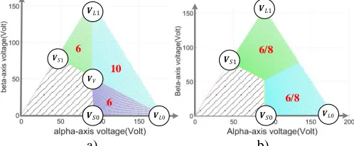
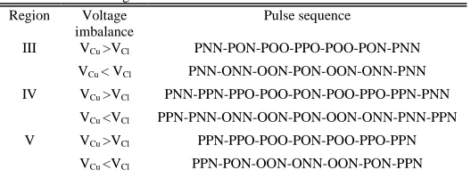
As the converter in the ESG operates at high modulation index for more 99% of time, the number of commutations in medium to high modulation index region for both NTVV-SVM method and the proposed method are analysed and presented in Fig.18, detailed pulse pattern is given in table. IV and table. V respectively in the appendix. Seen from Fig. 16, the optimized NTVV-SVM pulse pattern requires 6 switching actions per switching period for region III and V and 10 switching actions for region IV. The proposed method requires 6 or 8 switching actions depending on which particularly small vector is selected. Assuming the instantaneous voltage of the upper capacitor 𝑉𝐶𝑢 is 50% of the time larger than that of lower
[image:7.612.314.563.425.528.2]medium to high modulation index region, whereas the proposed method requires 7. Therefore, for more than 99% of ESG operation time, the NTVV-SVM requires 14.3% more commutations than the proposed method.
V. SIMULATIONS
A simulation model for the target ESG system is built within the PLECS/Simulink environment, the parameters are given in Section II. Both the conventional SVM method and the posed SVM method are evaluated. In simulation, the target ESG system initially operates in starting mode, and flux weakening operation starts at approximately 0.45s. Followed by engine ignition, the engine accelerates to 20krpm and the ESG system is switched to generating mode. The droop control takes over the DC-link voltage regulation, generating q-axis current references to the inner current controller. A 15kw resistive load is connected to the DC-link at 1.1s, resulting in a drop of the overall DC-link voltage and a step increase of negative q-axis current.
It should be emphasized that a typical engine start process takes more than 60s. In our simulation, the starting process is significantly scaled down to save simulation time and computational resource.
Denoted in Fig. 17, a large negative d-axis current is constantly required for flux weakening in generating mode. This indicates the system constantly operates at low power factor conditions with near unity modulation index. This working condition also pushes the converter into the ripple-prone region (denoted in red in Fig. 8).
Starting operation, positive iq hence torque is large
Engine ignites, starting operation ends, iq drops to 0 Generating operation, negative iq
Deep flux-weakening is constantly required
a)
Generating operation, negative iq
Starting operation, positive iq hence torque is large
Engine ignites, starting operation ends, iq drops to 0
[image:8.612.68.278.408.594.2]b)
Fig. 17. Simulated ESG system dq-currents a) in a typical S/G process b) ESG system dq-currents trajectory(right)
Engine ignites ESG on standby mode Generating
Fig. 18. DC-link capacitor voltages in S/G process – NTV-SVM-SM method
Engine ignites ESG on standby
mode
Generating
Fig. 19. DC-link capacitor voltages in S/G process – proposed method
Engine ignites, starting
operation ends ESG on
[image:8.612.320.557.546.690.2]standby mode
Fig. 20. ESG machine speed in S/G process
A 1.5 sample period delay is applied to switching signals. From the capacitor voltages presented in Fig. 18 and Fig. 19, it can be concluded that the proposed method can maintain the DC-link neutral point voltage balanced and its ripple minimized in comparison to the NTV-SVM-SM method with small vector compensation. ESG machine speed is given in Fig. 20.
0.372 0.374 0.374
0.348 0.346 0.348
0.335 0.541
0.624 0.086
0.141 0.166
0 0.3 0.6 0.9 1.2 1.5 1.8
NTV-SVM Method
Proposed Method
NTVV-SVM Method
Diode reverse
IGBT switching
Diode cond
IGBT cond
L
os
s/
k
w
0.2 0.2 0.2
0.69 0.69 0.69
0.269 0.427 0.503
0.068
0.116 0.137
0 0.3 0.6 0.9 1.2 1.5 1.8
NTV-SVM Method
Proposed Method
NTVV-SVM Method
Diode reverse
IGBT switching
Diode cond
IGBT cond
L
os
s/
k
w
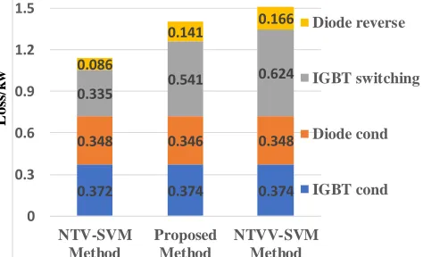
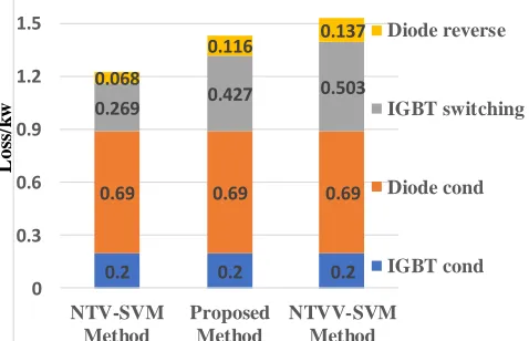
Fig. 22. Converter loss comparison when ESG is generating 30kw of active power at 20krpm
Further to the neutral point voltage balancing and ripple reduction. An accurate converter loss model is constructed within PLECS environment based on the switching characteristics of the power modules. The loss breakdown for the conventional NTV method, the proposed method and the NTVV method with optimized pulse pattern are presented in Fig. 21 and Fig. 22. When the ESG system is operating in generating mode at 20krpm of shaft speed, the converter losses for standby mode and 30kw of active power generation are presented respectively. The proposed method indeed causes a slight increase of the converter loss, but it is still lower than the seemly similar NTVV modulation method even if the pulse pattern for NTVV method is optimized. From standby mode to generating mode, the combined converter loss tend not to vary significantly as a large reactive power is constantly flowing between the machine and the converter due to flux weakening.
VI. EXPERIMENTAL RESULTS
The proposed SVM method is verified with a 45kVA, 32krpm prototype of ESG system. The hardware structure is presented in Fig. 23. A 150kw prime mover and the homebrewed ESG machine are placed in an isolated room for safety consideration. The three-level NPC converter along with DSK6713/Actel a3p400 control platform, DC source, prime mover controller, host PC are placed outside of the high-speed room. The selected devices for the NPC converter are IGBT modules from Infineon. The prime mover emulates aircraft engine shaft, coupled with ESG machine. The NPC converter interfaces the ESG machine and the 270V DC-link. AC-side parameters are monitored by PPA5530 power analyzer.
3L-DNPC Converter DC-link SPMSM
[image:9.612.314.563.53.221.2]Oil Cooling Sys Prime Mover Control Power Analysor Outside High Speed Room Prime Mover
Fig. 23. ESG test rig setup
Experimental results presented in this section focus on the generation mode of the ESG system, and particularly the light load condition. This is because the neutral point balancing problem mainly occurs in such operating condition. The results when ESG system operates in starting mode are not presented as it accounts for less than 1% of the operation time and is out of the scope of this paper.
The NP balancing results for the proposed SVM method and the NTV-SVM-SM method are obtained when the ESG system is operated in generating mode at 20krpm in light load conditions. The q-axis current reference is -10A; the modulation index is above 0.9; the power factor is below 0.1. Line voltage and phase currents are presented in Fig. 24, where the distortions of phase currents originate from low machine inductance. DC-link capacitor voltages for NTV-SVM-SM method and the proposed SVM method during light load condition are given in Fig. 25. Due to limited balancing capability in such operating condition and small vector manipulation inaccuracies caused by low pulse ratio, a large continuous DC imbalance can be seen when NTV-SVM-SM method is used. Harmonic contents of NP voltage for both methods in the same condition are presented in Fig. 26, a large 3rd harmonic is observed, indicating a bigger pair of DC-link capacitors are required to absorb the ripple. Results shown the proposed SVM method maintains NP voltage balanced and ripple minimized under very low power factor (PF), near-unity modulation index (MI) and low pulse ratio.
𝒊𝒂𝒃𝒄
𝒂𝒃 100V/div
[image:9.612.52.291.55.209.2]100A/div
[image:9.612.314.566.551.690.2]100A/div 𝑪𝒍
𝑪𝒖
𝒂𝒃
∆ 𝑵𝑷
𝒊𝒑𝒉−𝒂
NTV-SVM-SM method
Proposed method 200V/div
[image:10.612.319.554.51.143.2]100V/div 100V/div
Fig. 25. Transition from NTV-SVM-SM to proposed SVM at light load (iq = -15A, Averaged MI = 0.912, Averaged PF = 0.137)
3rd harmonic
DC imbalance
a) b)
Fig. 26. Processed experimental results a) FFT of NP voltage difference for both methods b) AC-side current THD for NTV-SVM and proposed SVM
AC-side current THD is monitored by power analyzer from standby to heavy-load condition at 20krpm. The results are given in Fig. 26, proving the proposed method delivers better performance in light-load conditions.
VII. CONCLUSION
This paper presents a comprehensive study on the DC-link capacitor neutral point balancing for 3-level NPC converter in aircraft ESG systems, the conclusions are applicable to all 3-level NPC converter used in high speed drives. The operating characteristics of the ESG including bi-directional power flow, very low power factor, low pulse ratio and near unity modulation index is analyzed. Basic SVM principles for 3-level NPC converter is reviewed, and the source of neutral point ripple and imbalance under ESG operating conditions are elaborated. Further to the analysis, an alternative SVM technique is proposed, which is capable of suppressing neutral point voltage ripple and eliminate imbalance at light load condition. Two small vector polarity selection strategies are proposed so that the issues emerged due to low pulse ratio and load variation are addressed. Simulation and experimental results obtained from a ESG prototype demonstrate the proposed SVM technique delivers superior performance in terms of neutral point voltage ripple, balancing and output current THD under light load condition
APPENDIX Table. III. Starter generator system parameters
Ld 99uH
Lq 99uH
Is-max 400A
Vdc 270V
PM flux 0.0364 Vs/rad
Pole pair 3
Base speed 8000rpm Converter switching frequency 16kHz Control system sampling frequency 16kHz Fundamental frequency in generating 1~1.75kHz
Table. IV. Optimized NTVV-SVM pulse pattern in sector I in medium to high modulation index region
Region Voltage imbalance
Pulse sequence
III VCu >VCl PNN-PON-POO-PPO-POO-PON-PNN
VCu < VCl PNN-ONN-OON-PON-OON-ONN-PNN
IV VCu >VCl PNN-PPN-PPO-POO-PON-POO-PPO-PPN-PNN
VCu <VCl PPN-PNN-ONN-OON-PON-OON-ONN-PNN-PPN
V VCu >VCl PPN-PPO-POO-PON-POO-PPO-PPN
[image:10.612.50.296.52.319.2]VCu <VCl PPN-PON-OON-ONN-OON-PON-PPN
Table. V. Pulse pattern in sector I in medium to high modulation index region for the proposed method
Region Small vector
Pulse sequence
III POO PPN-PNN-POO-PNN-PPN ONN PPN-PNN-ONN-PNN-PPN IV PPO PNN-PPN-PPO-PPN-PNN OON PNN-PPN-OON-PPN-PNN
ACKNOWLEDGMENT
This project has received funding from the Clean Sky 2 Joint Undertaking under the European Union’s Horizon 2020 research and innovation program under grant agreement No 807081.
REFERENCES AND FOOTNOTES
[1] P. Wheeler and S. Bozhko, “The More Electric Aircraft: Technology and challenges.,” IEEE Electrif. Mag., vol. 2, no. 4, pp. 6–12, Dec. 2014. [2] S. Roggia, F. Cupertino, C. Gerada, and M. Galea, “A Two degrees of
freedom system for wheel traction applications,” IEEE Trans. Ind. Electron., vol. 46, no. c, 2017.
[3] Y. Huangfu, S. Pang, B. Nahid-Mobarakeh, L. Guo, A. K. Rathore, and F. Gao, “Stability Analysis and Active Stabilization of On-board DC Power Converter System with Input Filter,” IEEE Trans. Ind. Electron., vol. 65, no. 1, pp. 1–1, 2017.
[4] J. Borg Bartolo, M. Degano, J. Espina, and C. Gerada, “Design and Initial Testing of a High-Speed 45-kW Switched Reluctance Drive for Aerospace Application,” IEEE Trans. Ind. Electron., vol. 64, no. 2, pp. 988– 997, Feb. 2017.
[5] S. Yin, K. J. Tseng, R. Simanjorang, Y. Liu, and J. Pou, “A 50-kW High-Frequency and High-Efficiency SiC Voltage Source Inverter for More Electric Aircraft,” IEEE Trans. Ind. Electron., vol. 64, no. 11, pp. 1–1, 2017. [6] S. Bozhko, S. S. Yeoh, F. Gao, and C. Hill, “Aircraft starter-generator system based on permanent-magnet machine fed by active front-end rectifier,” in IECON 2014 - 40th Annual Conference of the IEEE Industrial Electronics Society, 2014, pp. 2958–2964.
[7] N. Fernando, G. Vakil, P. Arumugam, E. Amankwah, C. Gerada, and S. Bozhko, “Impact of Soft Magnetic Material on Design of High Speed Permanent Magnet Machines,” IEEE Trans. Ind. Electron., vol. 46, no. c, pp. 1–1, 2016.
[image:10.612.309.573.172.272.2] [image:10.612.307.573.302.376.2][9] T. B. Soeiro and J. W. Kolar, “The new high-efficiency hybrid neutral-point-clamped converter,” IEEE Trans. Ind. Electron., vol. 60, no. 5, pp. 1919–1935, 2013.
[10] M. Schweizer, T. Friedli, and J. Kolar, “Comparative Evaluation of Advanced 3-phase 3-level Inverter/Converter Topologies against 2-level Systems,” IEEE Trans. Ind. Electron., vol. 60, no. 12, pp. 5515–5527, 2013. [11] Y. Jiao, F. C. Lee, and S. Lu, “Space vector modulation for three-level NPC converter with neutral point voltage balance and switching loss reduction,” IEEE Trans. Power Electron., vol. 29, no. 10, pp. 5579–5591, 2014.
[12] C. Newton and M. Sumner, “Neutral point control for multi-level inverters: theory, design and operational limitations,” in IAS ’97. Conference Record of the 1997 IEEE Industry Applications Conference Thirty-Second IAS Annual Meeting, vol. 2, pp. 1336–1343.
[13] N. Celanovic and D. Boroyevich, “A comprehensive study of neutral-point voltage balancing problem in three-level neutral-point-clamped voltage source PWM inverters,” IEEE Trans. Power Electron., vol. 15, no. 2, pp. 242–249, Mar. 2000.
[14] H. Akagi and T. Hatada, “Voltage Balancing Control for a Three-Level Diode-Clamped Converter in a Medium-Voltage Transformerless Hybrid Active Filter,” IEEE Trans. Power Electron., vol. 24, no. 3, pp. 571–579, Mar. 2009.
[15] J. Pou, D. Boroyevich, and R. Pindado, “Effects of Imbalances and Nonlinear Loads on the Voltage Balance of a Neutral-Point-Clamped Inverter,” IEEE Trans. Power Electron., vol. 20, no. 1, pp. 123–131, Jan. 2005.
[16] Jie Shen, S. Schröder, R. Rösner, and S. El-Barbari, “A Comprehensive Study of Neutral-Point Self-Balancing Effect in Neutral-Point-Clamped Three-Level Inverters,” IEEE Trans. Power Electron., vol. 26, no. 11, pp. 3084–3095, Nov. 2011.
[17] C. Wang and Y. Li, “Analysis and calculation of zero-sequence voltage considering neutral-point potential balancing in three-level NPC converters,” IEEE Trans. Ind. Electron., vol. 57, no. 7, pp. 2262–2271, 2010. [18] Y. Zhang, J. Li, X. Li, Y. Cao, M. Sumner, and C. Xia, “A Method for the Suppression of Fluctuations in the Neutral-Point Potential of a Three-Level NPC Inverter With a Capacitor-Voltage Loop,” IEEE Trans. Power Electron., vol. 32, no. 1, pp. 825–836, Jan. 2017.
[19] S. Busquets-Monge, J. Bordonau, D. Boroyevich, and S. Somavilla, “The nearest three virtual space vector PWM - a modulation for the comprehensive neutral-point balancing in the three-level NPC inverter,” IEEE Power Electron. Lett., vol. 2, no. 1, pp. 11–15, Mar. 2004.
[20] C. Xia, H. Shao, Y. Zhang, and X. He, “Adjustable proportional hybrid SVPWM strategy for neutral-point-clamped three-level inverters,” IEEE Trans. Ind. Electron., vol. 60, no. 10, pp. 4234–4242, 2013.
[21] G. I. Orfanoudakis, M. A. Yuratich, and S. M. Sharkh, “Nearest-vector modulation strategies with minimum amplitude of low-frequency neutral-point voltage oscillations for the neutral-point-clamped converter,” IEEE Trans. Power Electron., vol. 28, no. 10, pp. 4485–4499, 2013. [22] W. Zhao, X. Ruan, D. Yang, X. Chen, and L. Jia, “Neutral Point Voltage
Ripple Suppression for a Three-Phase Four-Wire Inverter With an Independently Controlled Neutral Module,” IEEE Trans. Ind. Electron., vol. 64, no. 4, pp. 2608–2619, 2017.
[23] J. Shen, S. Schroder, B. Duro, and R. Roesner, “A Neutral-Point Balancing Controller for a Three-Level Inverter With Full Power-Factor Range and Low Distortion,” IEEE Trans. Ind. Appl., vol. 49, no. 1, pp. 138– 148, Jan. 2013.
[24] S. S. Yeoh, T. Yang, L. Tarisciotti, C. I. Hill, S. Bozhko, and P. Zanchetta, “Permanent Magnet Machine based Starter-Generator System with Modulated Model Predictive Control,” IEEE Trans. Transp. Electrif., pp. 1–1, 2017.
[25] Jang-Mok Kim and Seung-Ki Sul, “Speed control of interior permanent magnet synchronous motor drive for the flux weakening operation,” IEEE Trans. Ind. Appl., vol. 33, no. 1, pp. 43–48, 1997.
[26] F. Gao et al., “Comparative Stability Analysis of Droop Control Approaches in Voltage-Source-Converter-Based DC Microgrids,” IEEE Trans. Power Electron., vol. 32, no. 3, pp. 2395–2415, Mar. 2017. [27] F. Gao, S. Bozhko, A. Costabeber, G. M. Asher, and P. W. Wheeler,
“Control Design and Voltage Stability Analysis of a Droop-Controlled Electrical Power System for More Electric Aircraft,” IEEE Trans. Ind. Electron., pp. 1–1, 2017.
[28] S. Bozhko, M. Rashed, C. I. Hill, S. S. Yeoh, and T. Yang, “Flux Weakening Control of Electric Starter-Generator Based on Permanent-Magnet Machine,” IEEE Trans. Transp. Electrif., pp. 1–1, 2017.
[29] A. Choudhury, P. Pillay, and S. S. Williamson, “DC-Bus Voltage Balancing Algorithm for Three-Level Neutral-Point-Clamped (NPC) Traction Inverter Drive With Modified Virtual Space Vector,” IEEE Trans. Ind. Appl., vol. 52, no. 5, pp. 3958–3967, Sep. 2016.
Chen Li received B.Eng degree from the University of Nottingham, Nottingham, U.K, in 2016, in electrical and electronics engineering. He is currently working towards the Ph.D degree at the Power Electronics, Machines and Control Group, The University of Nottingham, Nottingham, NG7 2RD, U.K.
His research interests include high speed drives, aerospace power electronic converters, more electric aircrafts and sensorless control of AC drives.
Tao Yang(M’16) received the Ph.D. degree in electrical engineering from the University of Nottingham, UK in 2013. Since then, he has been a researcher and an assistant professor with the Power Electronics, Machines and Control Group at the University of Nottingham. His research interests include aircraft electrical power systems and high-speed motor drives for aerospace applications.
Poggorn Kulsangcharoen received his BEng, MSc and PhD in Electrical and Electronic Engineering from University of Nottingham, UK in 2007, 2008 and 2013, respectively. Since 2013, he has been researcher at the Power Electronics, Machines and Controls Research Group (PEMC) of the University of Nottingham, UK. His research interests include DC-DC converter, grid-interface converter, energy storage, aircraft electrical power system and aircraft engine.
Giovanni Lo Calzo received the M.S. degree in electronic engineering, and the Ph.D. degree in mechanical and industrial engineering from Roma Tre University, Rome, Italy, in 2010 and 2015, respectively. From 2010 to 2011, he was a Research Assistant at Roma Tre University. From 2011 to 2017, he was a Research Fellow in the Power Electronics, Machines, and Control Group, University of Nottingham, Nottingham, U.K. He is currently a Senior Power Electronic Design Engineer within the Automotive division in Dyson, Malmesbury, U.K. His research interests are mainly focused on power electronics converters for high-speed drives and their applications to the aerospace and automotive fields..
Christopher Gerada (M’05) received the Ph.D. degree in numerical modeling of electrical machines from The University of Nottingham, Nottingham, U.K., in 2005. He subsequently worked as a Researcher with The University of Nottingham on high-performance electrical drives and on the design and modeling of electromagnetic actuators for aerospace applications. Since 2006, he has been the Project Manager of the GE Aviation Strategic Partnership. In 2008, he was appointed as a Lecturer in electrical machines; in 2011, as an Associate Professor; and in 2013, as a Professor at The University of Nottingham. His main research interests include the design and modeling of high-performance electric drives and machines. Prof. Gerada serves as an Associate Editor for the IEEE TRANSACTIONS ON INDUSTRY APPLICATIONS and is the past Chair of the IEEE IES Electrical Machines Committee.